Toks Fifo
Student. Builder.
Input Devices
Fall 2013
Using sensors to measure things. Specifically, I attepted to use capacitance to measure water level.
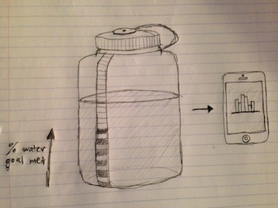
Motivation
For my project, I want to create a smart waterbottle. The most critical part of this project is measuring the water level of the bottle at any given time, such that I can detect how much has just been drunk, filled up, etc.
Design
There are many ways to measure water level; however, most of them are expensive (such as using lasers) or intrusive (such as using magents). For the project, I want to have all the working components on the bottom of the bottle, so I can't have a straw or anything that runs along the length of the bottle.
As such, I need to create a cheap load cell. I used the load step response board to measure capacitance.

Making Board
I used the Modela to mill the circuit board. The machine unexpectedly stopped in the middle of the job, and didn't resume even after I toggled in and out of "view" mode. I simply restared the Modela and it milled the job correctly the 2nd time.
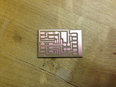
Making Board Cont'd
Finished board.
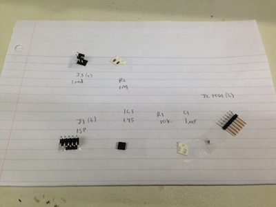
Soldering Board
Preparing to solder the components onto the board. I noticed the lab was out of Attiny44s, which I anticipate needing in the very near future.
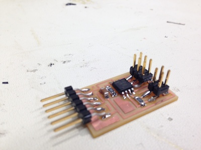
Soldering Board Cont'd
Soldering went pretty nicely. It's kinda like riding a bike. Here's the finished board.
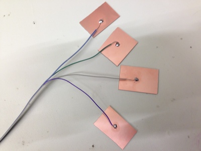
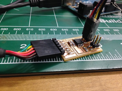
Step Response
I was thinking of ways to test if the board was working, and got inspiration from a fellow student. I soldered wires onto boards that connected to the circuit board.
Embedded Programming
This is where things started to get difficult. I tried programming the board using my FabISP, but the ISP somehow stopped working. Additionally, all the AVRs in the lab were broken. I asked Vivek how he'd been programming and he talked about using an Arduino.
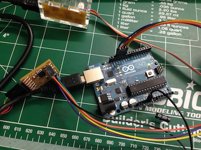
Embedded Programming Cont'd
Vivek walked me through using his Arduino to program my board. You have to connect the Arduino to your computer, and set it as "Arduino as ISP". There are a number of additional hacks needed to make this work, such as putting a ~10uF capacitor between GND and RESET on the arduino, and connecting only the Arduino's GND to your board (not VCC).
After a few hours, I was eventually able to modify the hello.load.45.c code and upload it unto my board.
Testing
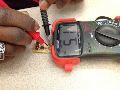
To make sure I was on the right track, I tested to see of the board was behaving properly. Here is the voltage between VCC and GND.
Testing Cont'd
The next step was to somehow read the input into the board. After a few hours of trying other methods, I decided to try hello.load.45.py. This turned out to also be a minor struggle. I already had Python and Arduino on my computer at this point. I opened terminal and tried >python hello.load.45.py and got an error regarding a module named "serial". So I downloaded pyserial, and got the same error until I put the hello.load.45.py file into one the several nested folders in pyserial... I then ran it again, and got an erorr regarding serial ports. So I looked in Arduino to see what port my board was connected to: /dev/tty.usbserial-FTF6COW0. Surprisngly, that worked. The full command I used was >python hello.load.45.py /dev/tty.usbserial-FTF6COW0.
The video shows the results. I'm getting some data now, even though I still have to figure out how to use it.