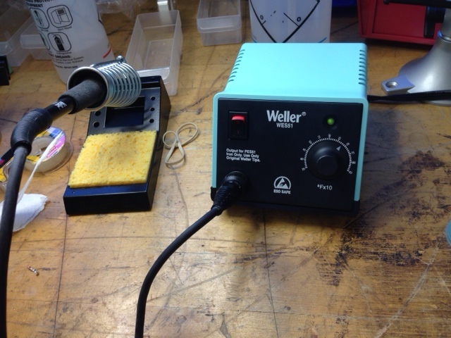
It was my first time ever to use the soldering machine so it was an interesting experience. The last time I had dealt with circuit boards of any sorts was in middle school when we played with circuits, so this was a very interesting experience for me. The solder works very well. The tips I had was to always heat the board and not the actual metal you are melting. The conduction of heat from the board will then melt the metal and then allow you to neatly join the parts onto the board.
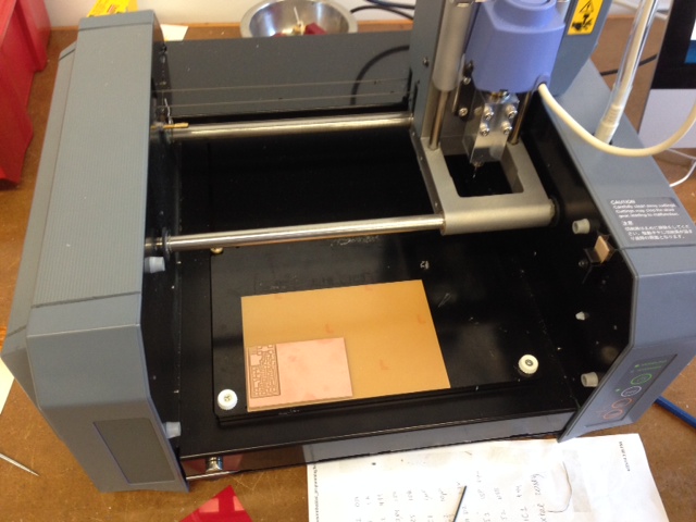
The machine was very interesting to use. We had a ready made template which we chose from online, and which we could readily input into the system. Next, we proceeded to cut the designs using the machine. Neil told us that we will learn more about the logic behind the designs in latter weeks, so we should now focus on cutting out the design and soldering the various diodes and parts onto the board.
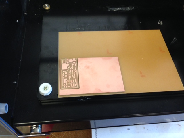
There we are! The design is cut and complete. We also had to cut a border around the circuit board.
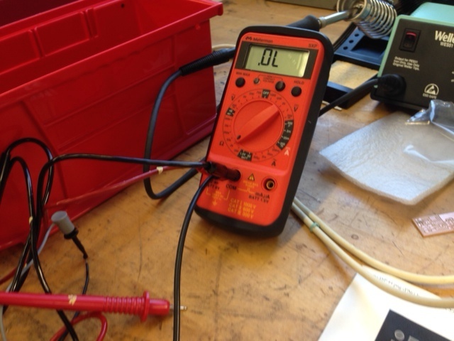
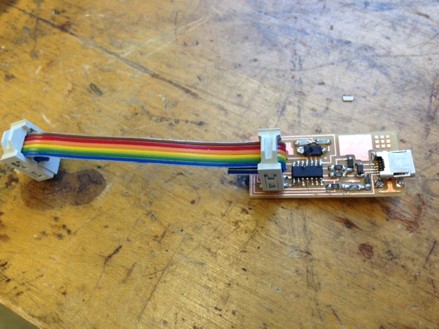
Robert Hart taught me a very good skill which was to use the voltmeter to test both ends of the circuit to see whether or not the circuit was working. This was a very useful skill to know as sometimes it is easy to solder the wrong parts or perhaps have too much solder on some parts of the circuit board, resulting in the circuit board malfunctioning.
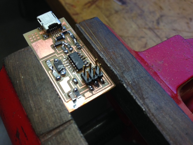
Here is the complete processor circuit board with the diodes, resistors, and other parts soldered onto it. A few tips (1) Print out a design plan on paper and then put the relevant parts accordingly on each of the name. (2) Solder each of the parts on slowly one by one. (3) If there is too much solder on any one path, use some bronze threads to mesh and clean out the extra solder. Initially, I thought that extra solder may be good for the circuit, but I was wrong. Having just the right amount of solder was better, and actually critical to the circuit actually working well!