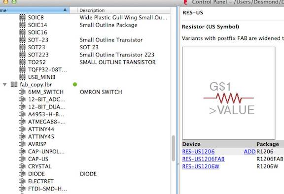
It has been a long while since I worked on physics and circuit board so I was really worried when I first started. I was hesitant on how I was going to be able to complete the project but Rob, Dan, and a couple of others really patiently brought me through this. The essence of this is that things can always be learned, you just got to be determined! The first step we did was to download the fab.copy file which Rob had provided for us into the library. After that, we extracted the final plan on the class tutorial website which Rob had created, and then started to work on eagle to download the parts to make it look like the circuit plan that we were given.
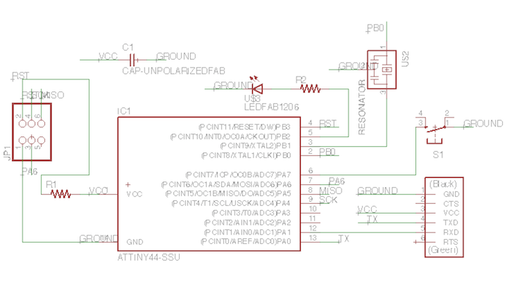
This is the image of the electronics design on the "schematic whereby we were supposed to drag and drop the relevant capacitors, diodes, resistors, and so forth onto the map. It was challenging initially, but as Neil and Rob helped to name most of the items to be dropped off with "fab", it was relatively easy to identify them. The part that was a bit tricky was trying to join the various circuits that were relevant. The trick was to create a "net", "name", and then "label" two circuits that were supposed to be together, but were not next to each other or too far away. For circuits that are near, you can easily create a wire to join them together.
This is the completed circuite design. But there's a couple of advice which I will quote from Rob's email as per below.
1. Find someone who has gotten started and watch and ask them questions.
2. Rather than connect parts with tangles of wires on the schematic, learn to make nets: 'net' , 'label' , 'name'. This connects things with less confusion.
3. I like to use the command line. Type the name of the command.
4. Some useful commands when on the schematic:
net
label
name
junction
ERD electrical design rule
5. Some useful things when working on the board:
display (eg: 'display none top')
show [net name]
rats (ratsnest - clears up the unrouted connections.
info (lets you change parameters).
layer - changes layer on which you are working.
6. To make the interior of the board, draw a rectangle on an unused layer.
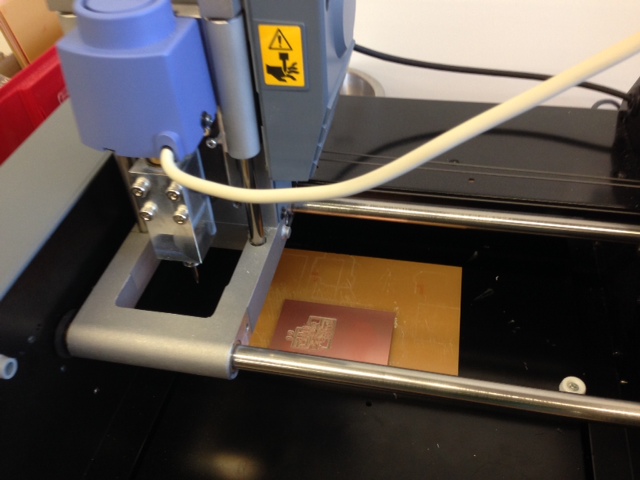
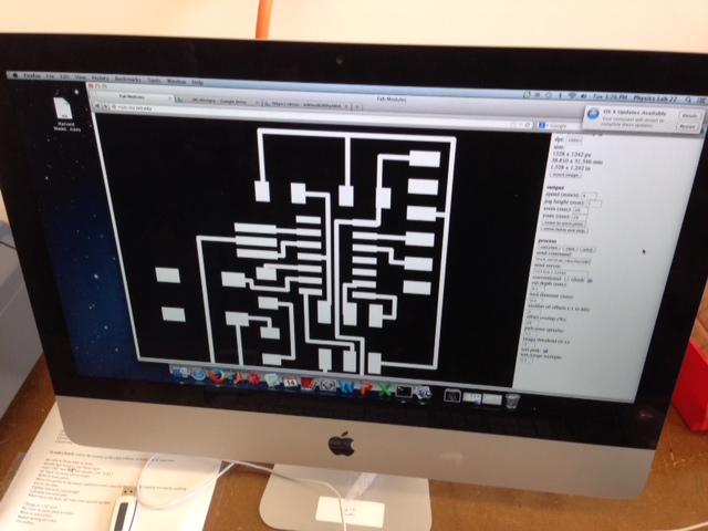
Back to the milling on the modular, which was pretty interesting and challenging too. I needed to firstly change the drills, and to also zero the relevant parts. I had forgotten some of the parts so that was a bit challenging but I managed to relearn them so that was cool. I also stuck my board with insufficient tape, and when I was trying to vacuum the machine, my board got stuck in the vacuum! Lucky I was able to retrive it :)
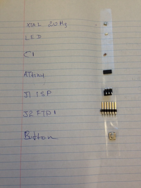
Good advice to lay out the parts you need to solder on before doing so!
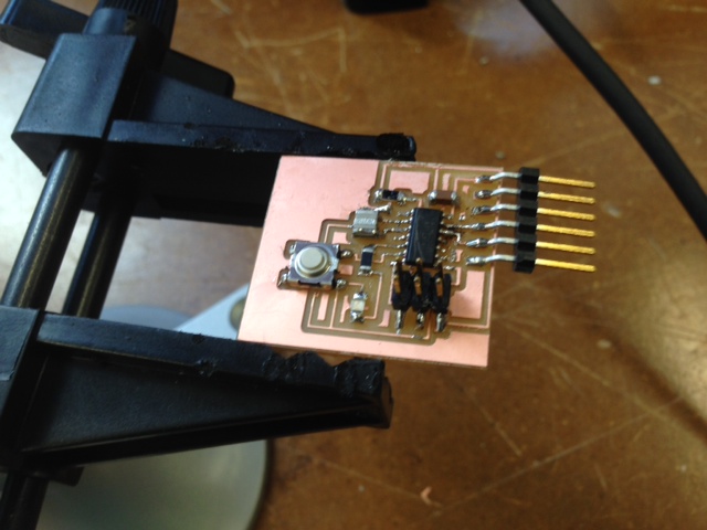
I am getting better at soldering, so after an hour of work here it goes!!
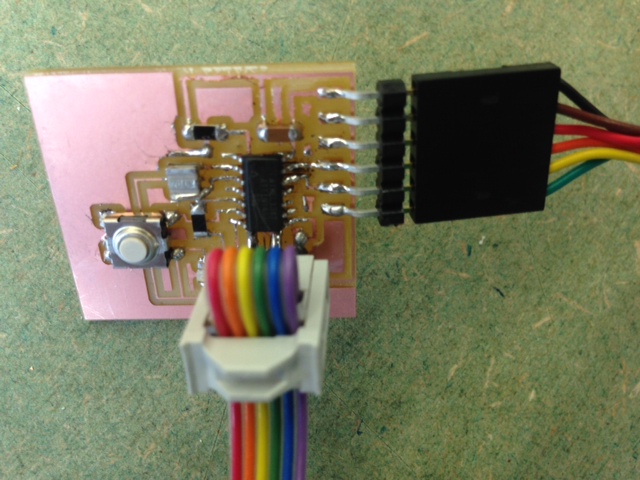
Here is the completed circuit board, which I feel very proud of as I have no experience in this at all!
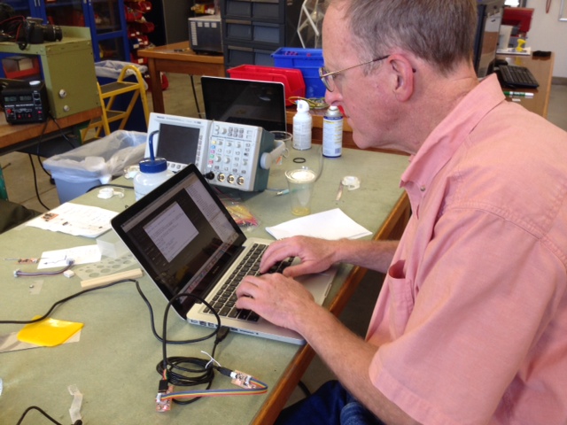
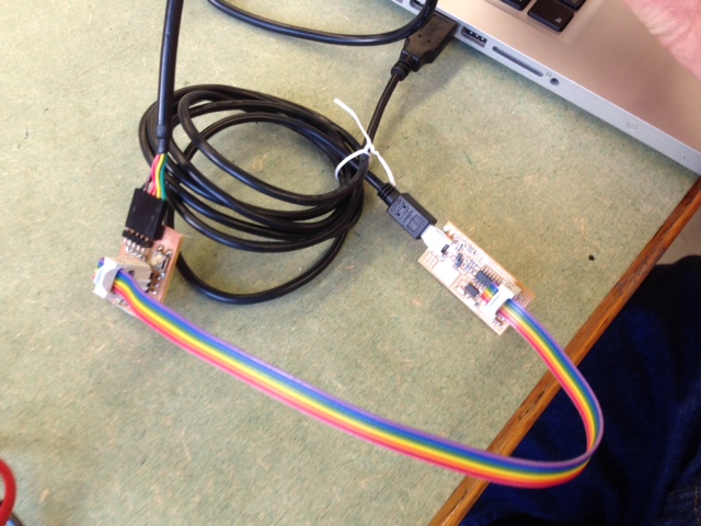
Here is Rob helping to program it. I was pleasantly surprised to find that the program uses C code, which I am now learning in a class called CS 50 at Harvard College.
Unfortunately, my circuit board did not light up the LED light, but I will surely get it to light up next time!
This is the image of the electronics design on the "schematic whereby we were supposed to drag and drop the relevant capacitors, diodes, resistors, and so forth onto the map. It was challenging initially, but as Neil and Rob helped to name most of the items to be dropped off with "fab", it was relatively easy to identify them. The part that was a bit tricky was trying to join the various circuits that were relevant. The trick was to create a "net", "name", and then "label" two circuits that were supposed to be together, but were not next to each other or too far away. For circuits that are near, you can easily create a wire to join them together.
This is the completed circuite design. But there's a couple of advice which I will quote from Rob's email as per below.
1. Find someone who has gotten started and watch and ask them questions.
2. Rather than connect parts with tangles of wires on the schematic, learn to make nets: 'net' , 'label' , 'name'. This connects things with less confusion.
3. I like to use the command line. Type the name of the command.
4. Some useful commands when on the schematic:
net
label
name
junction
ERD electrical design rule
5. Some useful things when working on the board:
display (eg: 'display none top')
show [net name]
rats (ratsnest - clears up the unrouted connections.
info (lets you change parameters).
layer - changes layer on which you are working.
6. To make the interior of the board, draw a rectangle on an unused layer.
Back to the milling on the modular, which was pretty interesting and challenging too. I needed to firstly change the drills, and to also zero the relevant parts. I had forgotten some of the parts so that was a bit challenging but I managed to relearn them so that was cool. I also stuck my board with insufficient tape, and when I was trying to vacuum the machine, my board got stuck in the vacuum! Lucky I was able to retrive it :)
Good advice to lay out the parts you need to solder on before doing so!
I am getting better at soldering, so after an hour of work here it goes!!
Here is the completed circuit board, which I feel very proud of as I have no experience in this at all!
Here is Rob helping to program it. I was pleasantly surprised to find that the program uses C code, which I am now learning in a class called CS 50 at Harvard College.
Unfortunately, my circuit board did not light up the LED light, but I will surely get it to light up next time!
Here is Rob helping to program it. I was pleasantly surprised to find that the program uses C code, which I am now learning in a class called CS 50 at Harvard College.
Unfortunately, my circuit board did not light up the LED light, but I will surely get it to light up next time!