This week we were supposed to work on input devices. I was initially really afraid of this week as my week 6, embedded programming did not go well. Nonetheless, I decided to set my heart to it, and re-learnt the ropes step by step, starting from Eagle. I decided to work on a photo transmitter as I was interested in the area, and started to follow Neil's online guide to work on this step by step.
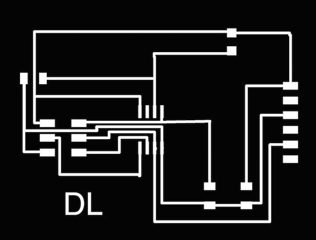
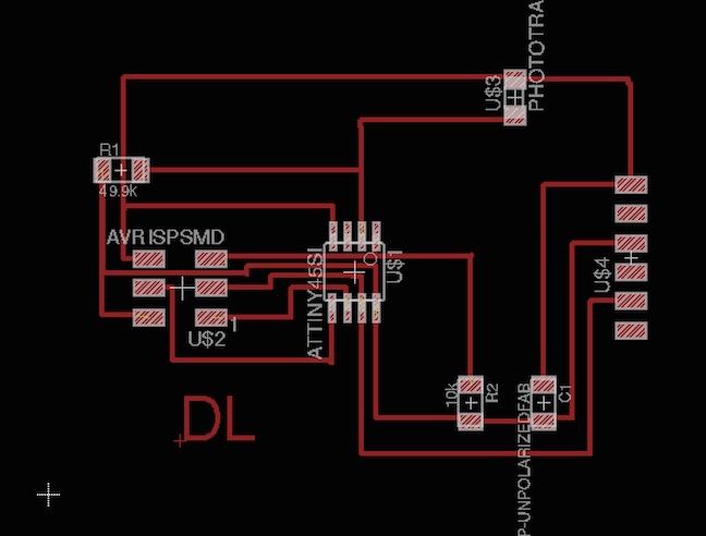
My Eagle design actually turned out pretty well! I learned to test all the circuits properly using "Show GND", or "Show VCC" to ensure that the proper circuits are being linked. I used the following steps in my design of eagle which is (1) Open a new project (2) Open a new schematic (3) Type add (4) Go to Fab.copy (5) Start to drag and drop resistors, capacitors (based on Neil's outline) (6) To connect them use nets (7) label (8) name to connect (9) or simply use "wire" to connect them. (10) Once all wires are connected, change to schematic (11) Use rats, route, ripup to make the design look better (12) Use display to show only the top layer (13) Select monochrome (14) 1,000 dpi (15) Export as PNG (15) For the outline, select only dimension, and add a rectangle (16) Similarly export as PNG, monochrome, 1,000 dpi
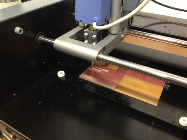
In the milling process, I realized that I needed to zero different parts of the board as it was uneven. I worked with the TA to try and zero different parts of the board, and used cut depth 0.011 instead of 0.01 mm, that worked great. I also made sure to push down the drill firmly touching the board while I was zeroing it.
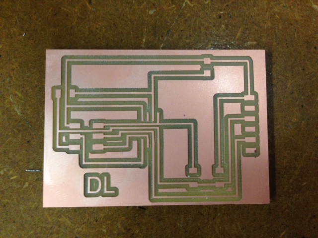
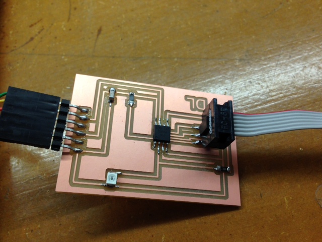
The board turned out really nicely, and all the cuts were great. I was very pleased with this.
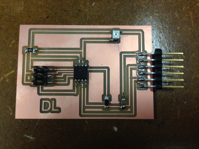
I started to solder on the parts onto the board. I first laid out a plan, and then selected all the parts. I had some problems with choosing the 49.9K diode, and found that it was all on the labels in the end. I also had some problems with orientation, and learned that the best way is to read the data sheet, though tiring, but that will solve many problems later on. I also learned that it is critical to get all these steps correct right from the start!
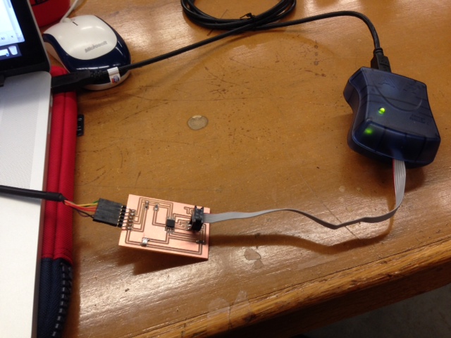
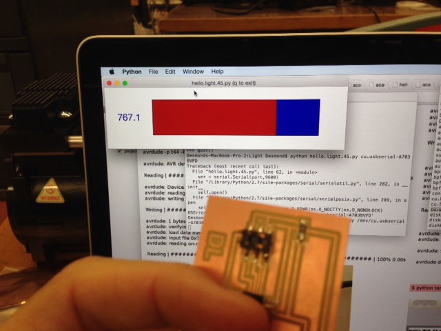
Next I am going to try and program it! I was really happy as when I connected the AVRISP2, the light turned green! It was the first time ever that my board worked smoothly, and I was very happy to. To program it, I mainly followed this link: http://academy.cba.mit.edu/classes/embedded_programming/hello.ftdi.44.program.png, which was very effective. I sat by the TA, and we went through the programming part together. The steps I did were (1) Create a folder on desktop (2) Download the hello.light.45.c and makefile into the folder (3) Next, I used cd ~/Desktop/Folder to navigate into the folder (4) Typed in "avrdude" in terminal (5) make -f hello.light.45.make (6) make -f hello.light.45.make program-avrisp to program the AVRISP (the blue thing) (7) At this stage, the PCB board should be programmed. (8) Next, I need to ensure that I have python in my program. (9) I need to find the location of the port which the FTDI cable was connected to on my laptop. To do that, the TA typed in cd ~/dev on my terminal window to find the USB port that was connected and that name associated with it. Next, I typed in python hello.light.45.py cu.usbserial-A703BVFD to program the PCB board.
Programming using the FTDI cable
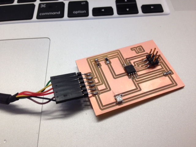
Another nice picture
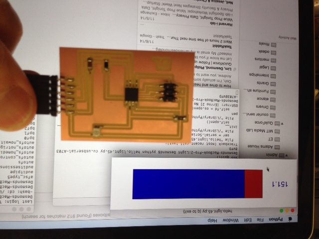
Now there is light...