This week we are working on output devices, to program our processor circuit boards ("PCB") to either produce audio, video, words (or a LCD screen), or a DC motor. I wanted to program mine to use a DC motor, as I am contemplating working on a scooter or bicycle for my final project. This is PCB that I came up with. I am getting better at coming up with the PCB quickly, and hope to be able do this design quickly compared to in the past moving forward. One amendment to the Eagle design, use "Net, label, name" to join the wires, and use "Top display layer" for the traces, and "Bottom display layer" for the outline. Add a rectangle afterwards (the black box) to add the outline.
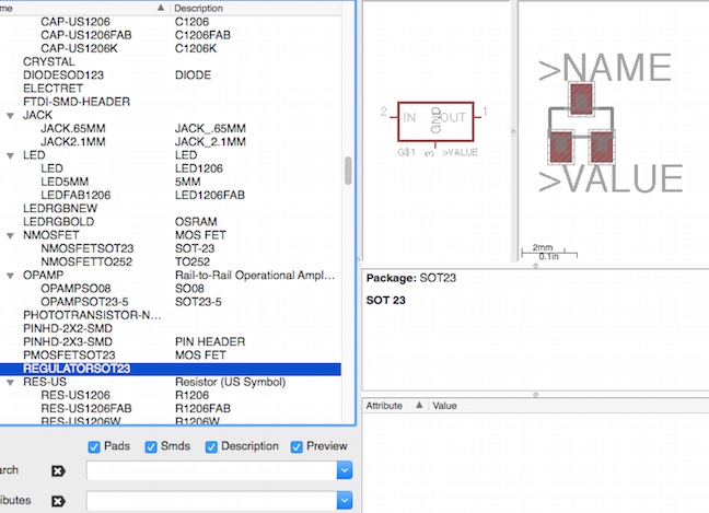
I had problems locating the regulator ("IC2 5V") on the parts as part of "fab.copy" in the projects. This is the screenshot of what I finally used in fab copy. They have different names, but this is the one.
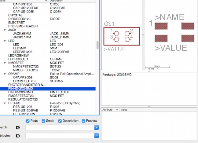
I also have problems trying to locate the J2 and J3 motor. In the end, I was able to locate it as per this screen shot here.
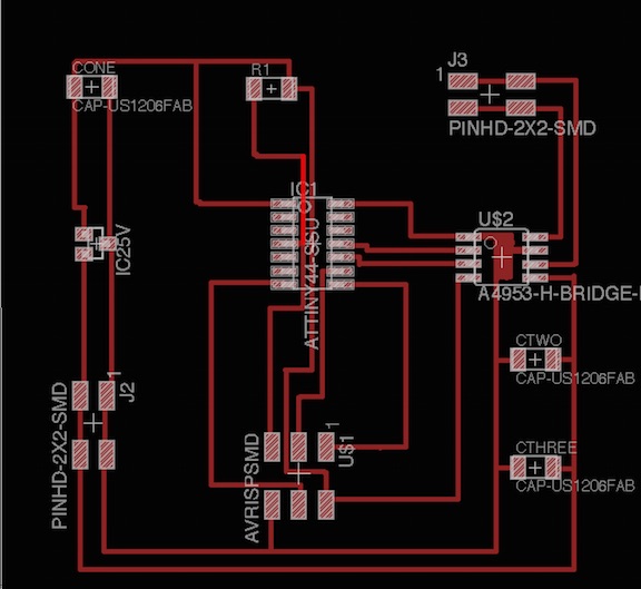
This is the final design that I used for my PCB board design. The problem with this was a per follows (1) Board is too big, too much space and wasteful (2) Some of the traces were too close, resulting in the miller not cutting it properly (3) I need to design this better to allow for better milling.
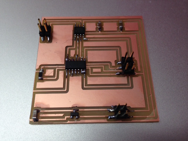
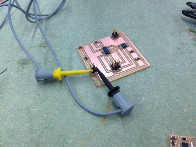
I was able to mill the board and solder all the parts on, but there were couple of problems that came up that prevented me from testing and programming the board. The problems were as follows (1) Traces were too close such that they were connected in the wrong way that they should not be (2) The traces were too thin and not connected enough (3) Dirty board with copper and solder traces. The solutions are as follows (1) Do better planning and design to allow for enough space (2) Use a wire to connect (3) Use a knife or ruler to hack and clear some of the wrongly connected paths (4) Wash and clean off the copper and solder traces with soap and water, then blow dry it.
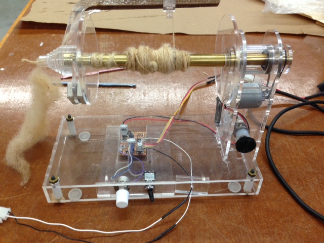
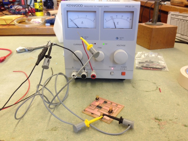
Another picture where we connect the power supply to my PCB using the two connectors to "GND" and "VCC".
This is the motor we use to test the voltmeter
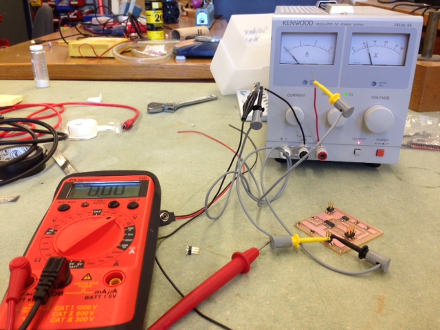
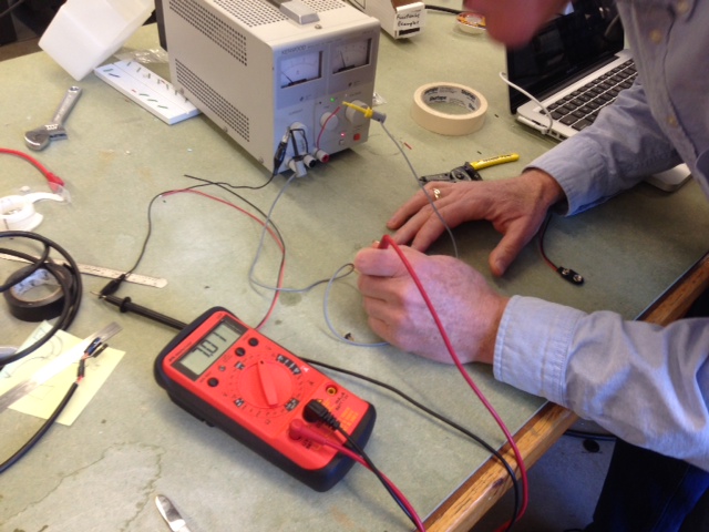
Another picture of testing the processor circuit board
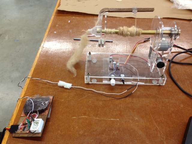
An interesting project by Robert Hart of how to use the DC motor.