Week 11: Networking and Communications
This week, I worked with Alexis Hope and Bianca Datta to make a series of Fabduino devices that talk to each other.
The plan was to make six Fabduinos, then use the nRF24L01+ (2.4 GHz ISM) chips to have three pairs of Arduinos talk with each other.
The nRF24L01+ Modules

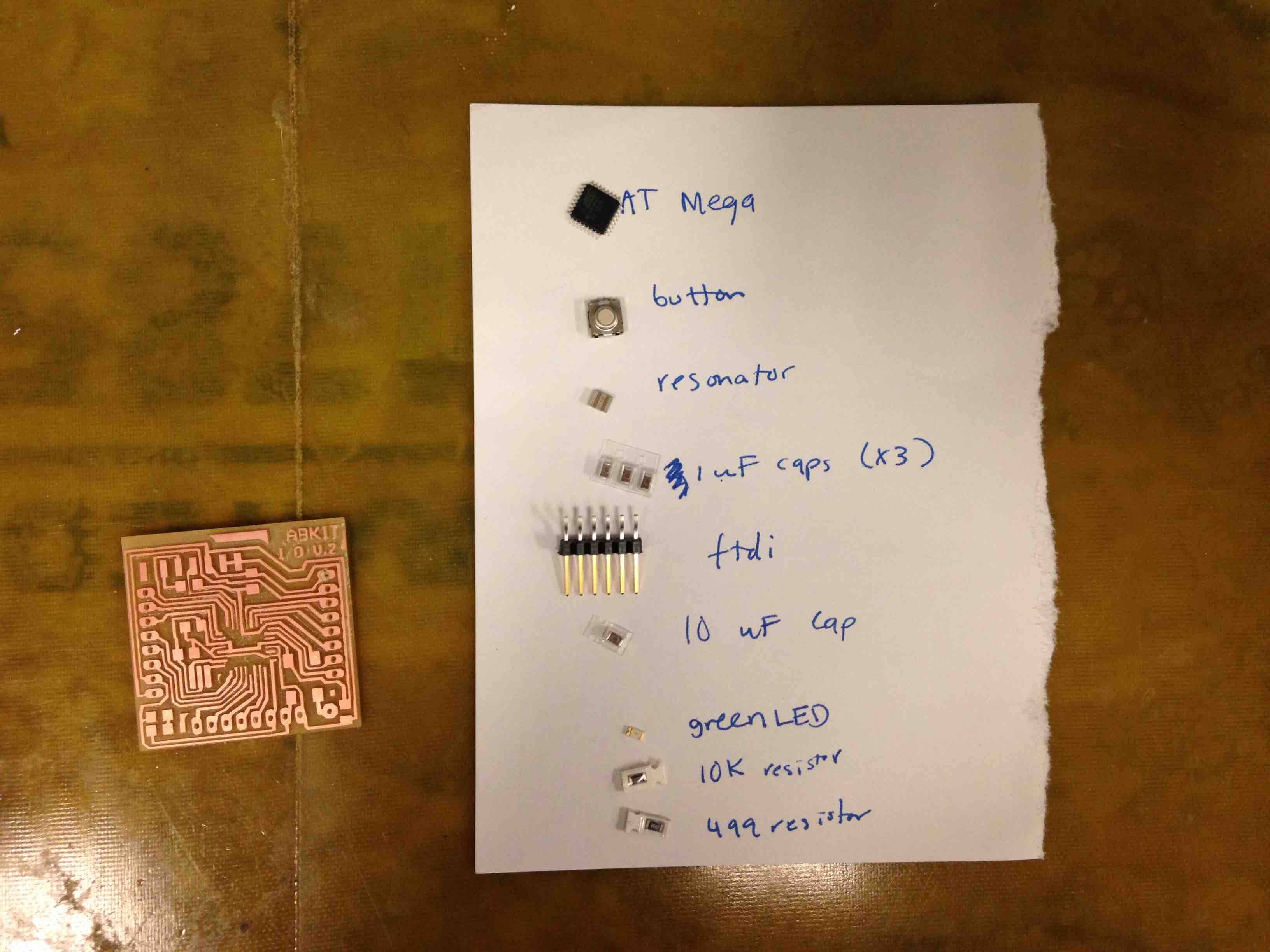
We began by fabricating the Fabduinos. We milled the traces with the Modelas, which took many more hourse than we anticipated. One of the Modelas broke on Sunday, which meant that we had a huge backup of people that needed to use one machine. As such, we decided to mill three Fabduino boards, and then work together to make two talk to eachother.
One observation we had while milling the Fabduinos was that when trying to mill the through-holes for female adapters, we found that inverting the image was helpful. THis made the hole smaller, which fit within the constraints of the PCB.
Once we milled the Fabduinos, we then stuffed them. I use a bunch of flux to make soldering the pads of the chip.
Stuffing the Chips

We then followed the instructions on the Fabduino page for how to burn the bootloader using the Arduino interface. And sucessfully programmed the onboard LED to blink!!
Finished Fabduino

[The nRF24L01+ breakout board is next to it for size]
Next, we hooked up the nRF24L01+ breakout boards to two of the Fabduinos. Since the Fabduino is powered with a 5V FTDI cable (and the 3.3V FTDI does not have run at 3.3V for VCC), we used a 3.3V regulator to regulate the VCC going into the breakout boards.
Setting Up the Breakout Boards

We then downloaded example code from the RF24 Github repo and compiled and ran the “Getting Started” code. After many attemps, we could not get it to work. We tried the “Ping and Pong” code as well, but that also failed. We think that the chips may have been effected by the 5V power we gave them before relizing that we should power them with 3.3V.
Troubleshooting
