Week 3: 3D Printing
This week, we learned about 3D printing. The requirement for the project was to design and print something that could not be made easily without 3D printing. I decided to make a Rubiks Cube, since it has a bunch of interlocking parts and could theoretically be printed fully assembled.
I started by understanding how a Rubiks Cube works and CAD-ing my own in Solidworks. Below are snapshots of the four components of the cube: the corner pieces, the edge pieces, the center pieces, and the yoke.
Parts of the Rubiks Cube
Yoke - This is the component in the inside of the cube that holds the four sides together

Center Piece - These attach to the yoke
Edge Piece - These interlock with the center pieces

Corner Piece - These interlock with the edge pieces
Next, I created an assembly in SolidWorks, using a 0.015 inch gap between the parts of the cube so that it could be printed on the Dimension 3D printer, and exported the assembly as a .stl mesh.
Full Assembly in SolidWorks

Cube Cross-Section in SolidWorks
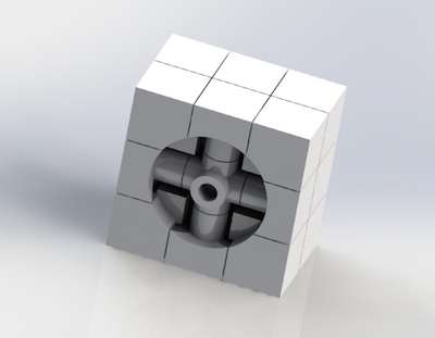
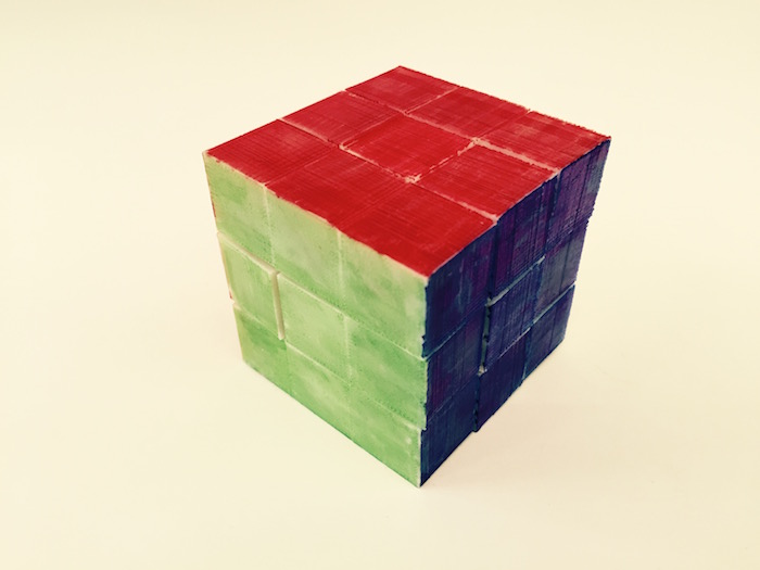
Tom printed the cube and then put it in a bash to dissolve the supports. Finally, I had a 3D printed cube :)
Final 3D Printed Cube

Cross Section of the Cube

Some things I learned from this week are:
- To build in more spacing that 0.15 inches between the pieces to ensure that they move
- To pay more attention to how the mates I make in SolidWorks export to the mesh. There was an issue with how the center pieces and the yoke mate together, making it impossible to fully rotate the cube.
… In otherwords, its a perfectly solved Rubiks Cube and cannot be unsolved.
I also 3D scanned a LEGO to understand more about how 3D scanning works with the SENSE scanner. I had issues with keeping a steady hand and the correct distance away from the object, but ended up getting a somewhat LEGO-like object.
LEGO Scan
