Knowing that this will turn into a very long post, here's a teaser video of the first test of the wall plotter. Filmed in the Science Center Lab at Harvard. Zach Seibold is driving the plotter with sliders in Grasshopper. There are a number of issues, mostly that the stepper motors are releasing and not holding position, and the carriage / tool head doesn't exist yet.
And here's a video of the more or less finished version the night before the final presentation. The Grasshopper definition being used to control the wall plotter motion can be downloaded here.

A work-in-progress rendering of the robot. This includes 4 wall mounted "feet" and a carriage head that contains the end effector. Wire robots belong to a class of robots called parallel manipulators. My motivation for switching to a wire robot design is well described here.
Parallel Robots tend to have limited workspace, due to limitations of the stroke of linear actuators. Wire robots (or cable robots, or tendon-based Steward platforms) address this by substituting actuators with cables. The flexibility of wires allows large changes in the length of the kinematic chain, for example by coiling the tendons onto a drum. This allows them to overcome the purely geometric workspace limitation factor of classical robots. Wires can be coiled by very fast drums while the moving mass of the robot is extremely low, which allows the robot to reach very high end effector speeds and accelerations.

The above diagram describes the auto-calibration process for the robot:
1. Mount motors and spring components on wall. Allow tool head to hang from the springs, finding a point of semi-equilibrium between the two. Then actuate motors 1 and 2 by some arbitrary small distance so that the system is under tension. Consider this arbitrary location of the tool head the new origin (0,0).
2. Actuate Stepper Motor 1 until the tool head hits a limit switch mounted on the motor casing. Derive length a from the number of steps needed to hit the switch.
3. Return the tool head to the origin position (0,0) and repeat the process with Stepper Motor 2, finding the length of b. Finally, actuate Stepper Motor 1, releasing Stepper Motor 2, to find the length of c.
4. Given the 3 side lengths, the angles between them can be calculated with basic trigonometry. However, there is insufficient information to determine the rotation of triangle abc in the XY plane. This will be resolved by the installation of an accelerometer in the tool head to determine the gravity vector.
Here is a video of the above calibration routine. I did this in C# in Grasshopper; the source code is posted on my Week 13 page. The only thing omitted at this point is the accelerometer data, which I'll add in once I have the accelerometer working correctly.

The above diagram outlines my abmitions for wireless control for my final project. I'd like to wirelessly control three nodes from from a RxTx board attached to the host computer. For this week's assignment I decided to focus on the carriage node, which would need to transmit accelerometer values and receive servo commands. I decided to use the nRF24L01 modules, recently commodified and new to the fab inventory this year.
The above video shows a simulation of the workspace of this type of wire robot. Huge thanks to Greg Phelps for Mathematica help. The use of weights and pulleys (or, substitute for constant force springs) makes for an interesting workspace calculation. In the above simulation (abstracted in unitless values):
(x0, y0) = (-1,-1) (left stepper motor)
(x1, y1) = (1,-1) (right stepper motor)
(x2, y2) = (1,1) (right counterweight)
(x3, y3) = (-1,1) (left counterweight)
force of springs fs = 1
force on stepper 1 = f0
force on stepper 2 = f1
mass*gravity term (alpha) = 0.1
The simulation is plotting the region which satisfies the condition that each stepper can only put out positive force (i.e. pull on the string) and that force must be less than some value fmax, which is changing here.
(x1, y1) = (1,-1) (right stepper motor)
(x2, y2) = (1,1) (right counterweight)
(x3, y3) = (-1,1) (left counterweight)
force of springs fs = 1
force on stepper 1 = f0
force on stepper 2 = f1
mass*gravity term (alpha) = 0.1
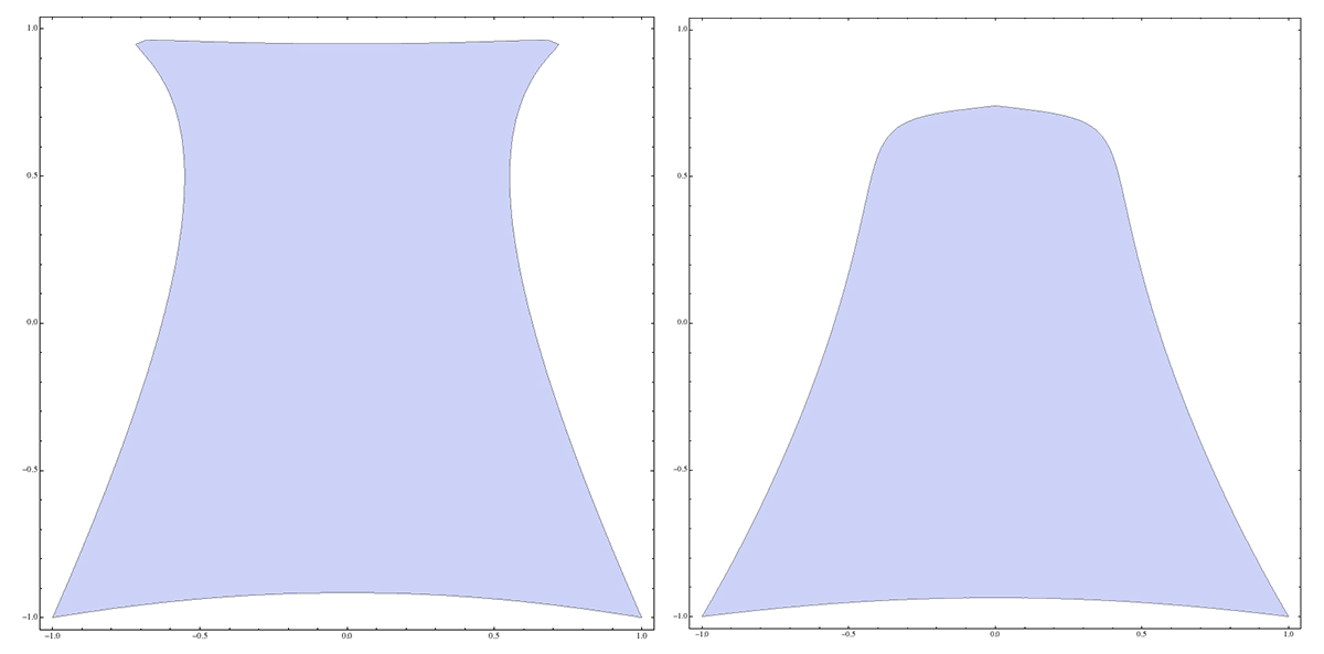
Visualization of workspace approximation, in unitless values, comparing the achievable workspace of a lightweight carriage head vs. one 5 times the mass. All other values remain the same.
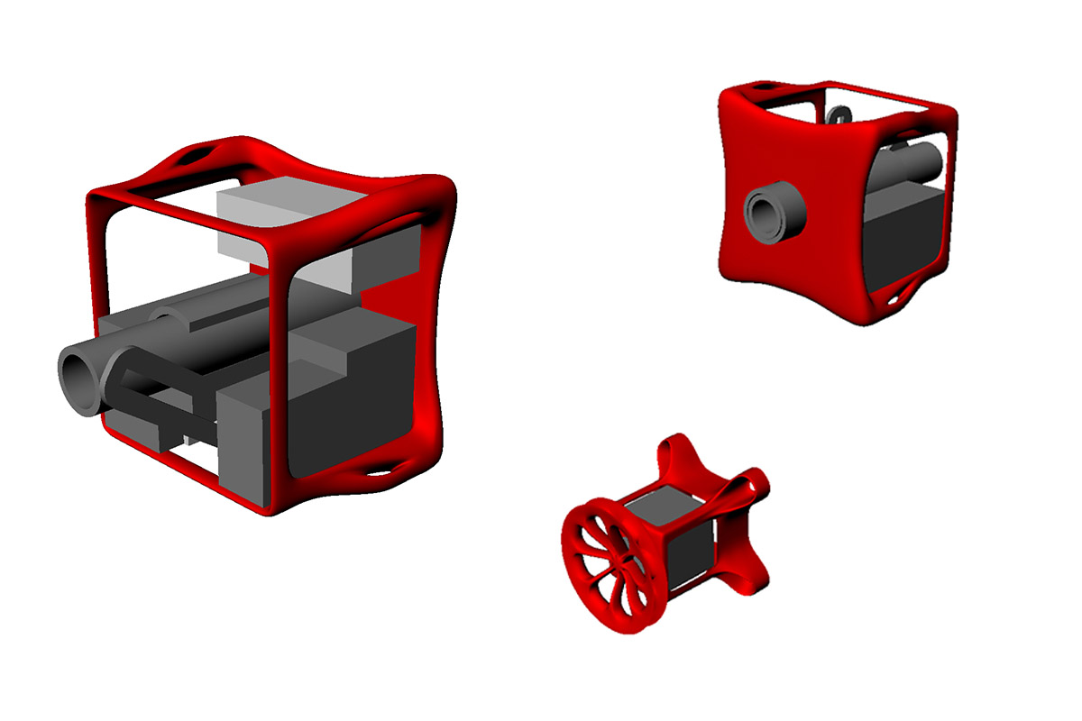
Renderings of the carriage (front and back) and foot of the plotter. It is intended to be a modular changeable tool head system. For now I'm designing it to hold a marker, but it could be configured to hold other tools (spray can, etc.).
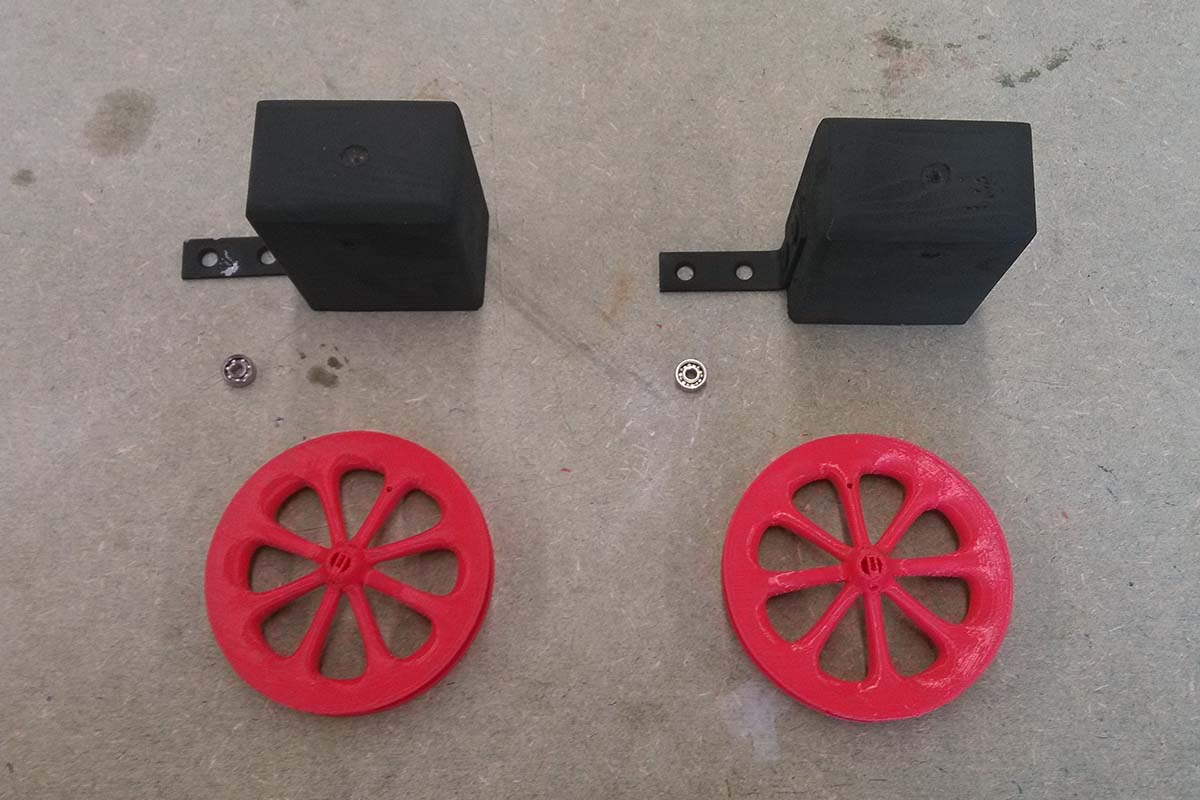
New version (left) and previous version (right) of the foot design. I decided the one on the right required too much plastic for not enough purpose, so I slimmed it down to structural essentials.
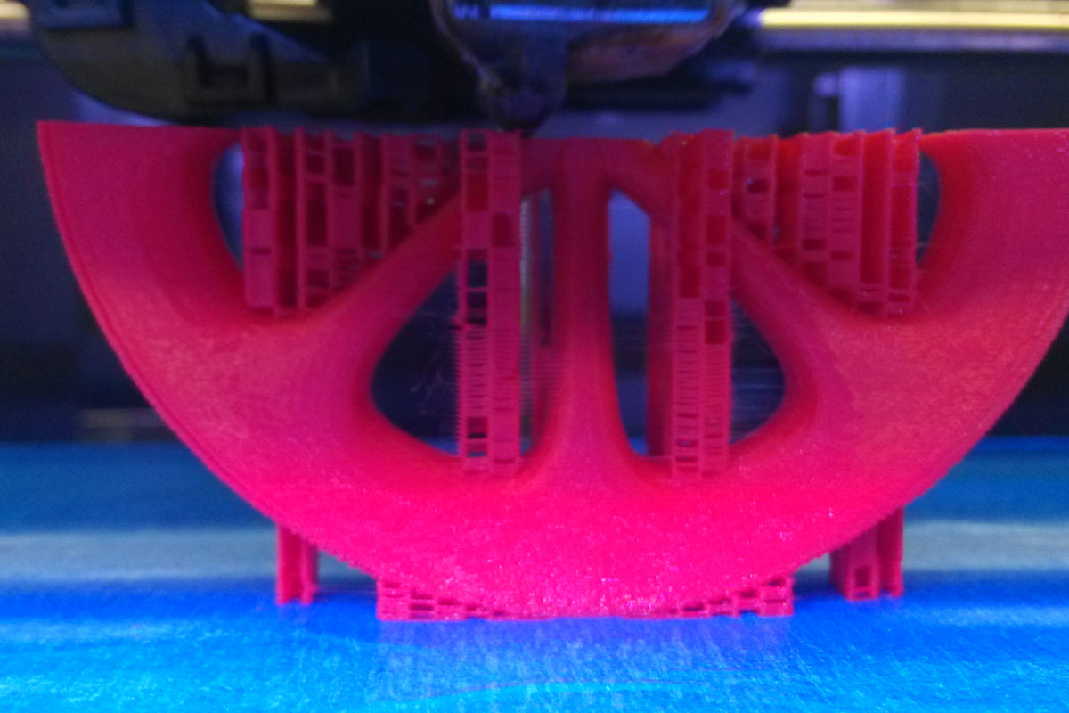
3D printing the wheel. By this point, our 3D printer was really struggling. I was constantly unloading the filament, opening the head, cleaning the gear shaft, cleaning the extruder, putting it all back together, loading the filament, rewiring connections on repeat, just to see print after print fail.
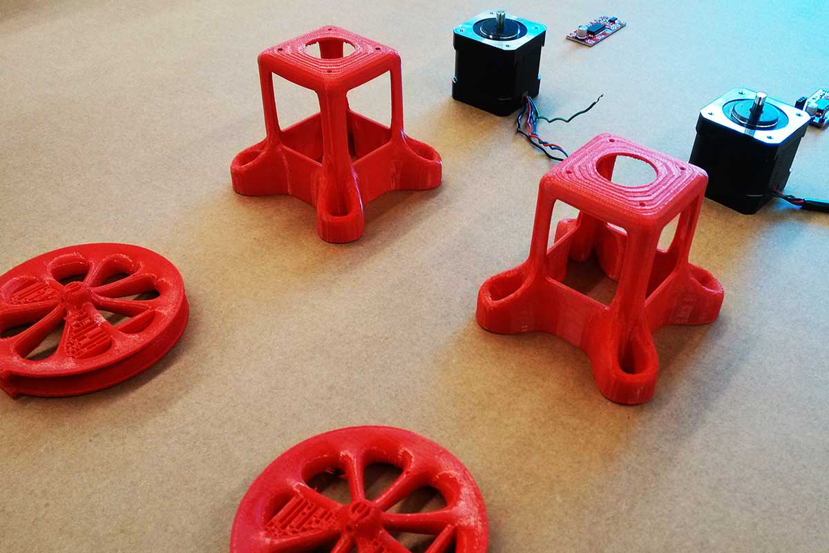
Pieces ready to be assembled. Missing the limit switches.
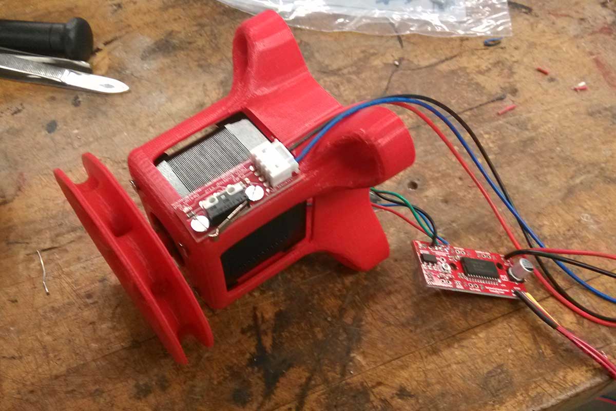
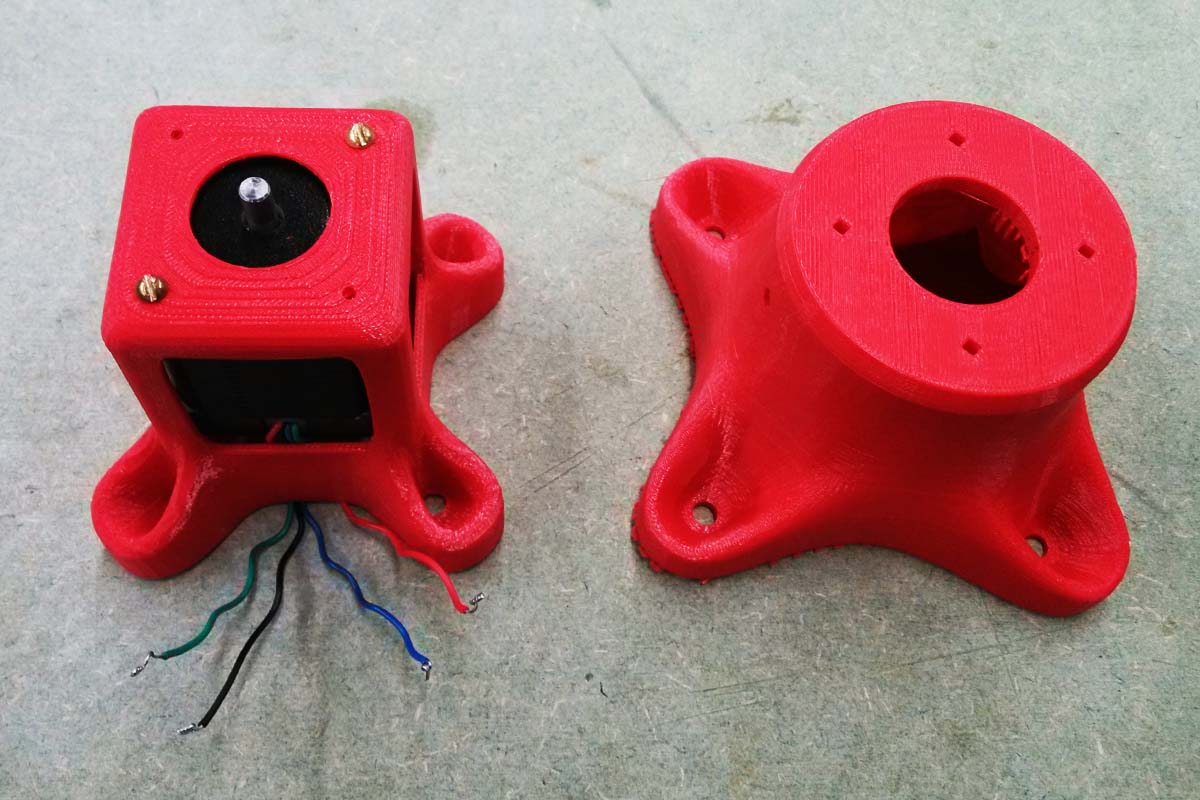
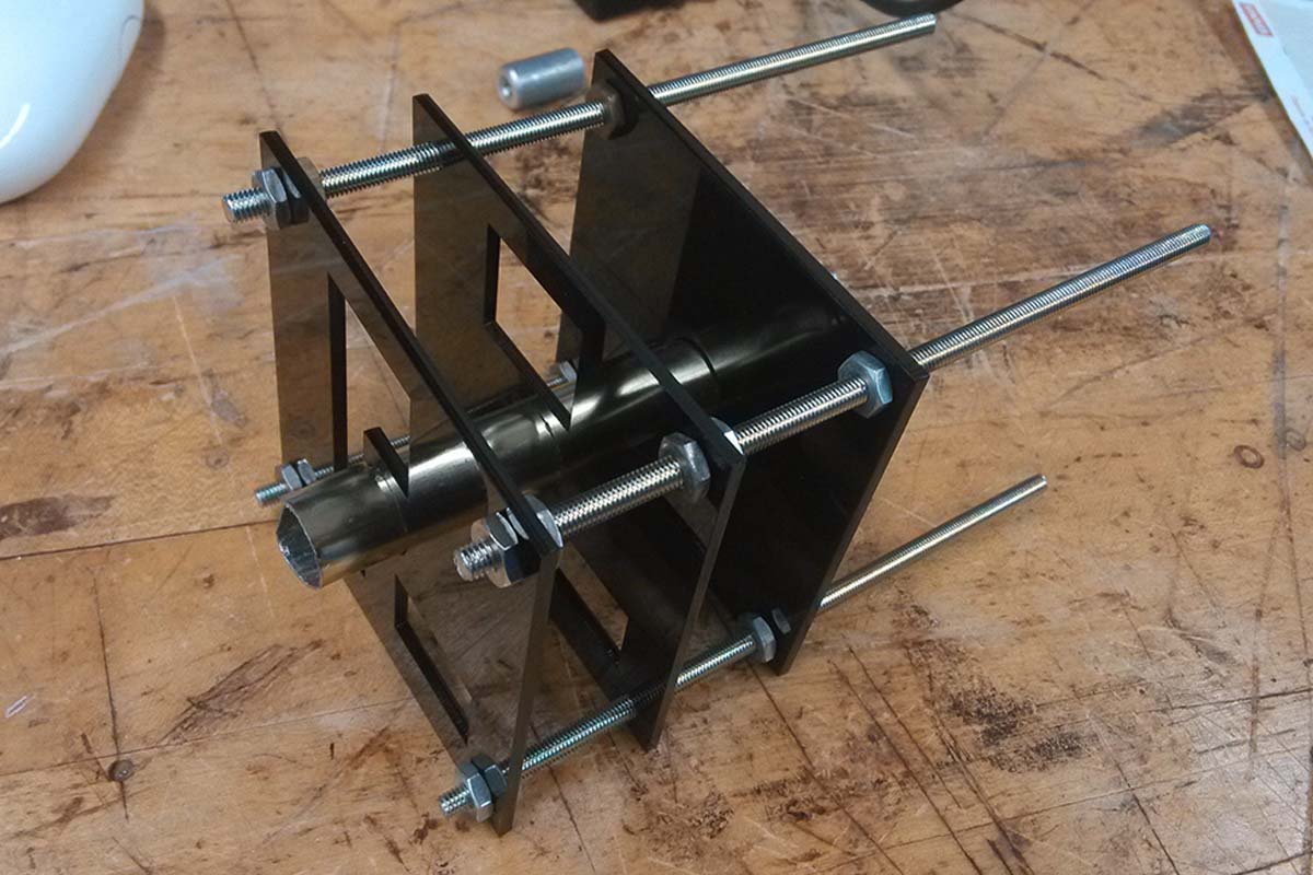
The motor mounts, mostly assembled. The motor drivers will eventually fit into the back of the motor mount, just left out for now while I'm making adjustments. I planned on milling and stuffing my own motor drivers, but haven't gotten around to it yet. Also, these EasyDrivers are inexpensive and more functional than what I would be able to create myself.
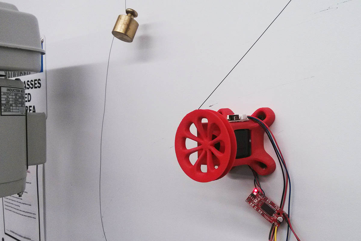
I mounted the first working prototype on the wall of the Science Center lab. I connected the motor drivers to a Fabduino I made, and used Firefly for Grasshopper to command the stepper motors. At this point I spent a good bit of time going through the Arduino sketch for use in conjunction with Firefly, called the "firmata". The problem was that it was uni-directional, constantly streaming commands from Grasshopper to the Fabduino. When I tried to introduce a "read" loop (which ideally would return the state of the limit switches) the interrupt caused the firmata to communicate incorrectly with Grasshopper. I'll try to find a way to make this work later.
I'm still working on designing and printing the carriage head, so for now I decided to use just a fixed marker while I tweak the movements of the stepper motors.
Next I lasercut this prototype, as the 3D printer was still really struggling, and I wasn't sure it would be an option.
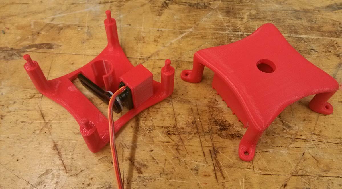
But finally, we got the printer working again. Here are the two pieces of the carriage head. They snap together, so that the end effect can be removed without removing the cables or changing the position of the carriage. The idea is that in the future, I could design other end effectors (slightly larger one for a spray can for example), and they would still work with this system.

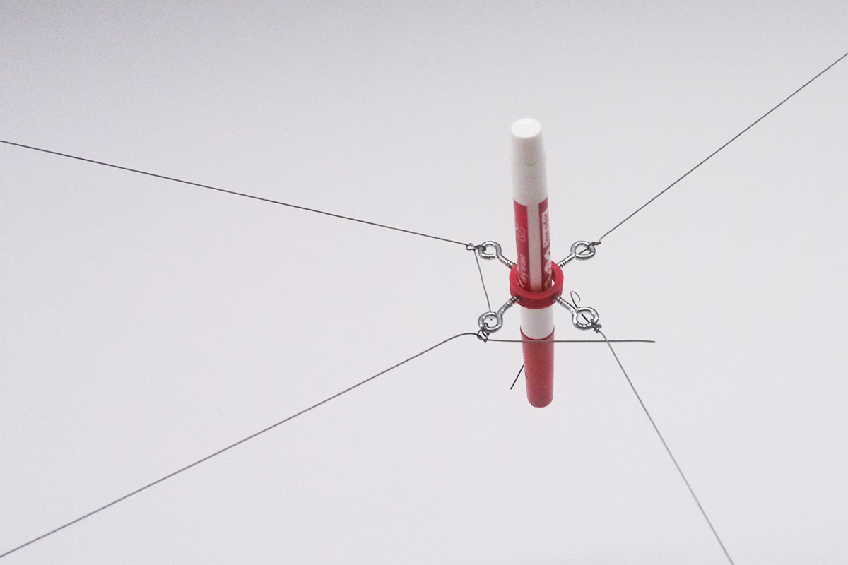
The carriage head assembled with the servo motor to control the Z axis (pushes pen to canvas). The actuator is made from a small piece of laser cut acrylic and a chopped curtain rod to hold the Sharpie, as this minimizes friction. There is room to hold a 9V battery, but for now I'm powering a custom board via USB.
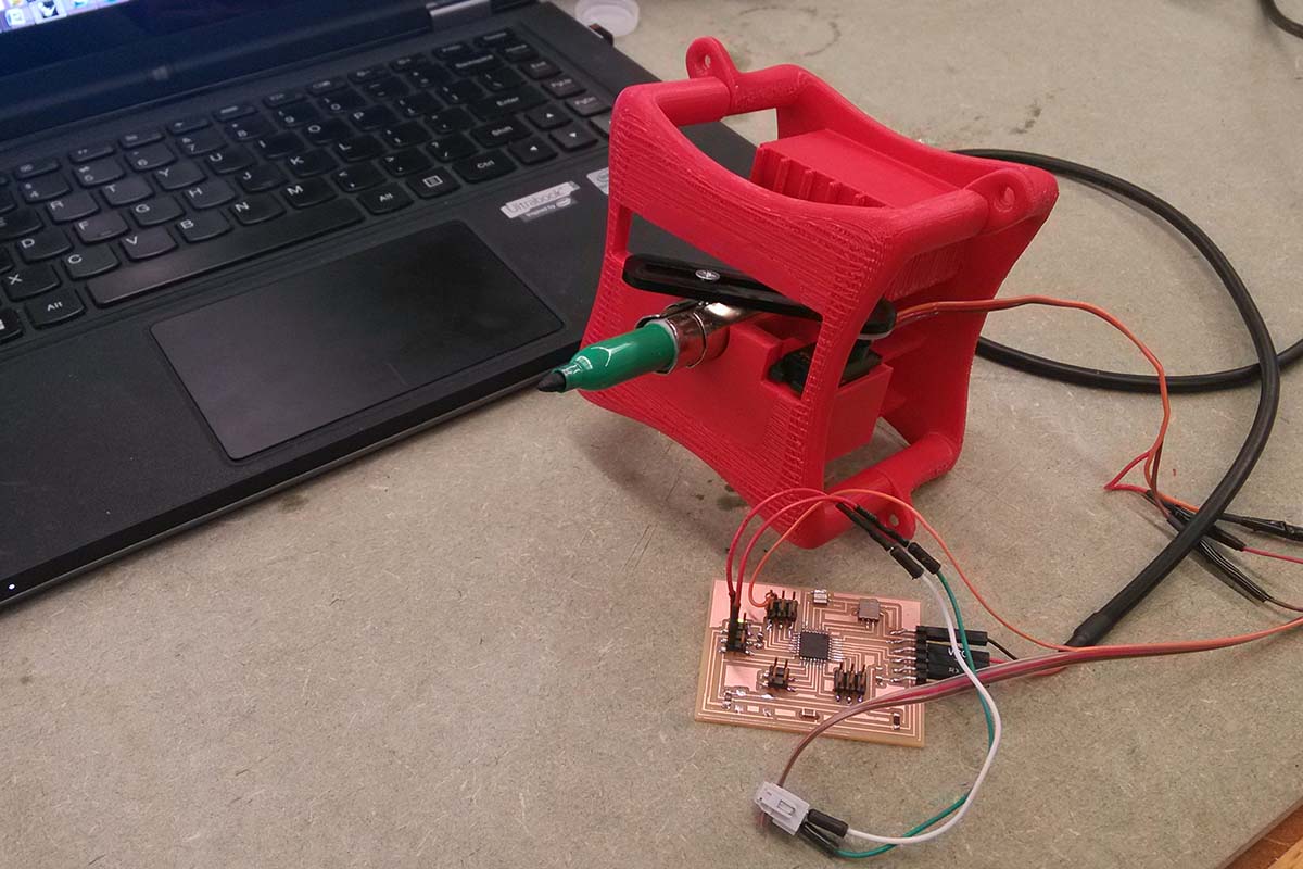
The board I designed for this first iteration of the wall plotter is a Fabduino modified to read an onboard accelerometer, which will be used during the calibration routine. I plan to revise this design to include a voltage regulator so that it can be 9v battery powered. Additionally, I'd like to have pen-up commands communicated wirelessly, so the next version of this board should be able to hold an nRF24L01 module.
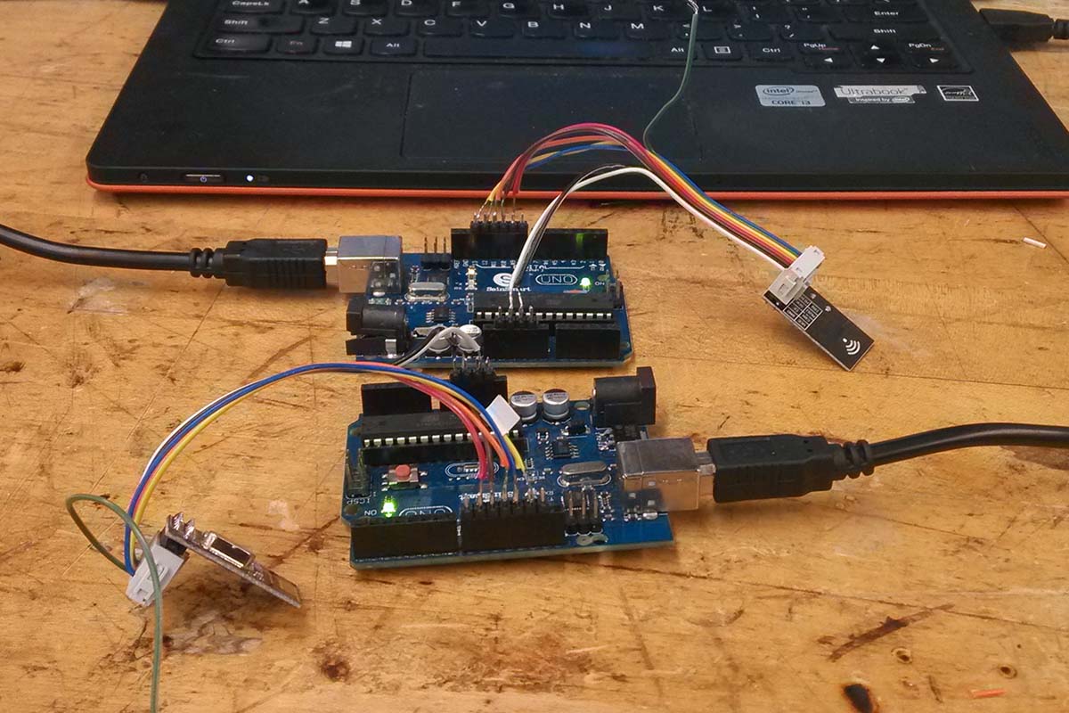
Tout and I revisited these wireless transceiver modules, which I had been unable to get working correctly during networking week. We still really struggled with them, and I decided to table this feature until I had more of the plotter working (with wires).

The wireless modules still aren't working correctly, but here is a gif of the carriage head. It's reacting to a toggle I've made in the Grasshopper definition, which alternates between two fixed angles. It seems to be fast enough to work. These toggles will later be modified so that the pen goes down before starting a new line and up after completing it.
I decided to take the plotter off of the wall and mount it to a piece of plywood so that I'd be able to transport it to MIT for the presentation. But first I needed to make pulleys for the top corners. I used spare bearings and made two wooden feet so that the pulleys would be planar with the coils on the bottom.
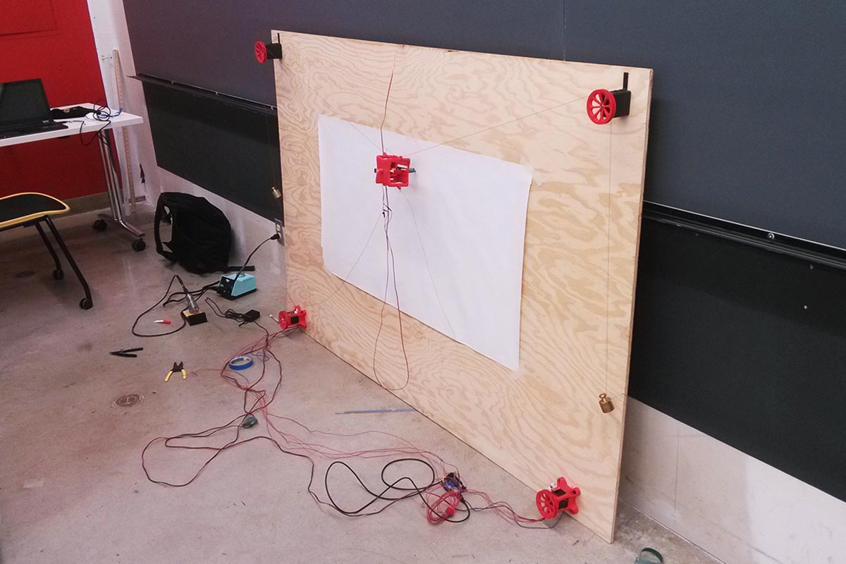
Putting the final touches on the plotter before taking it to MIT. There was a lot that I didn't get around to doing, but at least I have a working project!

I noticed the plastic was getting super hot, so as a final touch I glued in pieces of aluminum to act as heat sinks.
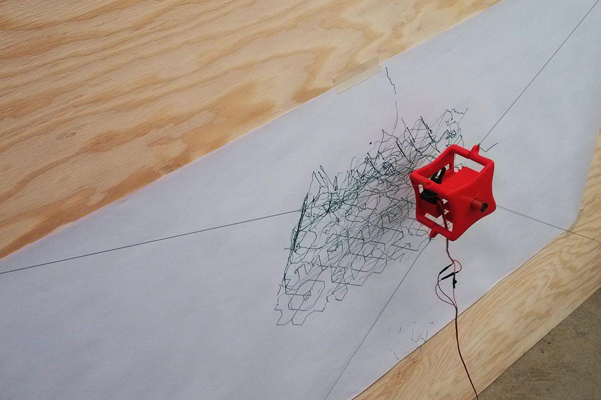
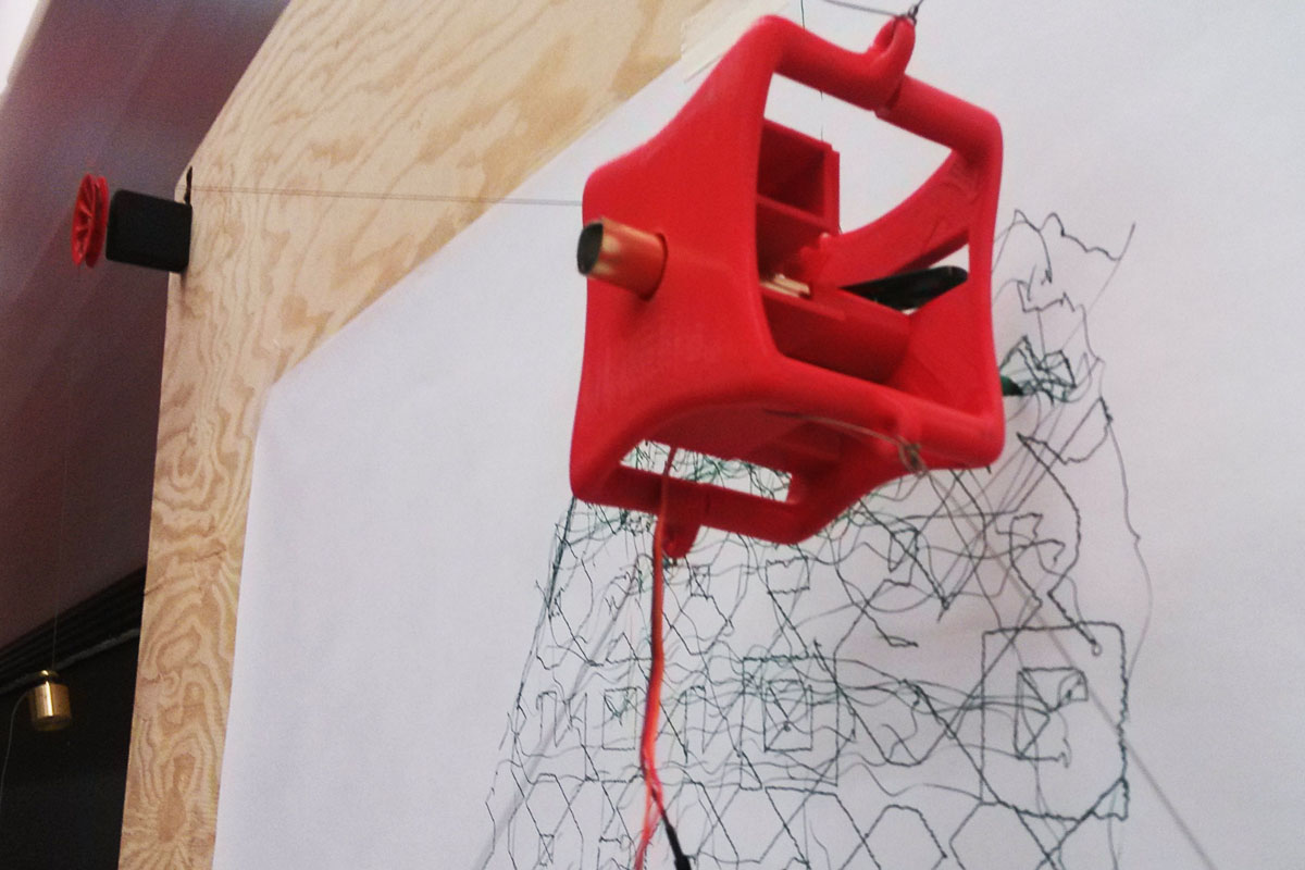
This was the first test trying to get the wall plotter to draw a pattern input as Rhino curves in Grasshopper. The precision was actually better than I expected for a first try. I accidentally started the tool path when the carriage was a bit too high. So the scribbles essentially represent where the carriage was unable to draw the pattern as commanded because it reached the limit of its workspace.
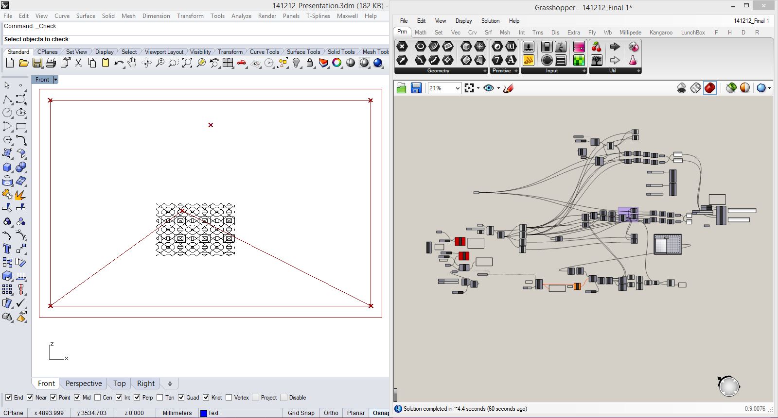
This screen shot shows the input pattern in the workspace in Rhino, and the Grasshopper definition parsing those curves and turning them into stepper motor commands. The Grasshopper definition being used to control the wall plotter motion can be downloaded here.
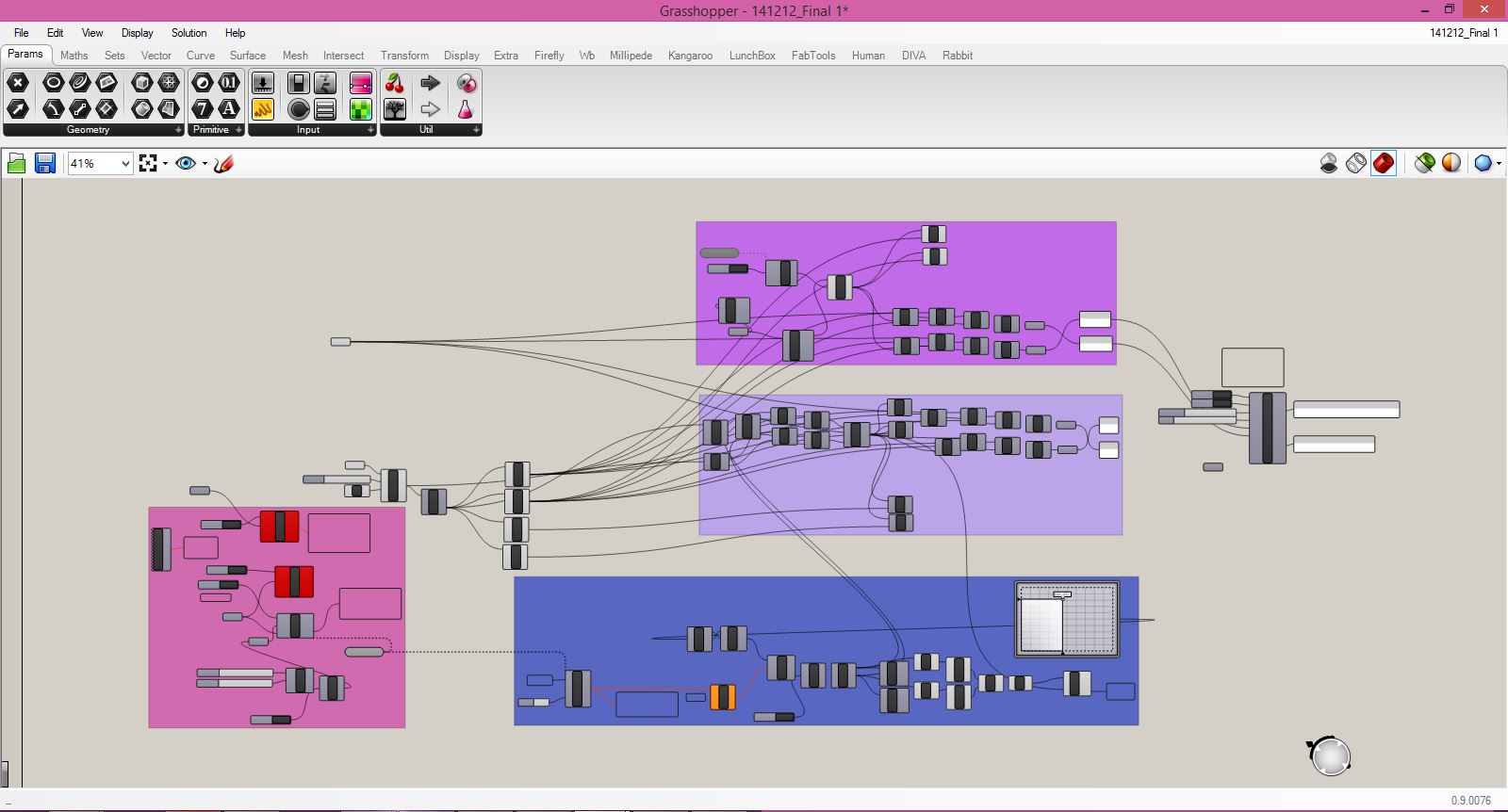
Here's a closer look at the Grasshopper definition. There are two operational modes included in this definition. One (shown in purple) allows the plotter to follow an imported toolpath, while another "doodle mode" (in lavender) reads OSC commands from an Android app (Control OSC), as was described in my Applications week assignment two weeks prior. The pink group on the left reads the serial monitors and opens the correct ports (using Firefly components). The blue group at the bottom processes commands for lifting the pen off the canvas and putting it back down. Finally, the components on the far right stream the formatted stepper motor commands to the motor drivers.