The week started with a really nice tutorial from Nadya Peek, who helped to clarify things on a more conceptual level. Unfortunately, it seemed there were more resources available for Linux and Mac users than there were for Windows. However, there are a number out there. I mainly referenced tutorials from Andrew Mao for general setup and C coding for windows, and Jonathan Grinham as well as the Fab Academy for Arduino setup and programming.
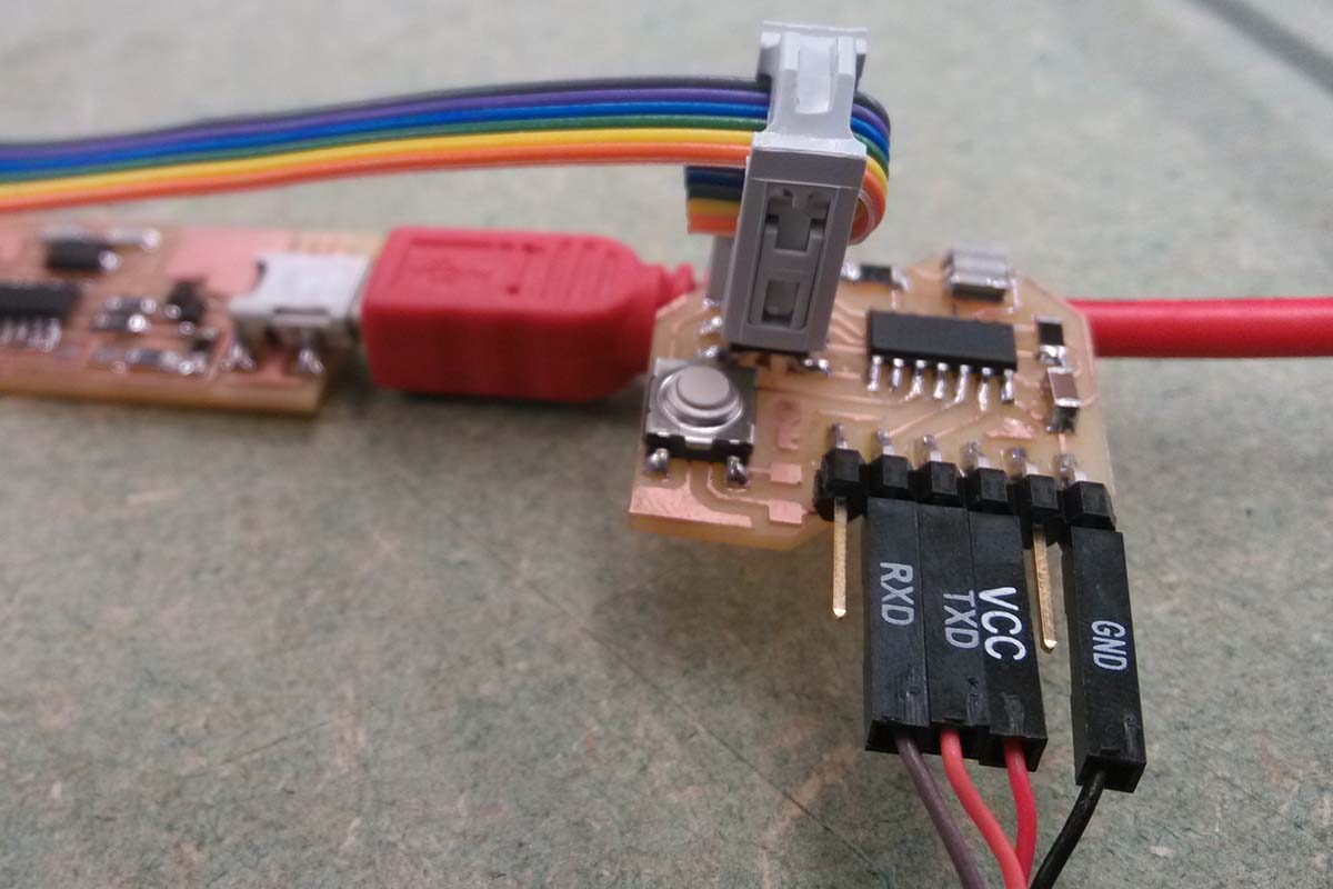
I was fortunate in that my circuit worked correctly from the beginning, so I did not need to do any refabricating or even editing of the board, and was able to focus on software (which is good, because it was much more time consuming than expected).
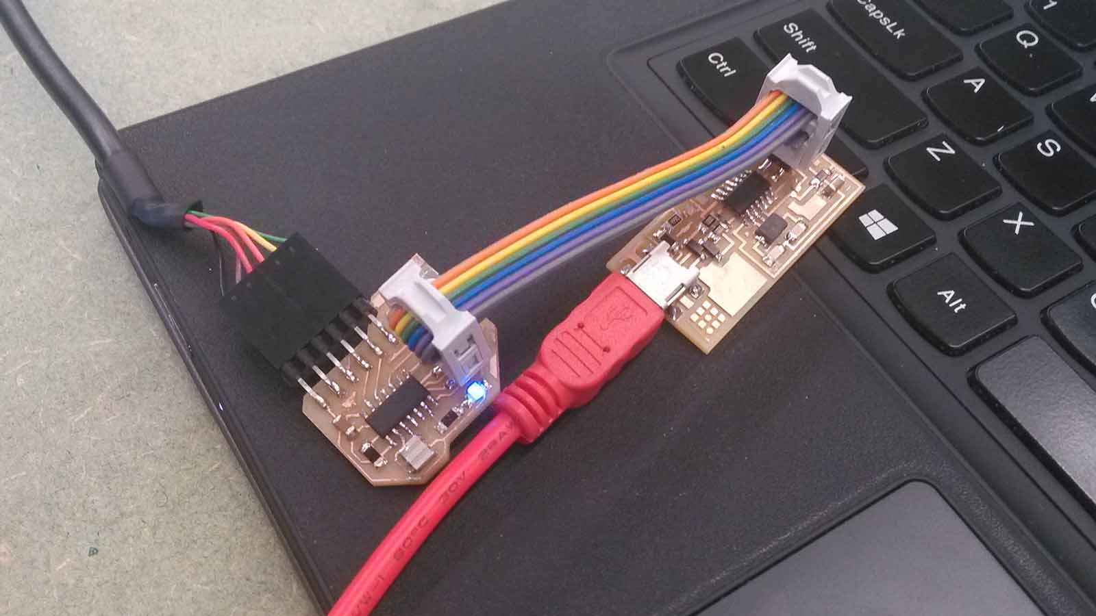
The first thing we did during the tutorial was to test the term.py script that Neil had written to listen to the echo code. This worked on the first try using my board and ISP. Unfortunately, it had to be programmed from another computer since we hadn't found a working solution for Windows yet.
One of the first obstacles I encountered this week was due to my recent involuntary upgrade to Windows 8.1, causing this failure to initialize (see cryptic/morbid error message below). A quick search revealed that I was not the only one with this problem. I was able to solve it by downloading a new .dll file posted here.
avr-gcc -mmcu=attiny44 -Wall -Os -DF_CPU=20000000 -I./ -o blink.out blink.c
avr-objcopy -O ihex blink.out blink.c.hex;\
avr-size --mcu=attiny44 --format=avr blink.out
0 [main] sh 8112 sync_with_child: child 6188(0x168) died before initialization with status code 0xC0000142
1370 [main] sh 8112 sync_with_child: *** child state waiting for longjmp
/usr/bin/sh: fork: Resource temporarily unavailable
make: *** [blink.hex] Error 128
We tried using Atmel studio, which I found to not be particularly useful, and then managed to get WinAVR to work instead, just running commands via avrdude in the command prompt. I started with the makefile for the .echo code (just as it was provided, though I later got comfortable editing them). Then, using the provided echo.c code, I used the makefile to compile the code and then convert it to hexadecimal for uploading. This is done simply by typing the following:
make -f hello.ftdi.44.echo.c.make
Or, if your makefile is called "makefile" in the specified directory, you can simply type "make". Next, since it was my first time programming that board, I needed to set the fuses. This only needs to be done once.
make program-usbtiny-fuses
Finally, we need to actually load the code onto the board. If the previous two steps have been configured successfully, this is the only step you need to repeat for any subsequent changes to the code.
make program-usbtiny
Finally, check the echo using the serial port connection window in python (term.py). This required me to uninstall Python 2.7 for 64 bit Windows and reinstall with 32 bit, then install PySerial. Finally, it worked on my computer.
So, the next step was to follow the same process with the LED Blink code. Using the blink.c and blink.make files, I was also able to do this successfully, apparently, though the LED didn't blink. After carefully checking the code, it turned out that I had specified PORTB when actually I should have specified PORTA. One useful trick for debugging this was to set all of the pins on PORTA high, to see if those connections are working. This is done using the PORTA = 0xff; command within the while loop. So it should look like this:
while (1) {
PORTA = 0xff; //(this is the only line added to the default code)
// turn led off
clear(led_port, led_pin);
// wait 100 ms
_delay_ms(100);
// turn led on
set(led_port, led_pin);
_delay_ms(100);
}
This basically overwrites the clear, set, and delay and just forces all of the pins high. This made the LED turn on, so I knew it wasn't a hardware issue. Then, further inspection showed that I just needed to change to PORTA instead of PORTB, so that the C code defines looked like this:
#define led_port PORTA
#define led_direction DDRA
#define led_pin (1 << PA7)
After making this change and reloading the code, the chip's LED blinks at 100ms on then a 100ms delay. As exciting as that was, I set about trying to add complexity to the C code. I first started testing different random value patterns within the while loop. For example, something like this:
while (1) {
// turn led off
clear(led_port, led_pin);
// Generate a random value
int y = rand();
int x = y*0.01;
// wait 100 ms
_delay_ms(x);
// turn led on
set(led_port, led_pin);
_delay_ms(100);
}
Which would flicker the LED at random intervals. I tried a number of variations on this theme, thoguh I was quickly growing frustrated with C and how fussy it was about variables. I wanted to simply fade the LED in and out using Pulse Width Modulation, and referenced Andrew Mao's excellent tutorial for that, though I couldn't really figure out how to make it work for me with just one color LED. After I was sufficiently sure that I had hit a wall, I moved onto Arduino.
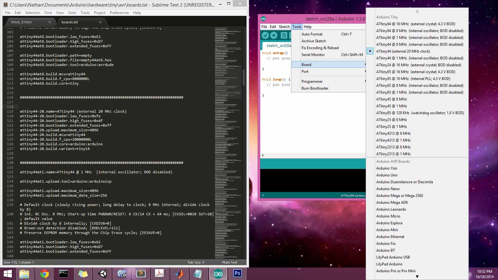
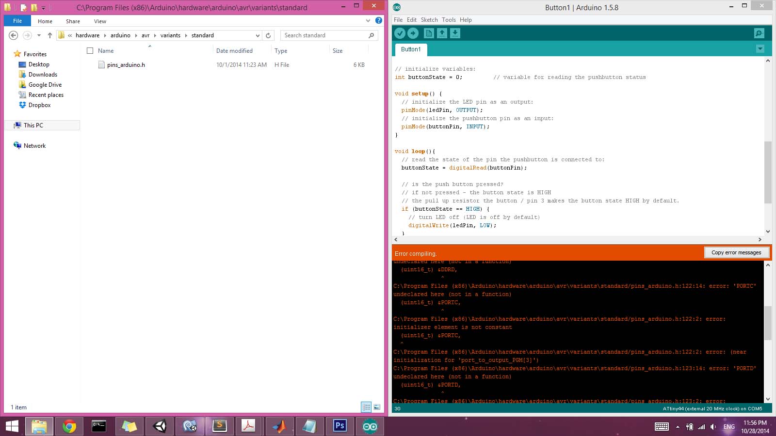
The setup process for the Arduino environment proved no less fussy than the command line and C coding process. First I had to download and install the Arduino IDE, install the FTDI libraries, and then edit the .board files. Ultimately, I think I still did not get this completely right, as I kept running into errors trying to send the Arduino file to the board. I copied the text below into the .board file in the hardware folder, which allowed me to select the board in the Arduino environment.
attiny44-20.name=ATtiny44 (external 20 MHz clock)
attiny44-20.bootloader.low_fuses=0xfe
attiny44-20.bootloader.high_fuses=0xdf
attiny44-20.bootloader.extended_fuses=0xff
attiny44-20.upload.maximum_size=4096
attiny44-20.build.mcu=attiny44
attiny44-20.build.f_cpu=20000000L
attiny44-20.build.core=arduino:arduino
attiny44-20.build.variant=tiny14
However, I think the issue is with the last line, where it looks for a build.variant.