Background, or ambitions
This week I came across several drawbot examples on Internet. I love the “unstableness” of the machine. It sits between machine printers and handwritings. My ultimate goal is to make a drawbot.
Drawbots have different implementations. The most high resolution and high-end one I found is Polargraph. Surprisingly, the tiny guy hanging there draw the picture by himself.

There are other variations of drawbots. Here is a ‘weekend project’ of Make magazine using servo motors. It is amazingly controlled by an audio outputs. Not PWM but audio wave will control the motors.
TRS Drawbot (Make: projects) http://makezine.com/projects/trs-drawbot/
However, making a drawbot this week would be too ambitious. I will start from controlling a stepper motor - for this week BYJ48 unipolar, which I saw is used in several drawbot examples.

BYJ48 Stepper Motor
Design the controller board
I first tried to use ATmega this time. There are two arrays of MOSFETs which control two unipolar motors. I used two FTDI connector pads to connect to the motors with four pins. One 2x3 connector is for FabISP programming, the other is for power supply, which is a 9V battery. I used low pass filter between VCC and GND after decreasing the voltage from 9V to 5V for ATmega. BYJ48 directly get supplies from a 9V battery.

Schematic Design
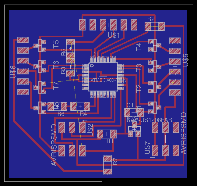
Board Design
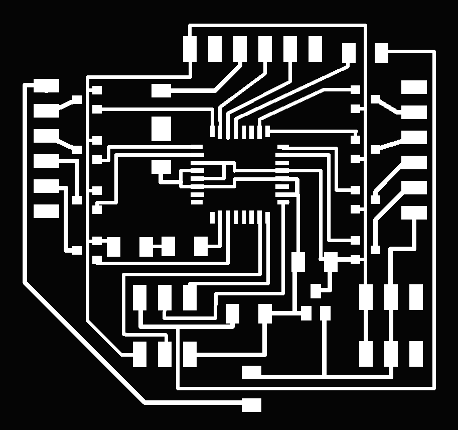

Exported .png images
Mill the board
When I exported the image in .png with 500dpi, I realized that I cannot generate paths which can mill the pads correctly for ATmega. Several pads are connected together. I can divide these pads if I input smaller tool diameter, but it seems too small.

Calculated paths on fab module
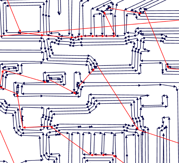
Zoom in on the ATmega pads
Unfortunately I ran out of my time this week for further troubleshooting. I tried to mill the board with smaller diameter later but it did not work.