Input Devices
Four Buttons on a Board
|
Week 10
Input Devices Four Buttons on a Board |
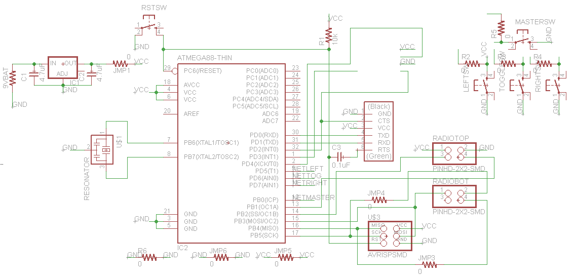
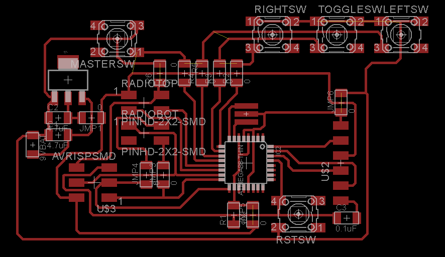
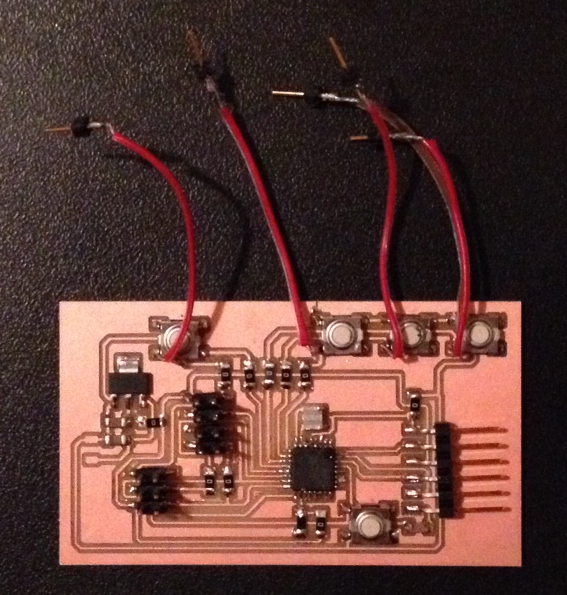
| For this week's assignment I went the simple route, and made a board with four buttons on it. The microcontroller at the heart of it is an ATMEGA328P, and each push button has ground on one lead, and one of four microcontroller pins (PB0, PD5, PD6, PD7) on their other lead. The resistors in the schematic are not pull-up resistors but 0-Ohm jumper resistors, because each of the input pins has an internal pull-up resistor that can be enabled. This makes the board layout simpler. The board contains various such 0-Ohm jumpers labeled JMPx. It also contains a 5V regulator (LM1117) with input voltage supplied by a 9V battery (drawn as a resistor just for the sake of having some solder pads). The battery and the FTDI cable must obviously never be connected at the same time! |
|
|
| See the page on the final project for more details about how this board is used! This board also contains an eight-pin header for connecting to a wireless radio and broadcasting the state of the buttons. This is described in more detail here and here. |