Final Project
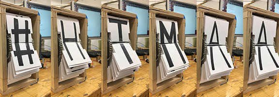
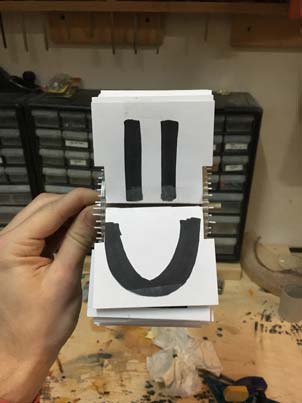
A prototyped split-flap display.
The Idea
I've had the idea for quite some time to build a split-flap display for my house. Instead of announcing the times of arriving trains, my split-flap would display live messages tweeted (or otherwise messaged) to the machine. What always held me back were the electronics and the programming side of things, as these were the most expensive and the most complicated. But through this class I finally got the chance to give it a shot!
The Design
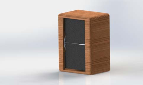
I began by using SolidWorks to model up the full display. I had to figure out how big the housing would have to be to fit the cards, and to rig up the card wheel so that they would be able to fall easily when the wheel turned. I figured the motor would have to be geared down since the torque on a cheap bipolar stepper isn't typically very high. I found a ton of information to help me through the project from Unknown Domain (a designer in the UK), and The Beach Lab (one of the global fablabs from this class). The Unknown Domain display was built for a storefront in London and the page I found documented very well their process of design from prototyping to the final product. From the Beach Lab documentation I was able to pull more on the software side of things. Reading through their GitHub I was able to see how they drove the motor to land at each character.
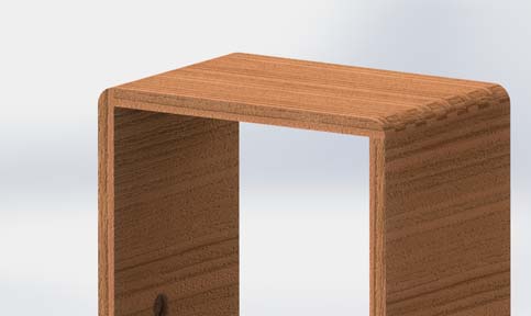
With the CAD near finished, I met with Justin to discuss how to fabricate the housing for the display. I wanted to make a nice rounded, wood, finger-jointed housing for the final product, so we discussed how this would be possible, and the process for doing so (documented below). I realized fairly quickly that I wouldn't have time to complete the project and make it look that perfect, so concessions had to be made.
The Mechanics
Once I had the mechanism designed, I had to order the parts from McMaster in order to build it. I decided that I would use a hex rod as the shaft in the frame, which would be allowed to spin by some bearings placed in the support holes. This would ensure that my sprockets and wheel would turn with the shaft instead of slipping. I had a few bipolar stepper motors laying around from an old project, so luckily I didn't have to order those. I waited a few days for the package to arrive so I could start building, and worked on the electronics in the meantime.
It turned out that I had ordered the wrong timing belt to match my sprockets, so I had to go back onto McMaster to find the correct one. I did this, and ordered some acrylic for the wheels, and a round shaft to replace the hex (I could just find a way to secure the sprockets and wheels in place). This delayed the build process even more, and is what disallowed me from creating the much nicer frame that I wanted.
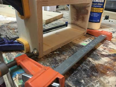
Towards the end of the week I was finally able to get the housing cut. I used 1/2in MDO plywood, and ripped some lengths of it to 3" wide to make up the frame. I cut these to length (2 at 5.75" and 2 at 4.5") using a chop saw next. I decided I would hold of on creating the face plate until I knew that the mechanism actually worked since this would be an even more time consuming process. Once I had all of the frame pieces I had to drill out the holes for the shaft to ride in. I used a Forstner bit to drill about half way into the wood, wide enough to allow the outer diameter of the bearing to fit snugly.
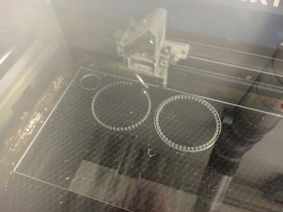
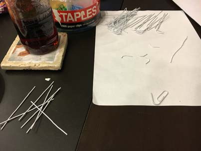
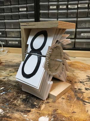
With the frame ready to assemble, the next step was laser cutting the wheels to hold the cards and the motor mounting plate. The wheels are simply a 3" diameter circle with a pattern of 50 .1" diameter cirles around the edge. The motor plate was designed to match the mounting holes on the face of the motor, and include slots for adjusting the tension in the timing belt. Once these were done I also had to create all of the cards. I decided to go with 50 characters (for reasons discussed in the electronics section), and with time I would have liked to laser cut these from a thin plastic and use the vinyl cutter to create the letters. But I simply wrote the letters on card stock and using paper clip wire as the shaft for each card for ease of production (after all, it is just a prototype). The center wheels were glued on either end of a short cardboard roll for structure, then the cards were slid into the correct slots onces it dried. The wheel works great! Ideally I would include less cards in the final model, I didn't account for them stacking up against eachother as much as they do.
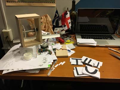
When it came to assembly I faced some real difficulties. First of all, the shell was not dimensioned correctly, because I forgot to take into account the cards that would be hanging below and behind the wheel. With that, the box was too short and the motor wasnt able to be mounted correctly. I was able to mount the motor eventually (albeit not nicely) on the outside of the box, but not in the same adjustable fashion as I would have liked. Tensioning the timing belt to the correct degree is therefore quite difficult, but it is in a close enough position to function.
The Electronics
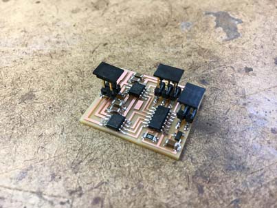
I started by producing Neil's bipolar stepper board to simply drive a stepper motor that I planned to use to test the display. I needed to do this in order to find out how many steps it would take to switch between letters. I ran into all kinds of issues just trying to build this board. I milled and stuffed the board pretty easily, but it got tough when it came to the programming. See Project 8 for more information on the development of this board
Once I was able to get the motor spinning it was all in the code to attmept to calibrate it. I ran the motor a couple of times with a fresh battery to try to determine the number of steps that made up a full rotation. I found that 50 steps seemed to make a full rotation based on this simple observation, so this is how many cards I decided to make to simplify the process. This way each step corresponded to a different letter, and in a perfect world one would only have to tell the motor to move the number of steps between each character to spell a word. This wasn't the case after testing, however, so I created a function in the C code that would allow me to change the amount of steps the motor took per card step in order to attempt to get the display to spell out words. Because of the low torque of the motor and over-tensioned design however, this process is still not entirely accurate. The motor just seems to spin randomly trying to reach its appropriate position each time a new character is read.
I was still working on another board that would be able to interface with the python code to change the character string with user input, but wasn't able to get it done in time as I was trying to get the machine to work in the first place. So in the end I just ended up having to use Neil's board.
The Code
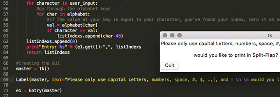
The C code that drives the motor is a derivative of Neil's basic full turn code. I added a function that would allow me to set the amount of defined motor steps between letters fairly simply, and then a loop that would cycle through the indices of the characters typed in by the user (with a two second pause between each letter). I wasn't quite able to integrate the python script that I had written for the interface, but the foundation is in place.
The purpose of the Python code (see Project 10) is to allow the user to type their phrase into a nice UI, and then translate that phrase into a list of position indisces to be read into the C code for positioning of the display. It works by accessing the ASCII table and inserting a few additional characters into the gaps to form a dictionary to reference for the key/value correlation between the typed characters and the positions on the wheel. The python code section functions great! And integration is coming soon, along with a number of other things.
C Code
Python Code
The Components
Python Code
The Components
The Components
Electronics wise, everything was available from the fab inventory. While I had worked on designing a different, custom board, I only ended up having enough time to machine and use Neil's example bipolar stepper controller.
I purchased all of the mechanical hardware (besides the wood) from McMaster-Carr at an approximate price of $40. This includes additional components purchased for tweaking along the way, so the actual cost would probably be around $20-$25 per module in the end.
The Wrap Up
In the end I guess I learned a lot about what needs to be changed to manufacture the final split-flap. I will definitely be finishing the project at some point, hopefully with a number of modules to spell out full phrases without just having to scroll between letters. I've figured out a more reasonable estimate of dimensions for the housing, and what exactly I'll need to do to make the final modules look more professional. I will definitely revisit the CAD and try to get some accurately dimensioned models to create the housing I designed intially as opposed to the prototyped one produced. When it comes to the drive train, I will need to integrate a simple belt tensioning mechanism to tweak the motor control once everything is secured in place as opposed to trying to do so with all of the parts flying around. Actually laser cutting the cards from a thin plastic and vinyl cutting the letters will also help with appearance and mechanics as the main wheel will be more predictable and reliable. I'll be able to tweak the code once I have a more accurate mechanism, but ideally I'll also be able to include a component to sense position of the shaft instead of relying on shear accuracy of the stepper to get the cards to fall in the right position.
All in all, I'd say that the project was moderately successful. There are obviously a large number of things that I had wanted to integrate but wasn't able to, along with a number of things that just didn't function correctly, but I'm a lot closer to a functioning split-flap display than I was before this project. The main take away here was the experience. I've had this idea for years and just never thought myself capable of carrying it out to fruition. After this class I feel confident in my abilities to integrate all of those items that I wasn't able to before, in order to make this dream a reality after all.