
This is a continuing series on my final project. If you are interested in starting from the beginning, you should start at output devices and follow on to input devices before reading here.
This week I wrote a Mathematica notebook that interfaced with the input device that I created last week. This program allows you to see in real time which switches are open and which are closed. There are two functions to having such a program. 1) It allowed me to spot check to make sure the switches were synced properly to the physical spaces in the multiplexing board 2) the serial link would allow me to capture every state change of the game if I desired. This is potentially really cool because it could automate annotating games. Something that every player dislikes doing.

I love Mathematica. I know that it is outside the norm of maker movement, it being closed sourced and pretty expensive, but there is a lot of benefit to the flexibility and abstraction that the program allows. I have used Mathematica in every class requiring math that I have taken at MIT and am constantly surprised to find functionality that directly suits my needs. This week was no exception.
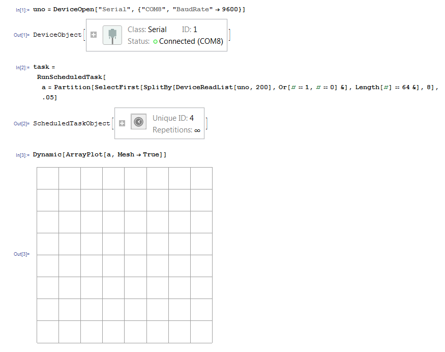
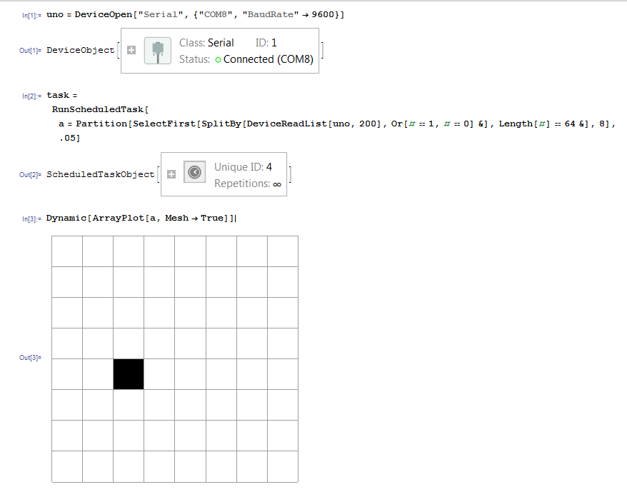
If you have been paying super close attention to my development of the chess board over the past few weeks, you will have noticed that I inserted into the output device sketch some code that sends the state of the board over the serial connection. This data stream is interesting because it is one dimensional. I.e. the computer only gets a stream of 64 bits without knowing how those are arrayed in 2 dimensions. Hence the program that receives that stream must understand how to parse it in order to turn it into a usable diagram for our purposes.
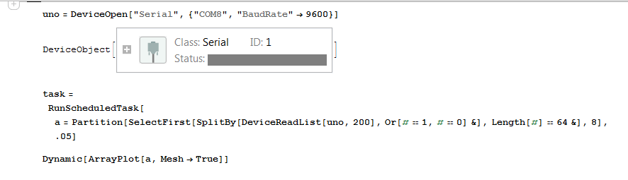
I wrote the notebook to grab two hundred of the bytes (whatever happened to be coming into the port at the time), to then cut out the first 64 bytes that were 1s or 0s and then partition that into an 8x8 array. I set that program to run on loop every fifth of a second and then update a little graphic that reads the array and gives a black space if the space has a piece and white if it does not.
This code could easily be adapted for the annotation function. Take a capture of the state every fifth of a second, compare it to the last capture: if it were different, update last capture and store this one in memory. Given that record (and that all the pieces started in the correct spots), it would be pretty trivial to write a program that translated the record into an annotation.
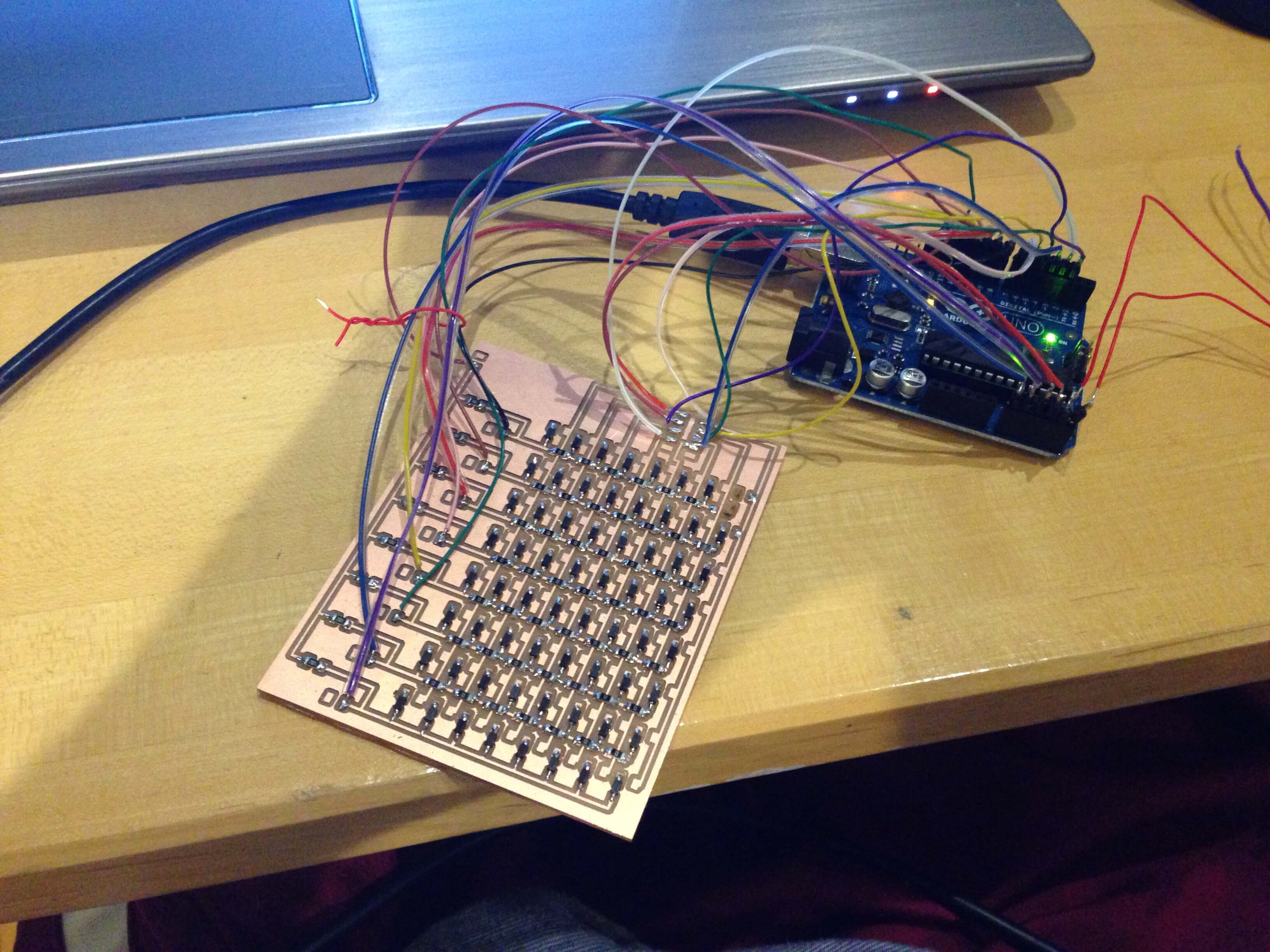
As simple as this was, it was rediculously useful in troubleshooting my connections and setting the debounce timer.