
In output devices I talked about my decision to focus on creating a chess board that automates the action of switching a timer in a blitz chess match. For this week I want to focus on the switching mechanism that will be used to communicate to the board.
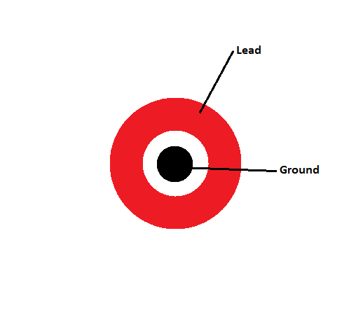
Out of naivety I thought that this would be a place where I could use capacitive touch to do this. The general idea was to put a capacitive sensor on each square (n=64) and then multiplex the array for detection. I am not sure that this would not work, but after a long discussion with one of the TAs they convinced me to try the same scheme with traditional switches. Then I had the cool idea of creating putting two copper pads on each of the squares in a configuration similar to this.
I again decided that my chip would be a fabable Arduino and I would build the multiplexing portion of the board independently. We will break this section into the Arduino portion, where I faced my most frustrating time in How to Make. And the multiplexing board, which was very satisfying.
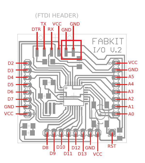
I again milled the Fabkit, stuffed the board and then went to burn the bootloader. When I pulled up the bootloader I would get my computer to recognize the board and then was able to burn the bootloader, but when I disconnected the programmer and tried to load the program through the FTDI cable I would get
Skt500 get_sync() not in sync
This is where I got bogged down. I spent roughly 10 hours googling and trying to fix my board. If you encounter this problem I hope to save you some time. First, the most common cause of the error function is that you have selected the wrong board or the wrong port to communicate with the board. The insidious thing about this error though is that a number of different things can cause it and some of them are quite subtle. Here is a good reference if you are intent on troubleshooting the board.
I was unable to get my first board working. Or my second. In total I spent 20 hours trying to get the two boards to program after I had the bootloaders loaded on both of them. I talked with some of the TAs and the general consensus was 1) we had no final answer to what was causing the error 2) we thought it might have to do with the fact that the CTS# pin remained grounded rather than being hooked to a pin. Dan Chen mentioned that this pin is specifically for synchronization, so it seems likely that’s the issue.
Regardless, here is my advice. If you get the error (and its not something obvious, like you have put the wrong instructions into the Arduino ISP) remake the board. Spending more than an hour troubleshooting a simple board for this error is not value added time. As it happens, after the class is over I intend to edit the fabduino to connect that pin and see if that fixes the issue. I just didn't have the time or the capacity to troubleshoot a modified board.
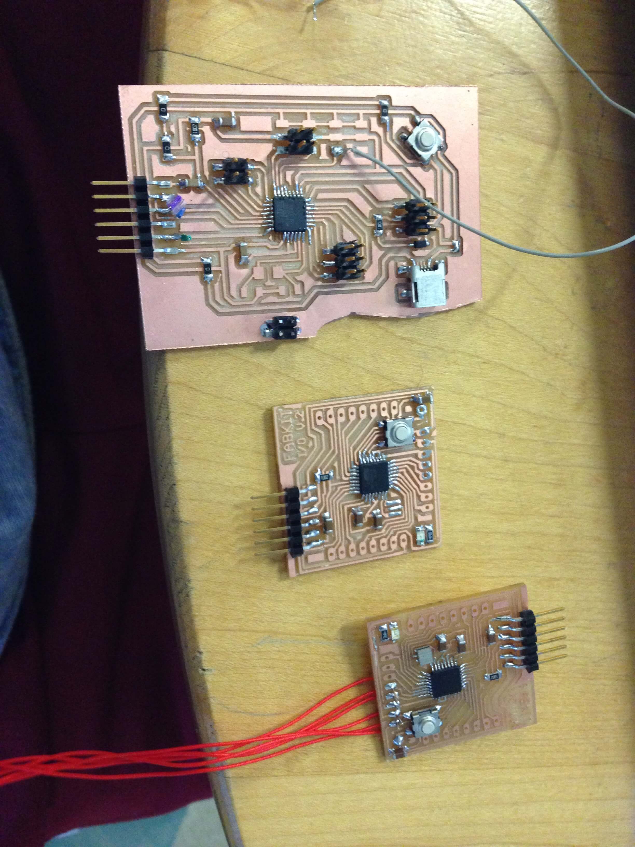
I moved on directly to making Dans board, but figured out after making it and programming it (it worked!) that it did not have enough pins for my purposes - my multiplexer required 16 pins and I needed 2 pins to communicate with the LCD Arduino from last week.
So, I admit, I compromised and borrowed an Arduino Uno from a TA that took pity on me. I understand this is not in the spirit of the class, but after 30 hours of board building and troubleshooting I could not justify spending any more time on something I had already done successfully.
The next step was to design a multiplexer that could handle the 64 switches I was going to hook up. With more help from the TAs we decided on a very simple design. The rows would be hooked to output pins, the columns linked to input pins. Then in the code we would nest two for loops. The outer loop would bring a row high, then the inner loop would sample each column to see if the switchers were open (piece not present) or closed (piece present), then the outer loop would bring the row low and it would iterate.
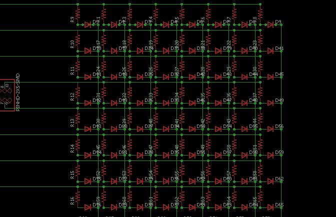
Here is the board and schematic. Warning for this: they are not in sync. It was going to be a huge pain in the ass to manipulate each component into place after building it with the schematic so I hacked it by just drawing everything in a separate board file. Sorry, I know that sucks, but I was working for efficiency and it was a simple board. There are probably techniques to do both at once, but none I knew or had time to search for. (As an aside, I find eagle has surprisingly little documentation).
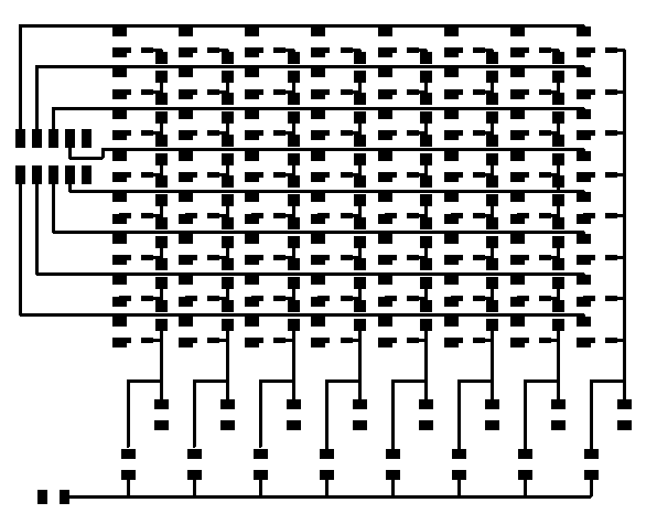
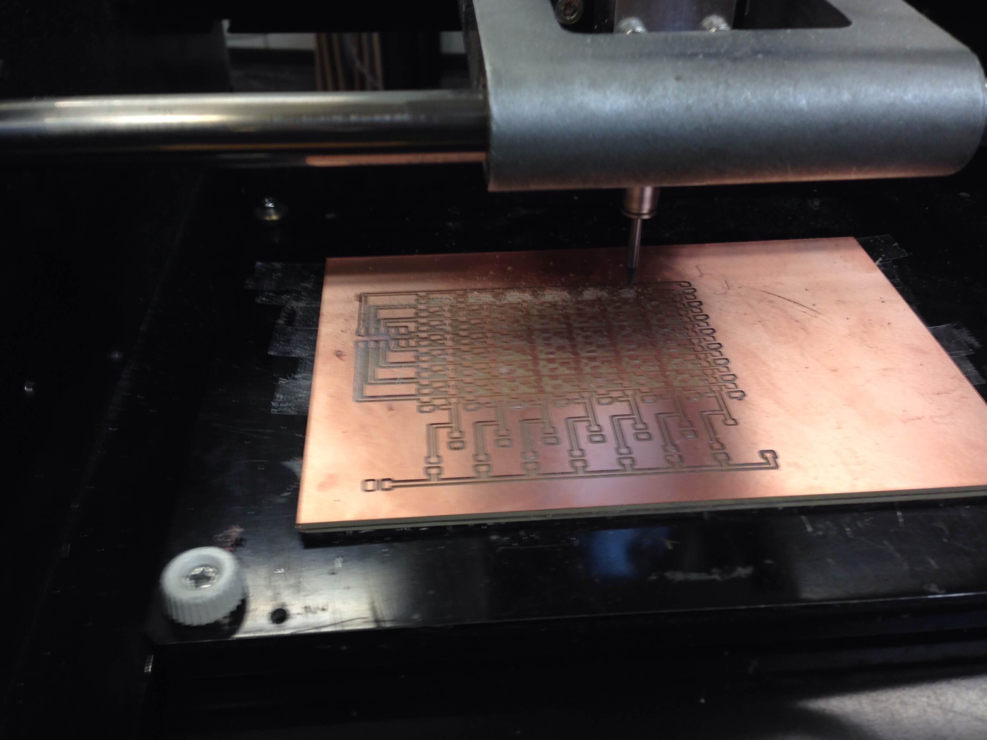
Milling and stuffing went well.
The final step was designing the program that would actually sample the traces correctly. I proceeded with this in three steps.
First, I wrote a simple sketch that would bring a row high and allow me to check that I had everything matching up in physical space and program space.
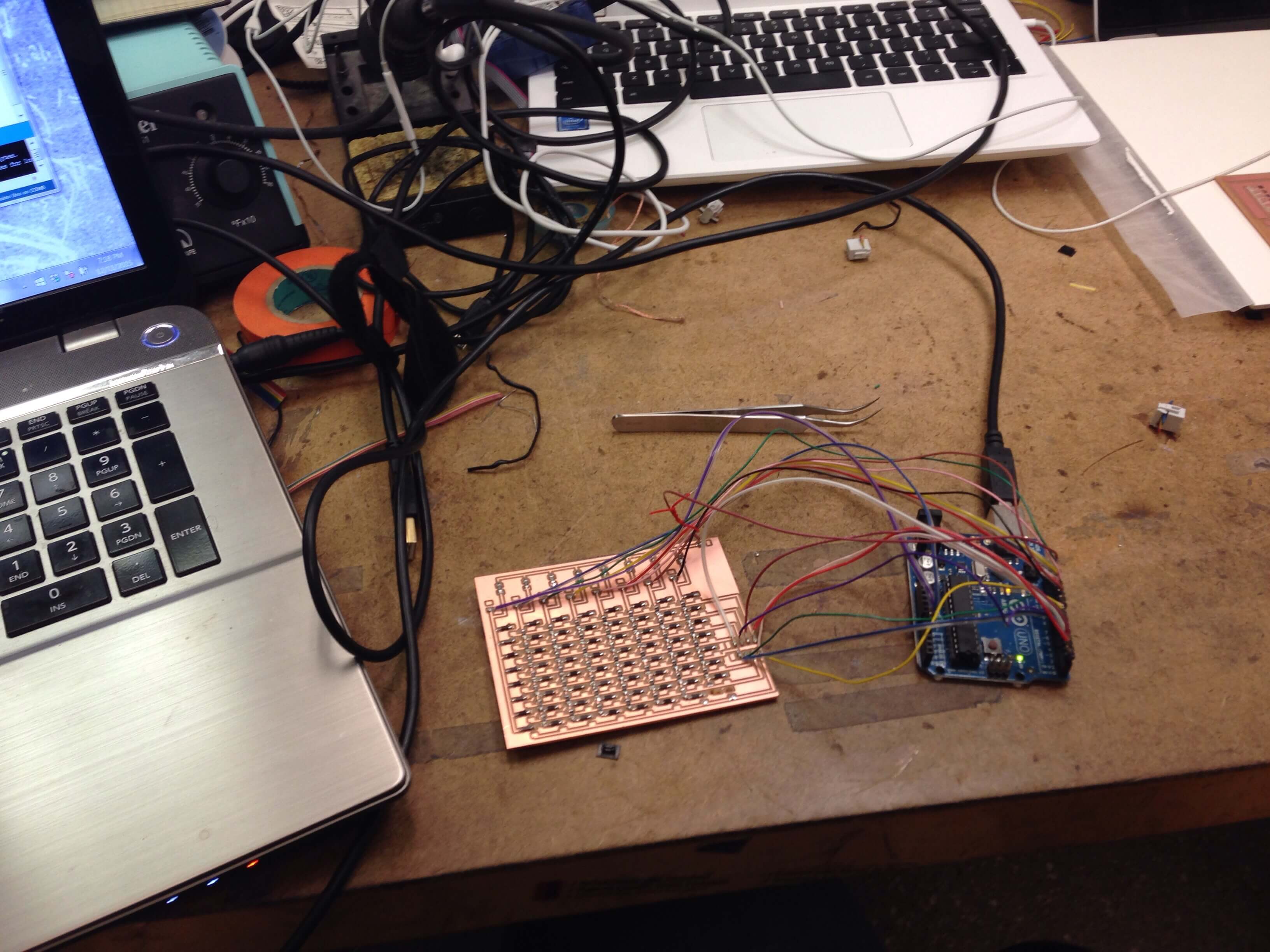
Second, I wrote a sketch that would do the simple nested loop that I discussed earlier. I combined this with my serial project (next week) to test that the switches closed and that the board was detecting everything.
Third, I incorporated code that would also debounce the switches. Debouncing is an interesting problem that can be solved in a number of ways. I have linked far and away the best simple reference I found. I opted for a construct that did the debouncing without a delay as recommended by the ever helpful TAs and was able to get it all together in a final sketch that I tested with my serial connection.
Joy is a project that works.