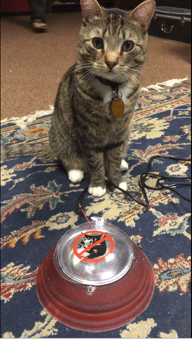
The purpose of this final project is to make my life and Rupert's life better. The Problem: Rupert is not allowed to eat dry food for the good of his own health. Similarly, when he eats Evie's (the other cat we live with) food, Evie's owner gets sad, because then Evie does not eat. The Solution: The Selective Cat Bowl, or the "NO RUPERT! Don't eat that!". Each cat will have their own collar device which will pulse an IR LED at a unique frequency. The IR Receiver on the cat bowl will sense which cat is present and wants to eat. If Evie's cat collar is sensed, the bowl with open via servo rotation. If Rupert is around it will remain closed. However, if Rupert shows up and tries to steal Evie's food while she's eating, the bowl will close until Rupert has been extracted from the situation.
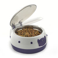
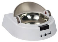
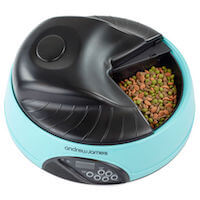
Now, this is not a novel idea, people have been making technology for their pets forever! However, these types of things are generally somewhat niche and fairly expensive, approximately $150-200 for ones with good reviews. Based on reviews there are also a couple of issues with either having an ID tag for the cat that is too bulky, having the lid close on the cat or scare the cat away from the bowl, or having an opening for food that is not big enough such that their whiskers get caught and the cat is sad. Taking all this in mind, I gave my shot to creating a bowl that would attempt to resolve some of these issues.
The "NO RUPERT! Don't eat that!"- Selective Cat Bowl
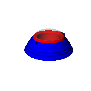
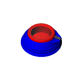
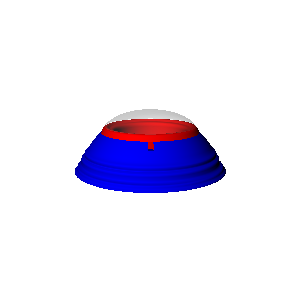
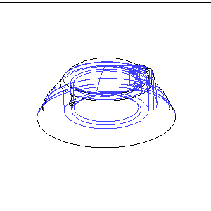
HTM Final Project- Selective Cat Bowl by chenrot on Sketchfab
Of course, as one should do with most projects I made a basic list of all the tasks that needed to be done such that I would actually be able to make this happen in the alotted time. Here it is: 1. mold & cast outer bowl -design mold -glue foam -mill mold -post-process -fix mold walls -oomoo -cast 2. mold & cast inner bowl -design mold -glue foam -mill mold -post-process -fix mold walls -oomoo -cast 3. mold/ vacuum form dome -design mold -mill -coating/ post-process -vacuum form -cut to size 4. input output board -design it -mill it -stuff it -code it -wire it 5. led board -design it -mill it -stuff it -case it with battery 6. vinyl cut sticker -design -cut 7. DOCUMENTATION Bill of Materials: -Foam for molds (lab inventory) -PCB and components (lab inventory) -Servo (lab inventory) -Plastic for Thermoform (lab inventory) -Oomoo $80 (paid by me) -Smooth-On Plastic $25 (paid by me) -Vinyl & Transfer paper (lab inventory)
Molding and Casting Inner and Outer Bowls
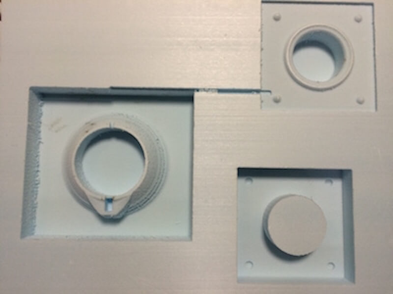
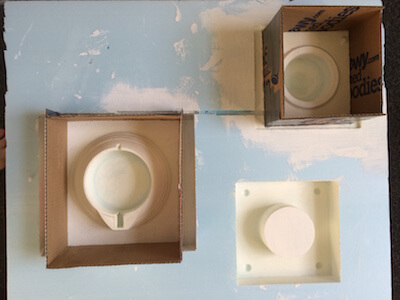
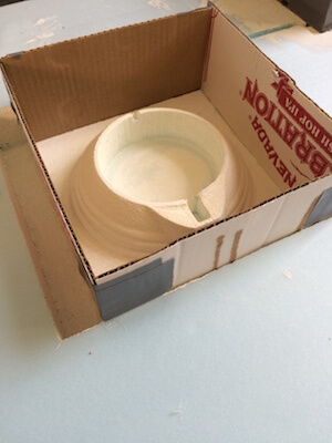
Like molding and casting week, I wanted to make a flexible mold to cast a plastic part that would be my bowl. This entailed milling a positive mold out of foam, casting oomoo to create a negative flexible mold and then casting plastic into the oomoo. I thought it would be a pretty straight forward process, but there were a lot of differences in this process as compared to the molding and casting week.
These include: different materials for positive mold, size differences, and casting material differences.Here are the models
HTM Final Project - Outer Bowl Mold by chenrot on Sketchfab
HTM Final Project- Inner Bowl Mold (1/2) by chenrot on Sketchfab
HTM Final Project- Inner Bowl Mold (2/2) by chenrot on Sketchfab
HTM Final Project- Dome Lid Mold by chenrot on Sketchfab
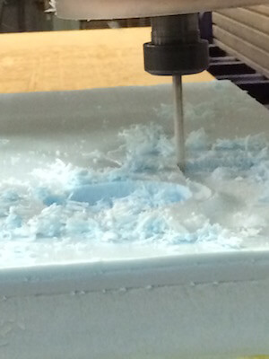
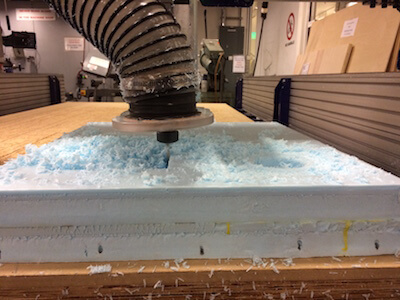
As the process always begins, I created 3D models of my molds to mill using the Shopbot and PartWorks 3D. The entire workflow was the same as in molding and casting, except for using foam instead of wax. I used a 1/4" ball nose end mill with different speeds and feeds. For both the roughing and the finishing pass I used a feed rate of 180in/min and a plunge rate of 180 in/min. The spindle speed was set to 6000 RPM. I've been told that I could have cut the foam much faster, but I milled my molds over Thanksgiving and I wanted to try and get as nice a surface finish without an outrageous amount of time. In total, milling all four molds equalled to about 4 hours prep and mill time. I did have to glue two pieces of foam together to make sure it was thicker than the thickest part of my mold models. Using wood glue and some heavy objects I did this pretty easily over night.
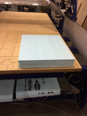
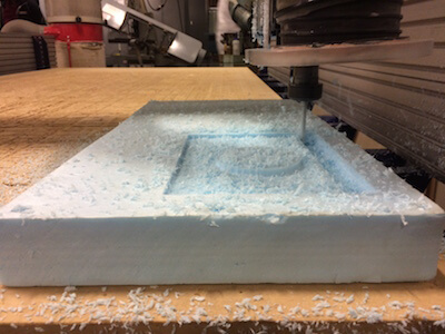

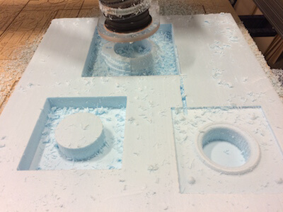

There were a few mistakes I made in this process. Firstly, I designed the molds without properly thinking about the wall heights necessary for casting. This meant that the walls were at the same height as the highest feature of the mold. Second, I designed the molds with far too much extra space around them not realizing how much material that would require for casting. In terms of milling, I had accidentally set the origin to begin in the middle of the model as opposed to the left bottom corner for the third and final mold. The tool cut directly through a part of my other mold. This didn't actually lead to a huge issues as I ended up remaking walls for my molds and that part of the mold was not included.
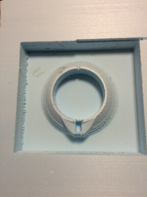
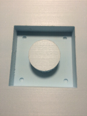
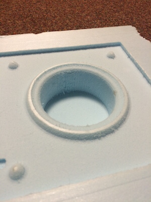
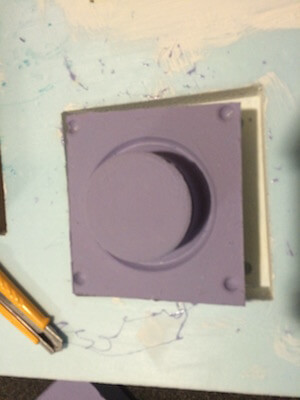
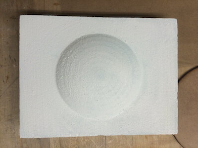
Foam is new, it's got a strange surface finish when it's just been milled. It also requires post-processing so the moisture/water of the casting materials are not absorbed into the mold. I used gesso and wax to post-process. Calvin Zhong was my expert teacher on how best to do this as he's done it so many times for his cement casting. The gesso is a sealant on the surface and the wax helps to plug up any holes as well as act as a mold release. Since the outer bowl mold was a positive I was also able to sanity check the fit of the servo that would eventually hold the dome lid.
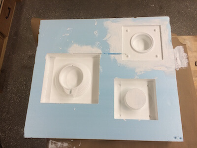
Once the foam was post processed, I needed to go back and fix the walls of my molds, for higher walls and smaller molds. I now realize that I could have made these molds even smaller. This would have been advantageous as I would have had to buy less oomoo, which is kind of expensive. Another option could be to just mill the negative of the mold originally. This I was worried about as if I broke the mold when I was demolding the bowl I wouldn't be able to cast another one if something went wrong. The other option would have been to make a mold out of cheaper material, all I knew of was drystone which seemed dangerous to use just because of how rigid it is, may also lead to having to break the mold to retrieve the part. Still these are options that came to mind as I went into the oomoo process.
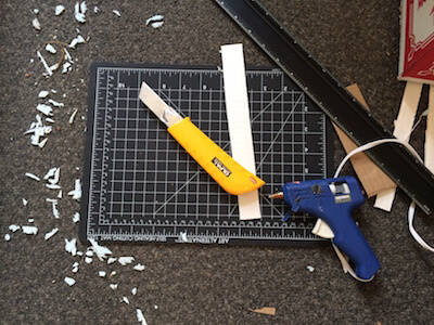
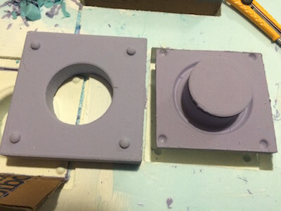
To make the new walls, I cut slots into the foam molds that were slightly less than the thickness of cardboard. I cut cardboard with a straight edge and knife to get a nice straight side. I then slotted the cardboard in and hot glued the seam on the outside. I did this for all four sides and used duct tape to seal the seams at the corners of the cardboard.
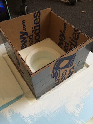
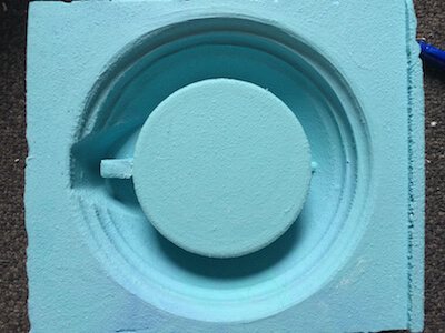
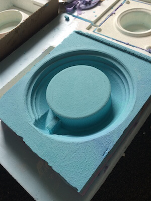
Next up? Ooooomoooooooo. I must say after this experience, I could go without oomoo for a while. I used quite a bit to fill these molds. I had purchased oomoo 25 and oomoo 30, one I ordered online the other I found at Blick in Central square. I went in with blind faith that they would stick together if it was necessary to combine them. It was necessary, but they did bond-- thank goodness. I must say my stirring job on this much oomoo was not as good, but as the process progressed I start using larger tubs for stirring and a paint stirrer instead of a popsicle stick. This made it much easier to get a thorough stir. This was the time of my first how to make final project meltdown. I wasn't sure if it was going to work casting one type of oomoo on top of another. My brain rapidly turned to panic mode and I tried to figure out if I had a backup plan. After a night of sleep, I woke up with renewed faith and it all turned out okay. I would say though that perhaps for this size of mold, oomoo is not the best option, I'd be interested to know if there's better materials for larger scale flexible molds.
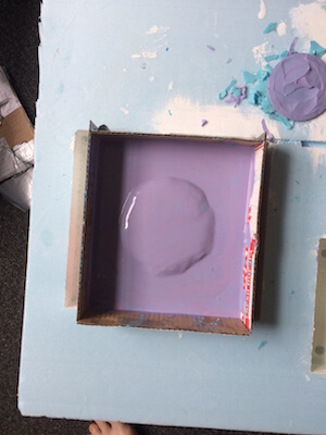
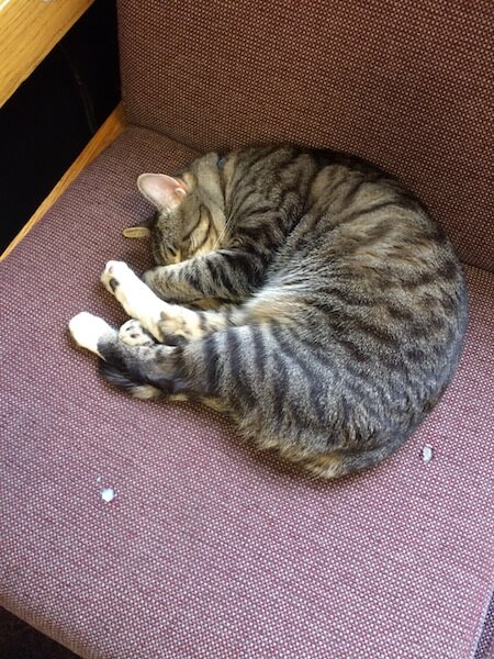
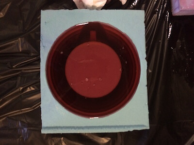
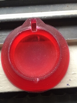
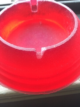
Last step, casting plastic. I was using smooth-on 326 from Reynolds with a red coloring. It required one drop of red to color the whole batch which is somewhat impressive if you ask me. Now thinking I was out of the woods after the oomoo I thought that everything would go swimmingly. Turns out this smooth-on is nothing like the consistency of oomoo, and more like the consistency of water. For the outer bowl mold, this was no issue I just filled it up to the top edge and let it sit. Unfortunately for the inner bowl, even clamping both parts of the mold, the surface finish of the oomoo was such that the smooth-on just seeped right out the sides :( sticky gooey mess does not begin to describe. Thankfully I had material down to pick up the mess easily at the end. So I decided that maybe the best would be to wait for the consistency to get a little thicker to pour without seepage. This sort of worked, except I waited a little too long and the material was just on the brink of setting as it poured so I didn't fill it as much as I'd hoped. Here is where my brain went into panic backup mode again. I considered 3D printing the internal bowl, then I considered buying more material and trying to cast again. I threw out the casting again answer because I really should have redesigned my mold to be more like the outer bowl, where I just pour the smooth-on into an open space and don't require a parting line. I started looking at 3D printing as I was waiting for the smooth-on to set so I could clean up properly. The print time would have been 8 hours and 12 minutes... not the most attractive of times considering the Ultimakers have been uneasy lately. So there I sat waiting. During this time I took a break to look at Rupert to try and reinforce my motivation for making the little scoundrel such a fancy pants bowl. He renewed my motivation without fail...
Okay motivation break over!
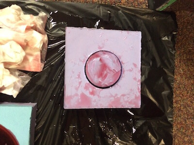
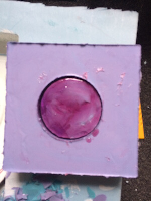
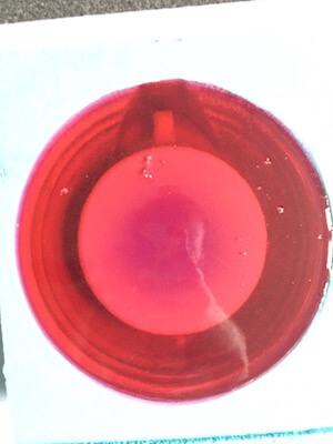
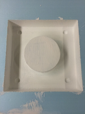
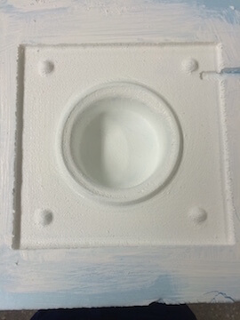
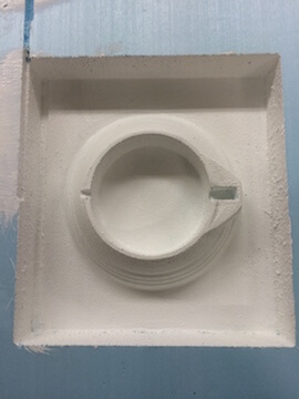
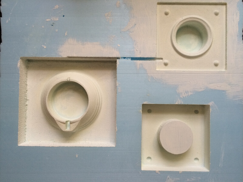
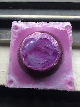
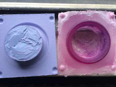
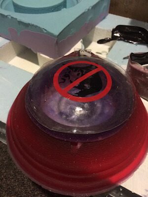
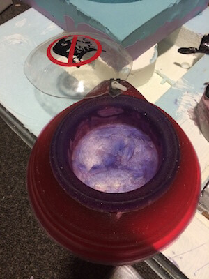
When I demolded, I was pleasantly surprised by the outcome. The outer bowl looks excellent. The surface finish isn't fabulous but that would have required a nicer surface finish on the foam mold. Perhaps heating the surface next time would help me accomplish that. There are a few blemishes as well, mostly due to air bubbles getting trapped. The technique of hitting the mold on the table to release the bubbles is sort of difficult with such a large mold. The color looks awesome though! The inner bowl, is.... passable. Or at least maybe somewhat fixable. The lip at the top looks great,I don't know why it turned purple,I used the same mixture of smooth-on. It may have something to do with not having as much material as the mold required. The bowl part is very thin, and pretty ugly, but I can probably fix it with some acrylic or plaster.
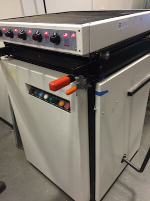
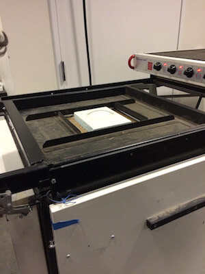
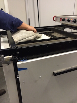
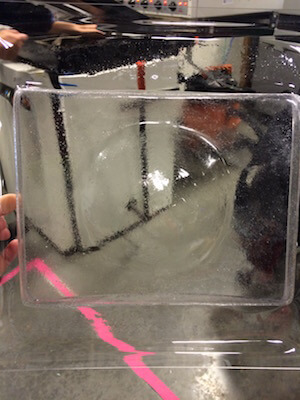
For the dome lid, I decided to use the vacuum former and my foam mold to vacuum form 1/16" PETG from the standard stock of the lab. This was the easiest process ever. Heat up the plastic until it's formable and punch the mold into the plastic. The vacuum sucks the material around the mold and then it cools. I've only ever used a vacuum former for very small parts, but it was just as simple for a slightly larger part. I used some shears to cut the dome out the material and added a little flair. (Check the vinyl cutting process below)
Input Output Board
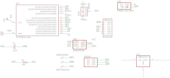
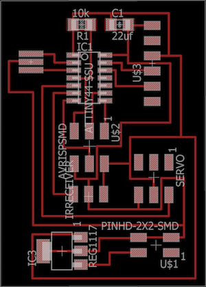
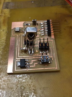
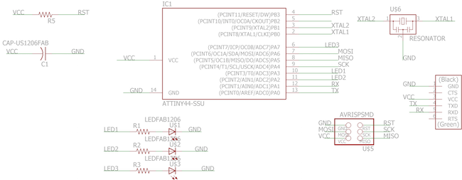
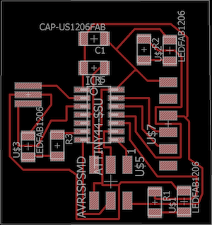
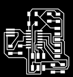
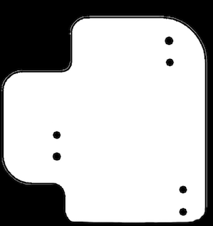
Alright, time for some electronics. Like everything else this time around, because it's the final project it must first go wrong at least 6 times before something goes right. This was no exception. I went into this with a lot of preparation and a lot of things that had worked separately in past weeks which helped for the start (also helped my anxiety). Basically, this board is meant to read the unique IR LED blink of each cat and either do nothing, open the bowl or close the bowl by using the servo as an output device. Using the hello world servo board from Neil's templates as an example, I designed this board with all the same components while adding a pin for the IR Receiver.
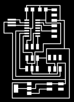
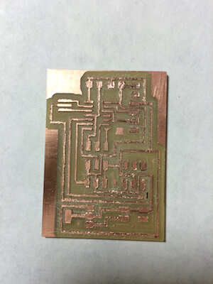
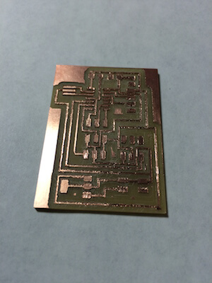
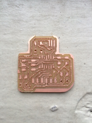
Post-design, the work flow to actually manufacture a board is getting easier each time, particularly the soldering. However, the mills turned out pretty badly on this board so I spent a lot of time deburring and trying to clean up the traces. Other than that this process was similar to every other electronics production week.
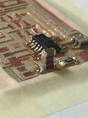
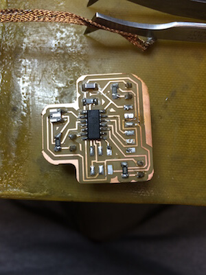
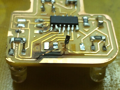
Once everything was ready to go, I wanted to try and augment my code by using attachinterrupt() from Arduino. Amanda, who is a saint, helped me work on this code using an Arduino, breadboard and oscilloscope to see what kinds of signals we were seeing. The way attachinterrupt() works is that it senses when the state of the LED pin changes. In the case of the IR Receiver, when it receives IR light it goes to 0 V whereas when it's listening its at 5V. By measuring the time it took between interrupts the pulse length of the LED could be detected, this also meant that I could code my LEDs in such a way that the time between pulses would be different enough for the code to be robust. The unfortunate thing about attachinterrupt() is that there's not a good way to use it with the Attiny44, I was very sad. But if were to use an Arduino or ATMega I think it would work. Maybe for future iterations. From there I decided to go back to the code I had used in the inputs week and tweak it so it could work. The new board I made was not reading the receiver in the same way, instead nothing was popping up on the serial monitor when usually values based on the blink frequency do. I wrote a line in the setup that would print 'finish setup' at the end of the setup loop, and it turns out that everytime the receiver was reading the LED it would print "finish setup". I checked everything with a multimeter and oscilloscope and couldn't figure out what was going wrong. I desoldered the ATTiny44 thinking maybe there was an issue with the reset pin. Turns out the trace for the IR receiver and the reset pin were in contact. As I was repairing my board, desoldering and resoldering my poor, sad traces that had been deburred too many times ripped off. :( I decided it might be best to try and attach a servo to an empty pin from my old IR receiver board and if I had time after debugging I'd remill a new board. I didn't have time...... Below is a picture of my old board, but you can also see it in action in Input Devices.
Just as a sanity check, I uploaded the code from input devices week and used my new LED boards to make sure the counters were set just right. I had to make one LED board blink once every second while the other blinks 10 times in a second. I set a threshold of 4 above which would be considered the good cat--green LED, and below which was a bad cat-- red LED. Sorry in advance about my face, the only camera to properly pick up IR LEDs is the selfie camera :P.
IR LED Receiver Code
////////////////////////////////////////////////
// HTM(A)A Final Project
// Camille Henrot
// IR RECEIVER
///////////////////////////////////////////////

// Software Serial Setup
#include <SoftwareSerial.h>
SoftwareSerial mySerial(0, 1); // RX, TX
// Define workspace
int counter=0;
int val ;
//int timer=1000;
unsigned long timer2 = millis();
unsigned long timer = millis();
void setup() {
  pinMode(2, OUTPUT);
  pinMode(3, OUTPUT);
  mySerial.begin(9600);
  mySerial.println("Finished Setup");
}

void loop() {
  if (mySerial.available()){
    val=mySerial.read();
  }
  unsigned long current_time2 = millis();
  if (digitalRead(A7) ==0){
      counter++;
      while (current_time2 - timer2 < 100){
        delay(1);
        current_time2 = millis();

      }
      //mySerial.println(counter);
      timer2 = current_time2;
  }

  // remeasure
 unsigned long current_time = millis();
  if (current_time-timer > 1000){

  if (counter>1 && counter< 4){
   val = 2;
   mySerial.print(val);
   digitalWrite(2, HIGH);
   delay(100);
   digitalWrite(2, LOW);
   //return;

  }
  else if (counter>4){
    val = 3;
    mySerial.print(val);
    digitalWrite(3, HIGH);
    delay(100);
    digitalWrite(3, LOW);
    //return;
  }
  else{

  }
        timer = current_time;
        counter=0;
  }


}
I had already played with a servo before but I wanted to find a simpler code that would just sweep the servo. After a few internet searches I found a tutorial about Arduino, servo sweeps and attiny44... HOW PERFECT. I put together some quick code with the servo pin that was empty on my inputs week board, and, incredible, it worked first try. That may be the first and last time that will ever happen.
Servo Sweep Round 1
///////////////////////////////////////
//HTM(a)A Final Project
//Camille Henrot
//SERVO SWEEP 1
//////////////////////////////////////

const byte servo  =    8;         // Servo pin on ATtiny
int tPulse        = 4000;         // Total pulse length on 1 Mhz clock
int hPulse        =   60;         // High pulse time (60=0deg -> 280=180deg)
bool Dir          =    1;         // Servo direction


void setup() {
  pinMode(servo, OUTPUT);
}

void loop() {
  digitalWrite(servo, HIGH);                // Set pin high to start pulse
  delayMicroseconds(hPulse);                // High pulse angle data
  digitalWrite(servo,LOW);                  // Set low for the rest of pulse
  delayMicroseconds(tPulse-hPulse);

 if (hPulse < 280 && Dir == 1) hPulse+=10; // Rotate servo to 180 degrees
 else if (hPulse >= 280 && Dir == 1){      // Servo hit upper limit
   hPulse = 280;                           // Keep servo angle in bounds
  Dir=!Dir;                               // Switch direction
 }
 if (hPulse > 60 && Dir == 0) hPulse-=10;  // Rotate servo to 0 degrees
  else if (hPulse <= 60 && Dir == 0){       // Servo hit lower limit
   hPulse = 60;                            // Keep servo angle in bounds
    Dir=!Dir;                               // switch direction
     digitalWrite(servo,LOW);
 }
  delayMicroseconds(500); // Give servo some time to move before giving it a new position
}
The next step, of course, was integration of both components. I thought this would be simple, I just had to add the servo movement code to the original IR receiver code. Boy, was I wrong. There were moments where the servo would nudge slightly. There were also moments where the servo would heat up ridiculously. I had a feeling it had to do with timing and the way the servo was being told to move in conjunction with a much faster response for the IR Receiver. Instead of being told to move a full 180 degrees, the servo would only move 10 degrees each time the IR Receiver read a value. After a little while of the servo heating up, I decided I needed to take a step back and reevaluate what I was doing.... also sleep, sleep was necessary.
I do want to thank Jonathan for being so patient and teaching me the true value of formating my code. Also for bringing a lot of clarity to how to debug code... which prior to this was mostly luck for me. For posterity, the code I was using my first go at integration is below.
System Integration Round 1
////////////////////////////////////////////////
// HTM(A)A Final Project Selective Cat Bowl
// Camille Henrot
// IR RECEIVER & SERVO INTEGRATION ROUND 1
///////////////////////////////////////////////

// Software Serial Setup
#include <SoftwareSerial.h>
SoftwareSerial mySerial(0, 1); // RX, TX
// Define workspace
int counter=0;
const byte servo = 8;
int tPulse = 4000;         // Total pulse length on 1 Mhz clock
int hPulse =   60;         // High pulse time (60=0deg -> 280=180deg)
bool Dir = 1;
bool shouldOpenCatFood = false;
bool didSeeBlink = false;

//int timer=1000;
unsigned long timeSinceCheckedCount = millis();
unsigned long timeSinceReadIR = millis();
int timeout_IR_LED = 100;   // rate at which we count
int timeout_SERVO = 2000;   // rate at which we respond to the count


void setup() {
  pinMode(2, OUTPUT);
  pinMode(3, OUTPUT);
  pinMode(servo, OUTPUT);
  mySerial.begin(9600);
}

void loop() {

  if (mySerial.available()){
    mySerial.print("counter: " + counter);
  }

  unsigned long current_time = millis();

  // check to see if we see a blinking light
  if (digitalRead(A7) == 0)
    didSeeBlink = true;

  // if it has been a while since we last read IR, do it
  if (current_time - timeSinceReadIR > timeout_IR_LED) {
    if (didSeeBlink){     // we saw a blinking light this period, so count up
      counter++;
    }
    didSeeBlink = false;            // reset the blink finder, so that it can go in search of another blink
    timeSinceReadIR = current_time; // reset our timer, so we only read every timeout_IR_LED milliseconds
  }

  // check our count values
  if (current_time - timeSinceCheckedCount > timeout_SERVO){

    // reset leds
    //digitalWrite(2, LOW);
    //digitalWrite(3, LOW);

    if (counter > 1 && counter <= 8){
      //digitalWrite(2, HIGH);
     mySerial.println("open");
      shouldOpenCatFood = true;
    }
    else if (counter > 8){
    //  digitalWrite(3, HIGH);
      mySerial.println("close");
      shouldOpenCatFood = false;
    }
    else {
     // shouldOpenCatFood = false;
      // we saw no blinks... cool, this is what will happen most of the time
      // unless your cat is garfield
    }

    timeSinceCheckedCount = current_time;
    counter = 0;  // reset our counter to count again for another timeout_SERVO milliseconds
  }

  if(shouldOpenCatFood)
    openCatFood();
  else
    closeCatFood();
}

void openCatFood() {
  // set servo to open state

  digitalWrite(servo, HIGH);                // Set pin high to start pulse
  delayMicroseconds(hPulse);                // High pulse angle data
  digitalWrite(servo,LOW);                  // Set low for the rest of pulse
  delayMicroseconds(tPulse-hPulse);

  if (hPulse < 280)
    hPulse += 10;                  // Rotate servo to 180 degrees
  else if (hPulse >= 280) {        // Servo hit upper limit
    hPulse = 280;                // Keep servo angle in bounds
  }
}

void closeCatFood() {
  // set servo to closed state
  digitalWrite(servo, HIGH);                // Set pin high to start pulse
  delayMicroseconds(hPulse);                // High pulse angle data
  digitalWrite(servo,LOW);                  // Set low for the rest of pulse
  delayMicroseconds(tPulse-hPulse);

  if (hPulse > 60)
    hPulse -= 10;                  // Rotate servo to 180 degrees
  else if (hPulse <= 60) {       // Servo hit upper limit
    hPulse = 60;                // Keep servo angle in bounds
  }

}
After talking to Dan the morning after the servo overload, he suggested I look into a different Servo library for the ATTiny44 and also that I add some capacitors to my old board just for good measure. I did this, I added 22microfarad in capacitance and downloaded a new library. The library I ended up finding was called Software Servo, and it allowed me to use the regular Arduino library commands to attach and control the position of the servo. Below are some videos and the code when I was playing with just the servo.
////////////////////////////////////////////////
// HTM(A)A Final Project Selective Cat Bowl
// Camille Henrot
// SERVO ROUND 2
///////////////////////////////////////////////


#include <SoftwareServo.h>

SoftwareServo myservo;                 // create servo object to control a servo
                                       // a maximum of eight servo objects can be created

int pos = 179;                           // variable to store the servo position

void setup()
{
  myservo.attach(8);                  // attaches the servo on PB1 to the servo object
}

void loop()
{ //pos=179;

  for(pos = 0; pos < 180; pos += 1)  // goes from 0 degrees to 180 degrees
  {                                  // in steps of 1 degree
    myservo.write(pos);              // tell servo to go to position in variable 'pos'
    SoftwareServo::refresh();        // must call at least once every 50ms or so to keep your servos updating
    delay(15);                       // waits 15ms for the servo to reach the position
  }
  for(pos = 180; pos>=1; pos-=1)     // goes from 180 degrees to 0 degrees
  {
    myservo.write(pos);              // tell servo to go to position in variable 'pos'
    SoftwareServo::refresh();
    delay(15);                       // waits 15ms for the servo to reach the position
  }
}
Again came the time to try integration. This went a lot faster than I had anticipated. The videos below show the behavior that warranted the one slight change in code I needed to make. Basically everytime the servo hit a position it would continue to nudge to that position so long as the IR receiver was still telling it to move. Instead I changed the code such that it would stay at the same position without nudging. Furthermore, the final code includes the addition that the general state of the bowl is closed. I.e. if there is no cat it closes. Or if Evie leaves her food bowl for too long it will close
System Integration Final Code
////////////////////////////////////////////////
// HTM(A)A Final Project
// Camille Henrot
// FINAL CODE- IR RECEIVER & SERVO
///////////////////////////////////////////////

// Software Serial Setup
//#include <SoftwareSerial.h>
//SoftwareSerial mySerial(0, 1); // RX, TX

#include <SoftwareServo.h>
SoftwareServo myservo;

// Define workspace
int pos = 0;
int counter=0;
int val ;
//int timer=1000;
unsigned long timer2 = millis();
unsigned long timer = millis();


void setup() {
  pinMode(2, OUTPUT);
  pinMode(3, OUTPUT);
  myservo.attach(8);
  //mySerial.begin(9600);
  myservo.write(pos);
}

void loop() {
  /*if (mySerial.available()){    val=mySerial.read();  }*/
  unsigned long current_time2 = millis();
  if (digitalRead(A7) ==0){
      counter++;
      while (current_time2 - timer2 < 100){
        delay(1);
        current_time2 = millis();

      }
      //mySerial.println(counter);
      timer2 = current_time2;
  }

  // remeasure
 unsigned long current_time = millis();
  if (current_time-timer > 1000){

  if (counter>1 && counter< 4){
   val = 2;
   //mySerial.print(val);
   digitalWrite(2, HIGH);
   delay(100);
   digitalWrite(2, LOW);
   if (pos != 0){
   for (pos = 180; pos > 0; pos-=10){
      myservo.write(pos);
      SoftwareServo::refresh();
      delay(15);
    }
   }
  }
  else if (counter>4){
    val = 3;
    //mySerial.print(val);
    digitalWrite(3, HIGH);
    delay(100);
    digitalWrite(3, LOW);
    if (pos != 180){
    for (pos = 0; pos< 180; pos+=10){
    myservo.write(pos);
    SoftwareServo::refresh();
    delay(15);
   }
    }
  }
  else{
    if (pos != 0){
   for (pos = 180; pos > 0; pos-=10){
      myservo.write(pos);
      SoftwareServo::refresh();
      delay(15);
    }
    }
  }
        timer = current_time;
        counter=0;
  }
}
IR LED Cat Collar
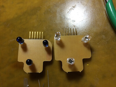
Originally, I was simply going to have only one cat wearing an IR LED collar, the IR Receiver would detect light and would open for a certain amount of time then close. This wouldn't have required any code or a microcontroller, just batteries, LEDs and resistors. But I realized, Rupert is a bit more devious than I give him credit for. He would very easily pounce behind Evie and eat all her food. So I decided to make two separate LED boards each with microcontrollers to control the blink frequency of each individual cat. As I noticed in inputs week one IR LED would not suffice. So I designed a board with three IR LEDs that would allow for higher power and increase the probability of being read by the IR Receiver.
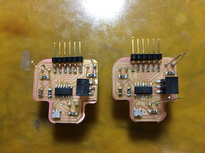
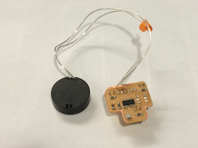
The idea was to use an external power source that used two 3V batteries. I found some nice battery cases on amazon for $1.50 that would hold it and conveniently looked like something that could be put on a collar. To do this, I wanted to program the LEDs until they worked, then desolder the FTDI header and the ISP header. This way I could lay the component side flat on the battery case and the LEDs would face outward. I must admit I never got a chance to make a good casing for both the battery case and the LEDs, but if I had more time I would 3D print a quick snap fit cover that would hold the board in place. This process went well for the first LED board. Unfortunately, the desoldering on the second board tore up some traces. I was able to temporarily patch it just to make sure all electronics worked, but soon thereafter traces were disconnected. I remilled this LED board and was much more careful with the desoldering process the second time.
IR LED Blinking
Didn't I tell you I was a master of blinking LEDs? ;)
//////////////////////////////////////
//HTM(A)A Final Project
//Camille Henrot
//IR LEDs
/////////////////////////////////////

int led1=3; //Define LED pins
int led2=7;
int led3=2;

void setup() {
  pinMode(led1, OUTPUT);
  pinMode(led2, OUTPUT);
  pinMode(led3, OUTPUT);


}

void loop() {
  digitalWrite(led1,HIGH); //Three LEDs on each board
  digitalWrite(led2,HIGH);
  digitalWrite(led3,HIGH);
  delay(20);               //Fast blink for opening the bowl
//delay(100);              //Slow blink for closing the bowl
  digitalWrite(led1,LOW);
  digitalWrite(led2,LOW);
  digitalWrite(led3,LOW);
  delay(20);
//delay(900);

}
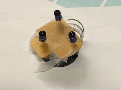
The other issue about this currently is that it's a little big. Rupert was not happy when I put this on his collar, so a great next iteration would be to make that package even smaller and lighter to make it almost like a regular collar tag. This could be done with some surface mount IR LEDs as well as maybe only relying on 3V power for a smaller battery pack. I could even go so far as making a flexible circuit using copper and the vinyl cutter to mount the components directly on the battery pack! Ahh the possibilities. I did play with cutting copper to help Liz Schell out with her final project, we found the cutting force of 70g and a speed of 1cm/s worked this time around.
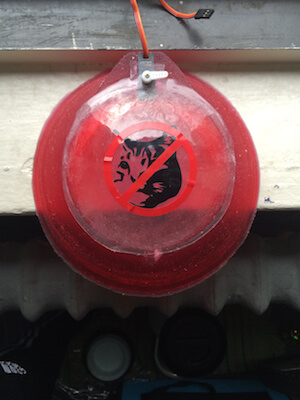
Vinyl Cutting
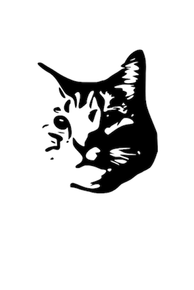
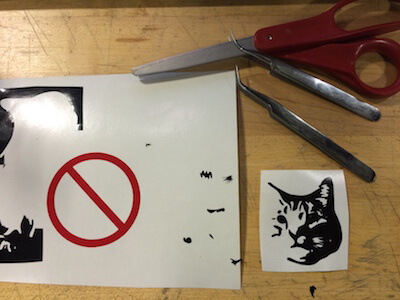
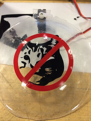
As a break from all the other intense fabrication I took a few minutes to go back to my roots and use the first machine I ever used in this class-- The vinyl cutter. Ah it's simplicity has never been more perfect to me than in this moment. Of course, I made another sticker of Rupert, smaller this time. On top of it I made a stop sign sticker. Together they would become an infographic for my entire project. I think it gives it a nice touch. The settings for cutting vinyl are pretty consistent 160g force with a 20cm/s speed. In no time at all it was done.

System Integration
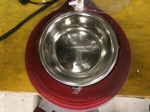
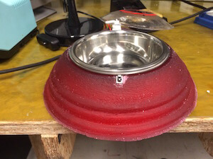
And now what we've all been waiting for... THE FINAL PRODUCT WOOOOO! I first wanted to try to use the inner bowl that I cast but it's pretty ugly... :(
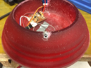
So instead I went to Petco and grabbed a "bowlmate", these are great little stainless steel bowls that are easy to clean and come in a bunch of different sizes. It was $3.99 to buy, so not a huge investment, cheaper, in fact, than the oomoo, though I really wish I had made that work. Ahhhh the tragedy of time constraints.
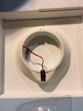
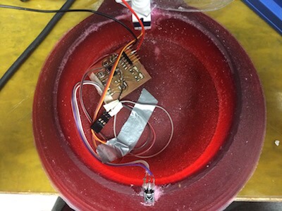
Next, I needed to put my electronics in. These hide underneath the inner bowl. Due to geometry of the design, namely needing the IR Receiver in the front and the servo in the back, I had to run wires from my board to each location to connect. Neil came in as I was doing this and told me to be very careful as that is often where failures occur. After being very careful, as instructed, and using a bit of duct tape for good measure I figured due to the time constraint (it was 4pm day before) that this would have to do. It does the trick. Though if I were to redesign the board, I would do so such that I could have female FTDI plugs for the relevant components so it wasn't so dependent on small solder joints and wires hopefully not touching each other. I hot glued the IR receiver into the slot that was designed for it's placement in the mold, and after filing the servo shelf a little (I ended up using a slightly bigger servo then originally planned) the servo fit snugly in the bowl. Lastly, I put the lid on the servo head and screwed it in place. I used a little glue as well so that the lid couldn't rotate freely without servo movement. I had drilled the hole a little big. Ideally, I would have 3D printed a joint for the lid that would have the teeth, much like the attachments the servo comes with, for a better fit.
 AND IT WORKS!
NOTE: This video was taken before I glued the dome lid to the servo, which is why it slips and overshoots the top of the bowl.
Rupert's First Reaction-Intrigued yet unimpressed...TypicalAs mentioned before, neither Evie nor Rupert were in the mood to get their collars tampered with so I was unable to get a full action video. However, I did want to see, given there was food in the bowl, if a closing bowl would scare Rupert. It didn't, he's fearless. That means I've at least outdone some of the other selective cat bowls on the market as it doesn't scare cats. SUCCESS
MORE VIDEOS OF RUPERT BECAUSE HE'S GREATFuture Work
I'm enormously proud of this project, but of course, there is room for improvement and iteration which I hope to be able to accomplish, one day, in the future... I need a break from this electronics lab first.
I'd like to get a better surface finish on the outer bowl, this would require a mold with better surface finish in ideally a nicer material such as wax, or potentially a better post-processing method on the foam, heat may work. This would of course mean more time and more money to buy the stock and produce. While oomoo is nice, I'd like to find a better flexible molding material that isn't as expensive to be able to make my molds out of. For the inner bowl, I would have to redesign the mold such that it's parting line was at the top rather than the bottom, more clamping would also help to avoid leakage of material. The dome lid needs some work in terms of it's joint and it's shape, these would help to ensure that Rupert can't paw or nose his way into the bowl.
From an electronics perspective, I think what would be great would be to have IR Receivers around the perimeter of the bowl. Turns out that only having one at the front might make for a sad hungry cat. Furthermore, I'd like to add an additional output device, mostly a speaker to give feedback to Rupert, preferably it would be my voice saying "No Rupert!", this way he would learn that the bowl was not for him. I'd also like to minimize the size of the collar attachments as cats are pretty quick to dislike something forever, fickle beasts.
In all, I think I did a great job putting together a project that integrates the new skills I learned this semester in one, fairly useful, and functional system!! CELEBRATION :D
I'd like to thank the following people:
Neil- For teaching the most challenging class I've ever taken at MIT Nadya- For your support from the beginning right to the very end Calvin, Liz & Nico- My partners in crime And of course the brilliant TAs and Shop staff Tom, John, Amanda, Dan, Jonathan-- Your help made this all possible