Electronics Production
FabISP In-System Programmer
We learn the tools and processes to fabricate the predesigned in-system programmer (ISP) (sometimes in-circuit programmer), which is an embedded device with a microcontroller (MCU) that can be (re)programmed after assembly. It’s used to program our custom logic on other circuits. The MCU costs ~$1 (we use the ATTiny44a) and the entire board ~$5 in parts.
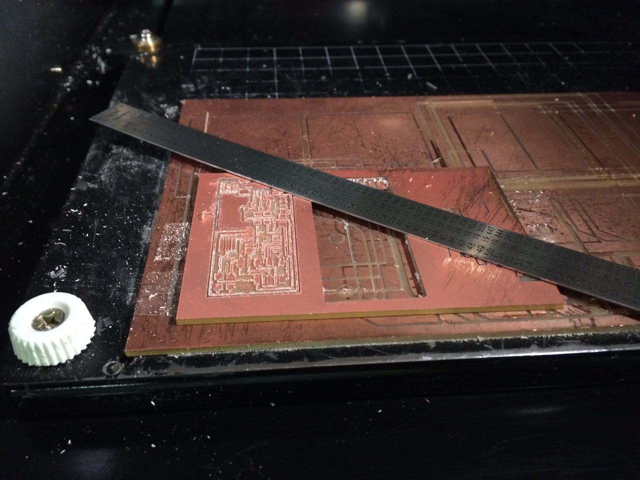
PCB Milling
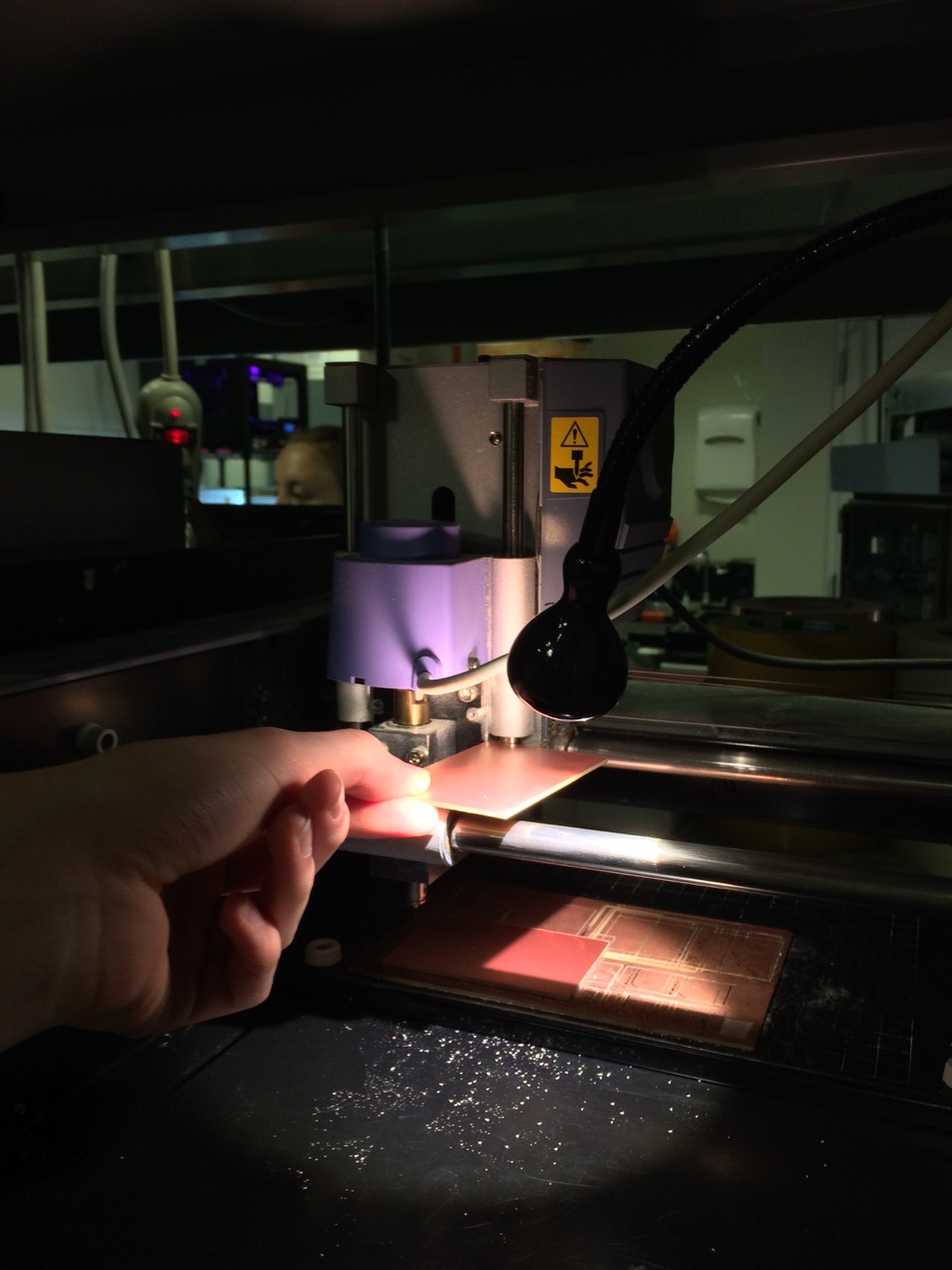
We use the Roland Modela MDX-20 precision mill hooked to a workstation (Linux: fab/fab). The CBA tutorial page and the video walkthrough on YouTube by Charles are useful for a general overview, especially for machine/tool setup, but have varying stages of obsoleteness as they don’t use the current fabmodules.org.
- The standard board stock we use is 2×3in and consists of epoxy as substrate with a copper layer (“FR1”). Never machine “FR4” stock because it has glass in it, which splitters and destroys the tool. By request, there’s also some double-sided and 4×6in stock in the inventory.
- Use a generous amount of double stick tape (make sure the tape doesn’t overlap, to keep the stock level) to hold the board stock from below because a vise would bend it, which is bad for milling. If the sacrificial layer looks ugly, clean it with rubbing alcohol (ethanol, isopropanol, etc.) or even replace it, to achieve a good board adhesion.
- Power on the Modela, if any LEDs are blinking, press and hold the buttons UP and DOWN at the same time to cancel the current job.
- Launch StartModuleServer from the desktop icon and open fabmodules.org in the browser: input format > load settings > LOAD_THESE_SETTINGS (these are the site settings and should be on the desktop)
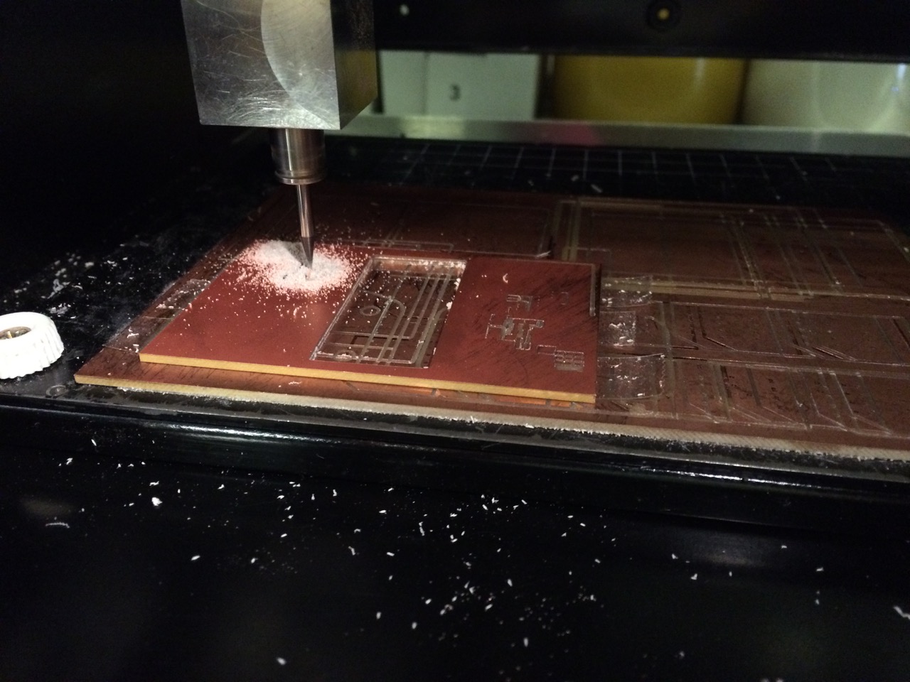
- Load B/W PNG (black gets cut) and choose output: (1) traces with a 1/64in end mill, (2) outline with a 1/32in end mill (cut in multiple passes).
- Sometimes cut depth needs to be increased a bit, e.g. from 0.1 to 0.12. However, too deep of a cut causes fine traces to easily get ripped off and decreasing e.g. to 0.08 might help in this case. The goal is to cut just enough copper that the epoxy substrate shows.
- 1/64in end mills (= ~15mils = 0.4mm) are good for as small as 0.8mm (in-between pads) pitch components. Only for components with as tiny as a 0.5mm pitch we need to go down to mill that specific area with a 1/100in (10mils) end mill.
- Images exported from EAGLE should have 600DPI. Neil’s examples have 1270DPI – leave this as is in fabmodules because changing to 600DPI will mill a blown up version.
- Press the VIEW button on the Modela so the LED is not lit and load the tool. (At any point in the process, this button acts like a pause/resume button.)
- Zero X and Y manually from fabmodules.org. Think about where the outline will go and position it efficiently on the board stock to be resourceful. X and Y need to remain the same for traces and outline!
- Zero Z by adjusting TOOL UP/DOWN buttons (tool will rotate), loosen both set screws and gently drop tool all the way onto board, and finally hand-tighten both screws again. To reduce runout we want to have only a short piece of shank from the end mill sticking out. So the spindle should be far down but not too far because otherwise there would be no room for the tool to jog. To cut through, the gap of spindle travel needs to be at least the thickness of stock.
- For better results, lower the speed to 3 for the traces, especially for very new (grab) or old (push) end mills. To be resourceful about time and tools, we don’t need to remove all copper (default number of offsets is 4). Remove it all if you do high-frequency electronics or if you want a clean board. Further, one can increase the offset overlap to e.g. ~75% to only move by 25% of the tool diameter in-between offsets (this is inverse from the notion other software uses).
- To get a really clean board yet be resourceful, a good strategy might be to only do 2 offsets with the 1/64in end mill and then clean up all remaining copper with the 1/32in end mill before doing the cutout.
- If the fabmodules.org preview shows some distinct traces as connected blob, “lie” about the toolsize and decrease its size until we get the intended path in-between the blob (e.g. to 0.38). Some people always decrease a bit because 1/64in is actually less than 0.4mm (e.g. to 0.3969).
- Adjust the zjog to 0 if the head is going all the way up between cuts. If a zjog of 0 leads to scratches on the traces, set it to something small (maybe 0.05). Otherwise leave it at the default (usually 2).
- If a board has a lot of burr, it’s often due to vibration. Clean the bed and machine, re-align and hand-tighten screws of bed, renew sacrificial layer, check that the set screws aren’t stripped and hand-tighten them. Sometimes even the spindle has to be replaced.
- When using the Roland Modela SRM-20 precision mill in the machine shop, the z0 must be set to a value greater than the cut depth, otherwise the mill will continuously jog all the way up to zhome and down again. So “zero” the end mill when the toolhead is at e.g. z0=3mm. Also, every time after sending a command, before opening the lid, wait for a few seconds so the machine doesn’t go into the blocked flashing mode. Also ensure
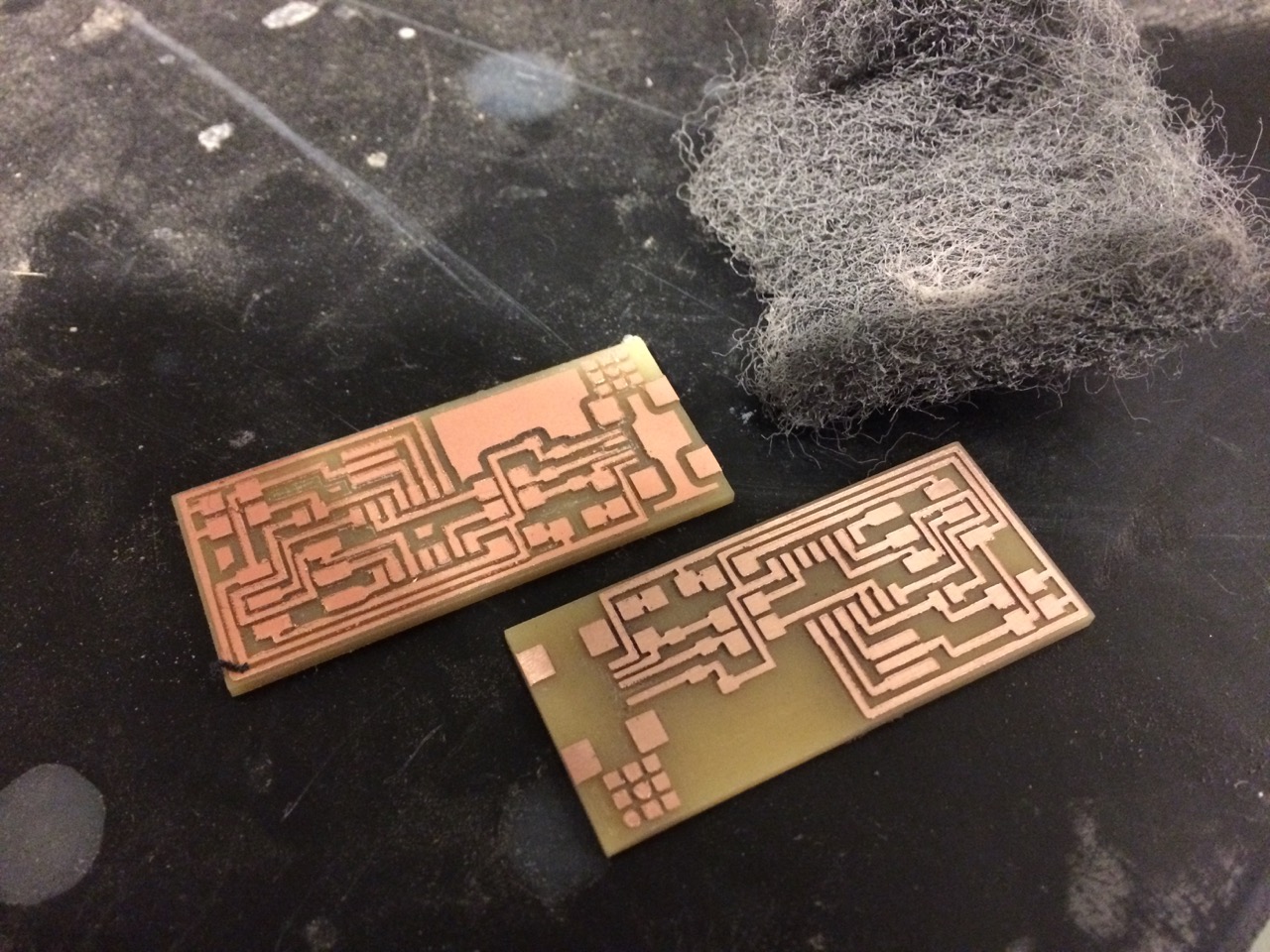
# chmod 777 /dev/usb/lp0. - Clean first with a vacuum cleaner. While still mounted, deburr with the edge of a tool such as a metal ruler and steel wool. After taking it out, clean it with soap and water. Finally, clean the traces with rubbing alcohol before soldering.
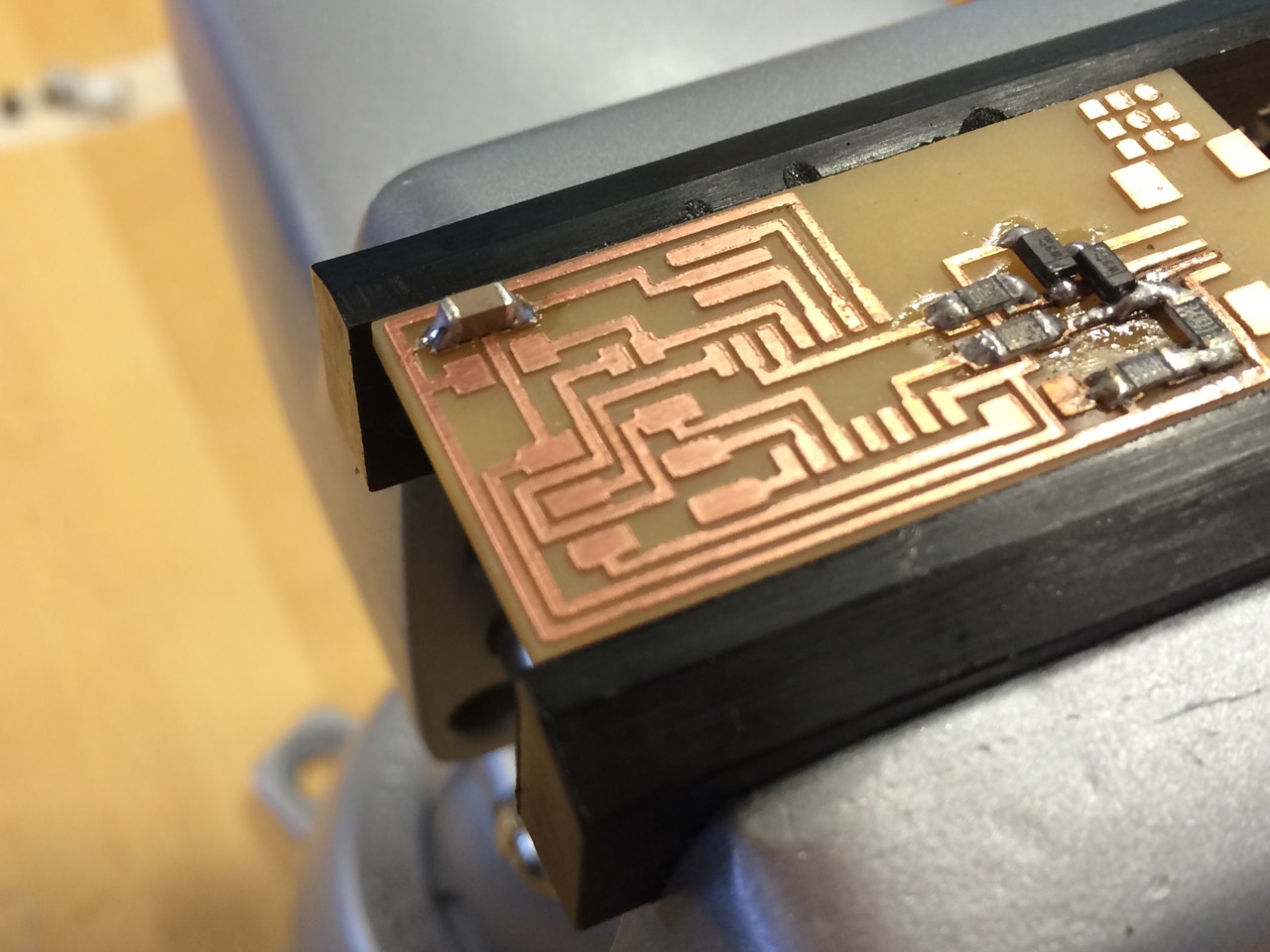
SMD Soldering
Thru-hole parts are mostly obsolete in mass production, hence we prefer to prototype with SMDs to avoid that time consuming translation. Once you master the SMD solder technique (drag soldering, surface tension), prototyping becomes quite quick. This YouTube video demonstrates impressively how precise soldering is all about getting the technique, temperature, and chemicals right. Note that the fumes are a nuisance if not inhaled all day but not a hazard.
- Stuffing order: from the inside of the board to the outside, and from the bottom (shorter components) to the top (taller ones)
- Chips have a dot on pin #1 and on the board the pad has a bump. For diodes, current flows in alphabetical order, Anode → Cathode. The tiny bar mark on the component package indicates the barrier of the electronic symbol (i.e. on the Cathode side).
- Soldering iron needs to be shiny. Clean it with brass wool or sponge. When heating it up, put solder on it. From this YouTube video I gathered that a good temperature is 610℉ (~320℃); Will Langford suggests 750℉ (~400℃).
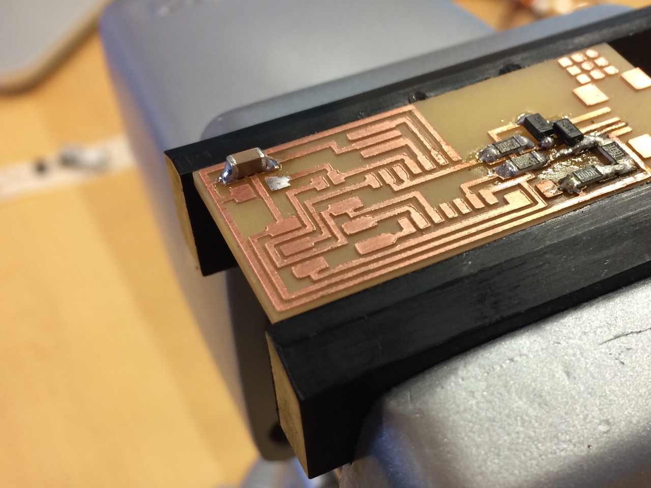
- Tinn the pad i.e. put a small bump of solder on it
- Bring in component with tweezers and reheat to "glue" it in place
- Solder opposite joint by heating pad and component simultaneously with iron tip, then probe with solder until it nicely flows and remove iron after ca. 1 sec. (longer burns all the flux and the joint will be matt)
- To solder very close pins like the mini USB port, oversolder and then use braid to remove the solder bridges.
- When desoldering using braid, counterintuitively you need to put solder onto the braid first to transfer heat. When using a heat gun, hold part you don't want with tweezers and let the board fall.
- Finally, clean the board with rubbing alcohol.
Programming
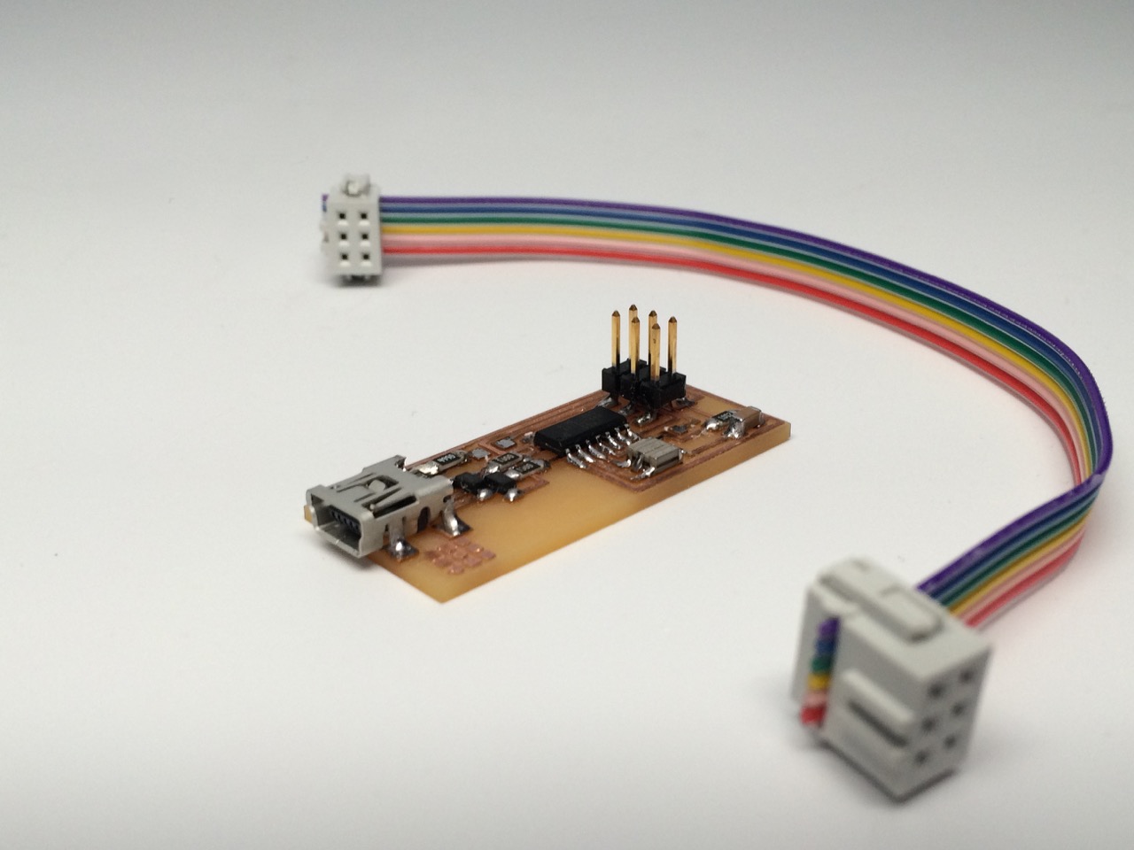
We use the Atmel AVRISP (blue box) to program our board. Once our board is programmed, we can desolder the two bridges SJ1 and SJ2 (0-Ohm resistors) and itʼs basically a replacement for that programmer. I also made an IDC ISP cable, ensuring to connect header pin 1 to pin 1.
- Connect USB and power
- $ make clean
- $ make hex
- % make fuse (check programmer in Makefile, may need to repeat)
- % make program (rc=-1 error is OK, as long as it detects USB device)
More information on how to program embedded chips and setup the development environment on macOS (FTDI driver, CrossPack for AVR Development, etc.) can be found on the week 8 Embedded Programming page.
Outlook
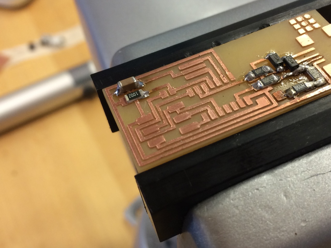
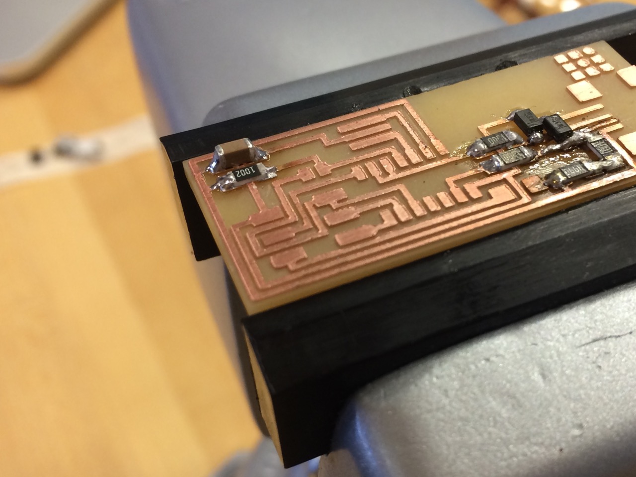
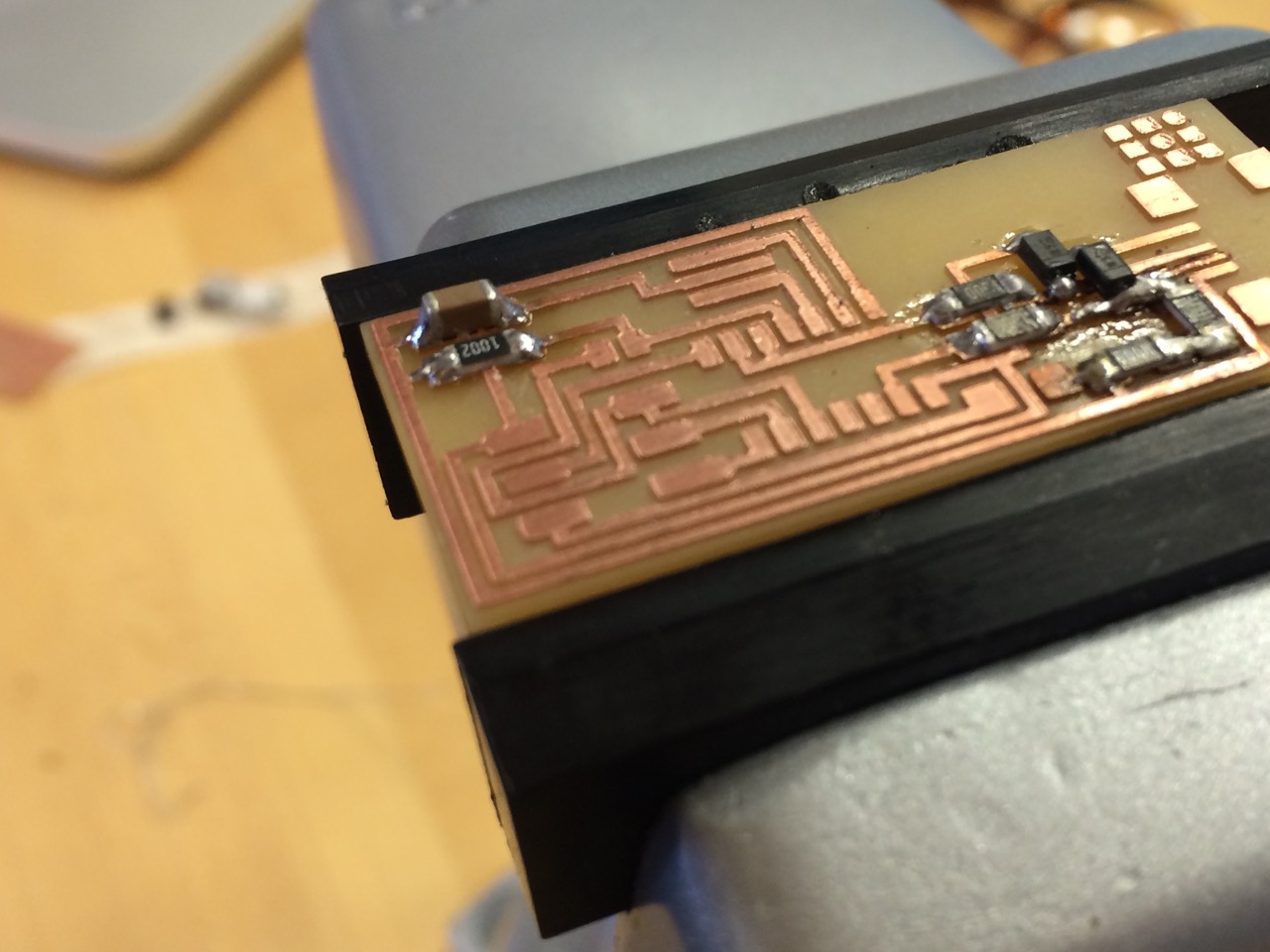
An interesting aspect of milling PCBs is that the outline doesn't need to be rectangular.
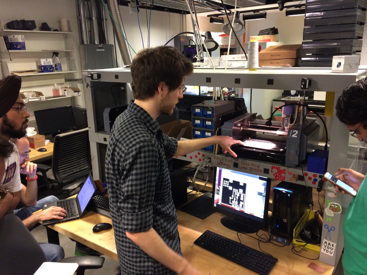
I’d like to explore how to make flexible circuits using the vinyl cutter and thin copper sheets (CBA Tutorial, Do’s and Don’t of Vinyl Cutting a Circuit). The circuit is more fragile and the traces width need to be increased but it can mounted on almost anything and looks beautiful. Nadya Peek wrote an instructables.com tutorial on it and there’s a beautiful kokobant.at tutorial on fabric PCBs. Another cool thing is conductive silver ink from a ballpoint pen, e.g. Circuit Scribe by Electroninks (I purchased the Circuit Scribe Lite Kit).
Eric VanWyk has experience with laser “cutting” PCBs and there’s a FabAcademy.org tutorial.