I wasn't able to finish soldering my board two weeks ago, so I did it this week on top of programming. I learned about electronic design and troubleshooting.
Here was my initial workflow:
-Design board in Eagle
-Export eagle file as a monochrome .png file
-Calculate path on Fab Modules
-Sent job to the mill
-Solder elements on board
-Load bootloader
-Program your board!
Here is my updated workflow:
-Design board in Eagle
-Check for errors!
-Export eagle file as a monochrome .png file
-Check for errors!
-Calculate path on Fab Modules
-Check for errors!
-Sent job to the mill
-Check for errors!
-Solder elements on board
-Check for errors!
-Load bootloader
-Check for errors!
-Program your board!
-Check for errors!
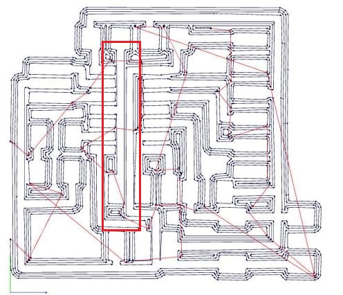
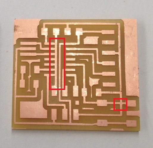
Because I missed checking for errors at every step, I increased my work time by many many hours. For example, I didn’t study the path that Fab Modules calculated before sending my job to the mill. I didn’t realize that some of my paths were not separated, and that some were poorly laid. I designed, milled and soldered my board (this took hours!)before this issue came to light. Actually, it came to light as I was trying to burn the bootloader, which was many many steps ahead of milling.
To correct for this, I narrowed the traces in Eagle by doing:
Change>Width>0.12
This didn’t help very much. I still had overlaps.
So I rearranged the traces in Eagle on top of narrowing them. This seemed to create other overlaps, however.
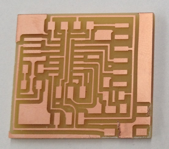
Finally, I narrowed traces, rearranged elements, and hacked fabmodules all at once. I used a tool diameter of 0.3 (in lieu of the default 0.4 tool diameter for a 1/8 inch bit) in Fab Modules to obtain thinner traces.
This worked finally to give a board that functioned well. This worked!
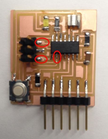
Finally, I had a few soldering errors where certain elements were hanging over the board rather than touching it.I had to correct for these as well to get my board to work
Programming the Board
I used the Arduino IDE to program my board through my FabISP. Here are the steps I took to set this up:
- Download and install Arduino.
- In Arduino, install support for the Attiny44.
I followed this tutorial from the High Low Tech group. This step is easy to do in more recent versions of Arduino, as they come with a built-in boards manager.
- Downloaded USBtinyISP (the FabISP is a USBtiny ISP) driver.
I downloaded the driver here from AdaFruit.
-Finally, I plugged in the FabISP and update its drivers.
I followed instructions on this page.
The process was simple: I went to the device manager on my computer and found the FabISP.
I right-clicked on the device and selected "Update Drivers". I navigated to the downloaded USBtinyISP driver folder and selected it.
This worked! My computer is now able to communicate with my FabISP.
What I made
My goal for this week was simple: Make the LED light up as long as the button is pushed and stop when the button is released and I was able to do this.
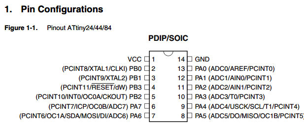
Below is the code that I used. I had the button on pin 3 of the Attiny44 and the LED on pin 7.