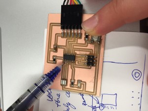
Week 5: Electronics Design
An EAGLE presses a button and turns on a light
Fall 2015
A few weeks ago, we made a Fab-ISP in-circuit microcontroller starting with a trace and a circuit design made for us.
The task this week was to do all of that ourselves: make that kind of design from scratch plus mill the board, solder it, and put on a button and an LED. Class notes here.
We started with a review of the CAD software we'd be using. I chose EAGLE -- an oldie but a goodie, as my camp counselor used to say about one of the more arthritic and nasty school horses. Thankfully, this software doesn't start eating grass randomly, but it does have its senior moments. If an old horse doesn't provide quite the metaphor you need, try imagining ClarisDraw but for designing a circuit. Oh, ClarisDraw was before your time? ...Exactly.
Beyond clicking icons and making pictures, what is actually going on in the circuit (i.e., what is the physics of it)? At a high level, Ohm's law and Kirchhoff's laws come into play. For that, my friend, I refer you to some terrific sources.
...ELECTRONICS!
Higher nerdiness/fondness for math background assumed (they came from an MIT Intro to EECS class):
Slides with a general introduction to electric circuits Constraint systems and circuits Circuit abstraction, modeling, and op-amps (Neil mentioned that we don't necessarily need to know about op-amps to do our assignment, but it's there if you need it, and the rest of the slides are still probably relevant)If you're looking for something that assumes less background/prior experience, these pages might help Basic electronics text Additional good electronics source Even more! (AND FRANKLY, BETTER THAN WHAT'S ABOVE)
Our heroic TFs put together a terrific Electronics tutorial + an Eagle tutorial you can check out here. It's got a link to Sparkfun’s electronics fundamentals, too.
OK, onto what I actually did.
After searching around a bit, I found this tutorial from an unknown benefactor at Fabacademy. That gave me a sanity check as I designed as to whether what I was making had any hope of actually working:
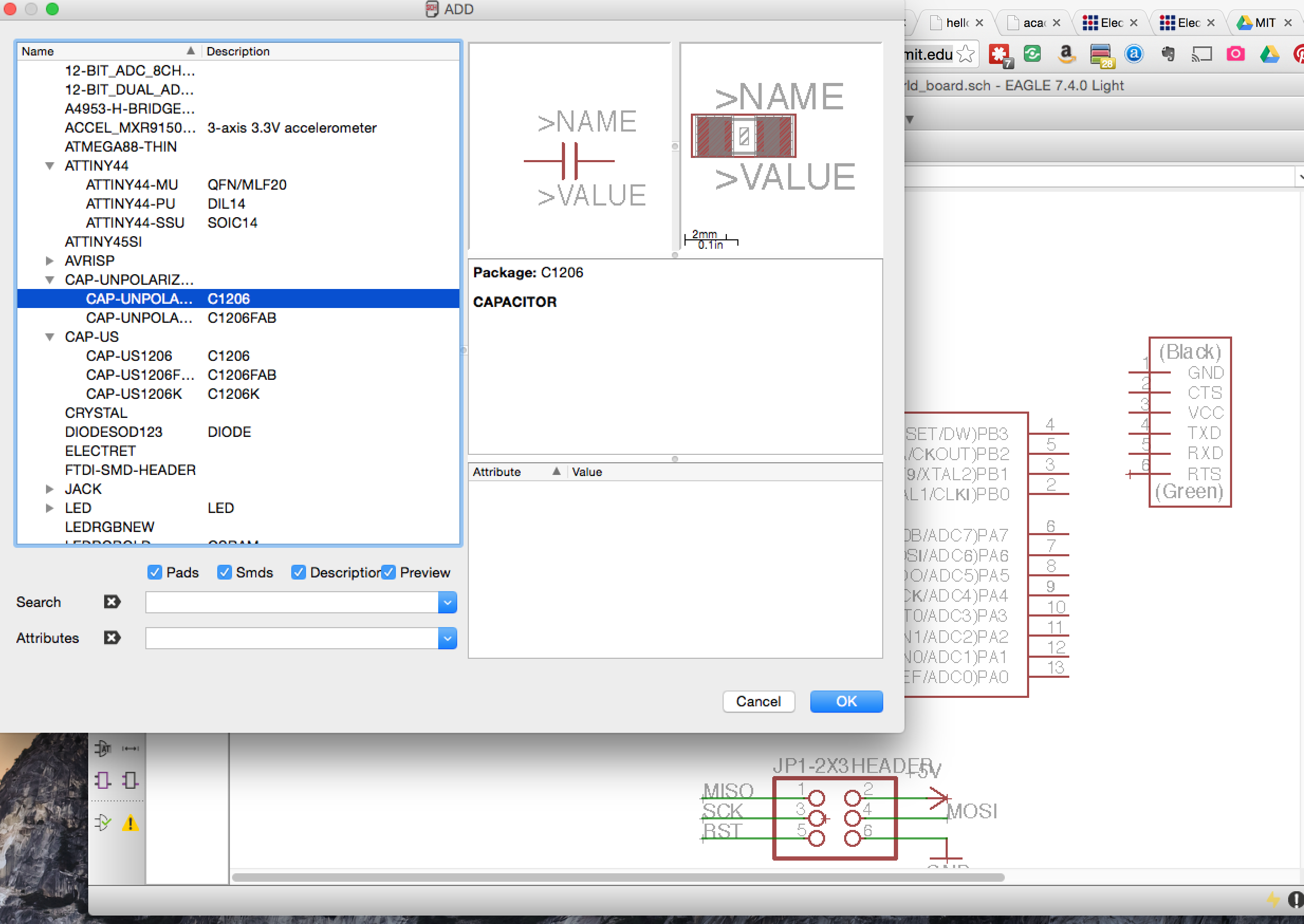
This is how you select parts in Eagle to put into your design. UIs like this are what remind me of that "oldie but goodie" school horse from camp. Check out the infinitely long, alphabetized list. Search? Barely heard of it. There is a search function, but it's mostly for show. Good times.
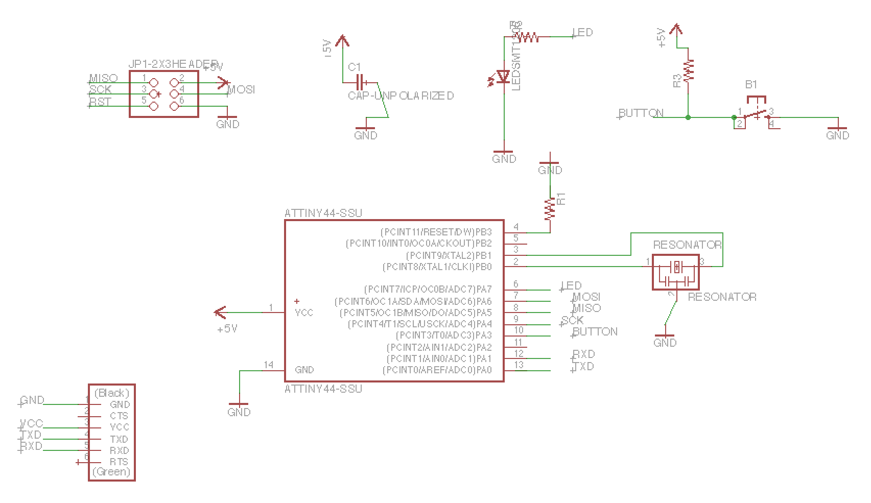
Anyway, here's the resulting schematic
Below, you can see the many errors listed in my Ratsnest window (red warning icons, etc). I didn't address all of these bugs, but I did pray. I thought maybe a higher power would make it just work out, no matter what. See, religion and science do go together.

This is a comparison between what I was trying to do and what the real thing should have looked like (ignore the color contrast, that's just a style choice). Mine is on the left, the original is on the right.
comparing what i did to what fabacademy did
Here's my resulting board. You can see that I incorrectly lost the R1 connections from the previous image, but I gained a few elsewhere:
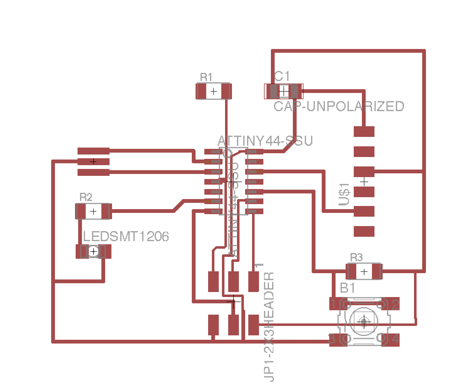
At 4:45am, I lost my resolve and decided to sleep. I know, I know, weak sauce.
So, my next steps will be getting those last few connections in, milling my shiny new PCB design using the Roland mill, and then soldering all the components on with my soldering skills that I won the hard way from my electronics production project a few weeks back.
**Second round! Renewed vigor! Second chances!**
Finishing up the electronics design and new LED and button-clad microcontroller board
The assignment itself involves using the FabISP programmer and the electronics design assignment. Because I had a backlog of unfinished aspects of both of those assignments, I struggled to get those done as well as get the new software done for this week. Details below.
PREFACE: Failing (relatively?) fast
Unlike some of my previous posts, this first section of the post is not going to detail a cheerful list of what worked. Because, well, mostly things just didn't work this week. To date, I've been fairly careful and/or lucky - I haven't run into too many bugs and I've mostly avoided damaging any of the multi-thousand dollar machines. All that changed this week.
"a stitch in time saves nine": The last time I put a thread through a needle was when, in kindergarten, I was assigned to make a penguin cushion. Mine ended up looking like a black and white pin needle cushion with terrified googly eyes appearing at Picasso-like angles. So, maybe if I'd learned the wisdom of this phrase at age five, I wouldn't have flopped so hard this week. Apparently, "a stitch in time saves nine" holds true not only in sewing but also in electronics. In the course of a few days and 10+ hours, I managed to:
Zero the Roland mill incorrectly and nearly drill through the sacrificial layer Render the Roland mill drill head incapable of working for a night Spend hours re-learning key features in Illustrator and Eagle that I had forgotten Create shorts in a board that had no shorts, in the very process of checking for shorts Major mistakes so far
Zeroing the Roland mill incorrectly and nearly drill through the sacrificial layer Render the Roland mill drill head incapable of working for a night Spend hours re-learning key features in Illustrator and Eagle that I had forgotten Issues with the Roland mill:
These are excerpted emails documenting the travails of the Roland mill...
Me at 11:13pm: "I put down a sign on the Roland mill saying not to use it. Here's what happened: there was one screw that seemed to have been pushed too far into the bit. We took it out, but it's possible that it abraded the inside of the head on its way out. Currently, there is resistance if you press the drill up into the head in preparation to zero your board, so I'm worried that when the machine runs, the bit won't be secured properly. Also, proper zero-ing is not really feasible. I'm not completely sure what caused it, but I'm guessing that I tightened the screws too much. A few of us tried diagnosing it but realized that our lack of experience could potentially do real harm, so we just left it alone. The 1/64 bit and the two screws are now inside the clear plastic box that says "1.5 mm hex key Spare Modela set screws. m3" right next to the mill. Very sorry to have caused and/or contributed to this problem!"
Rob at 9:42am: "The Roland is back in operation. Thanks, Elizabeth, for your diagnosis and communication. There was a metal burr in the collet which was impeding insertion of the tool - I reamed it out, and now the bit inserts smoothly. The threads are damaged, but it should still function well. When the threads give way completely, there is a spare spindle in the leftmost blue cabinet."
Phew!
Ok, major wins so far:
Basing my designs on the EAGLE schematics here, I did the following. The trace and outline designs came out, in the end: major issues here were re-drawing certain wires in Eagle that were unlikely to mill properly because they were too close to each other.

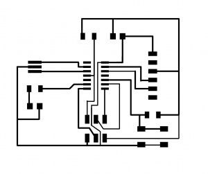
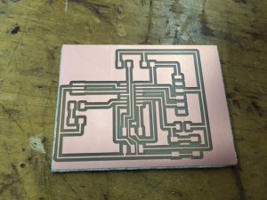
Next up, I had to solder the components onto this board and then test it. Configuration orientation: ground must connect to ground (black wire on FAB ISP to USB wire to the correct pin on the 6x1 header. You figure that out by visually tracing back from ground to the pins in the EAGLE schematic. Also, make sure that the rainbow cables have ground pin on the programming board going to ground on the new board to be programmed. In my case, that meant matching the blue wire to ground on each of the 2x3 headers. You can also check by looking in the data sheet (search for "ground"; it only shows up 8 times in the whole 286 page document, so you'll find what you're looking for pretty quickly; I looked at the schematic on page 2.)

