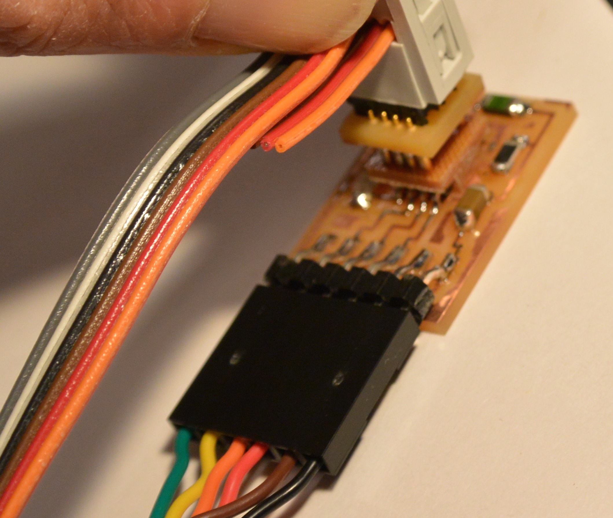
Connector using "pogo" pins to contact legs of tiny45 (and tiny44 in modified design) so that ISP 2x3 header is not required.

In the photograph above, note that there is no ISP header on the board!
First iteration, in which premade four-pin headers are used for the pin contacts, and ribbon cable wires are soldered individually into holes in an upper circuit board. This design works well, but presents many problems in contruction, since ribbon wires are difficult to solder onto the board.
Push-pin programmer for tiny45, made with individual pogo pins. One reason to use individual pins rather than multi-pin headers is that the design can be directly modified for tiny44 (or tiny10) without adding more than the one pogo-pin to the inventory. The top board is a standard one-sided milled PCB. The bottom is double the thickness, and can be milled on the circuitbaoard mill. I've defined its dimensions in an Eagle file as well as the top board.
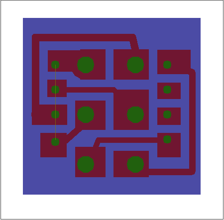
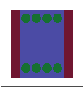
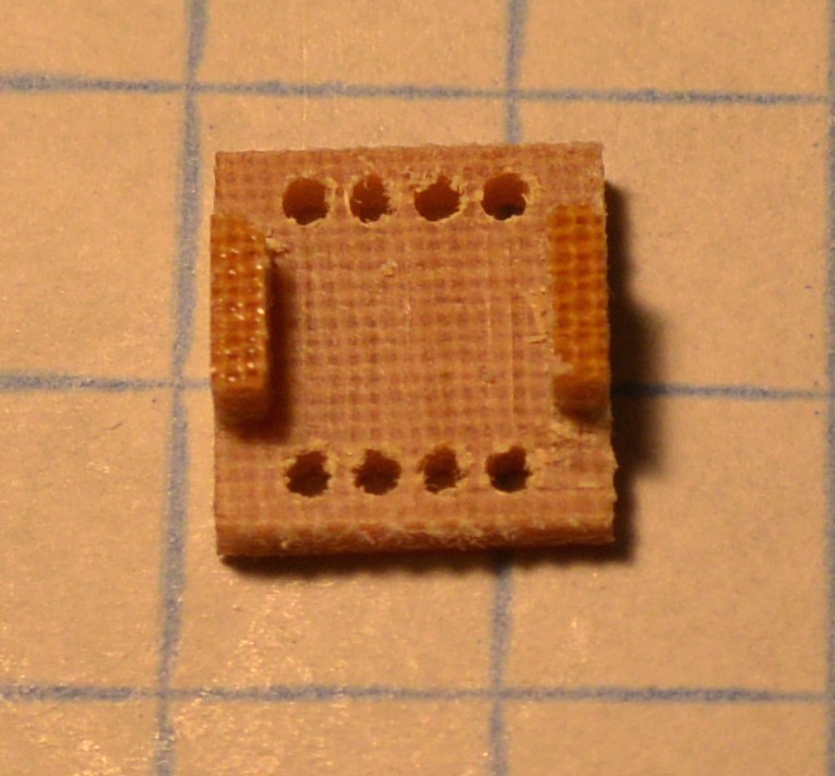
The images above show the Eagle board (left) and the clamp part as milled (right.) Actually the part shown on the right has shorter tabs than the part shown on the left and reflects an earlier design. The longer tabs seem to be more succesful in locating the programming connector on the chip and are used in the currently documented design.

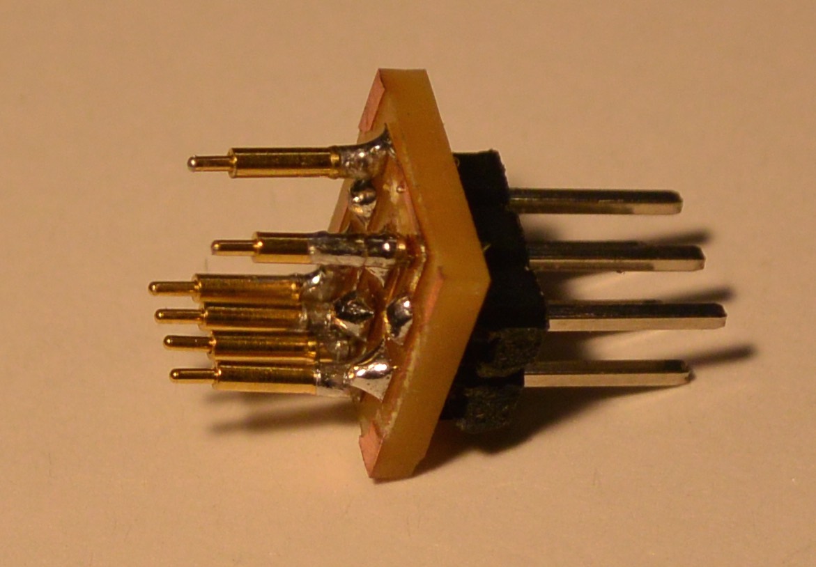
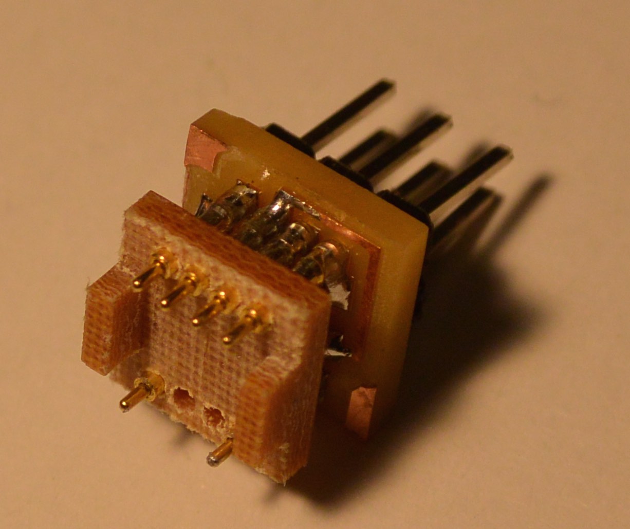

Above, photographs of the top board with pins inserted, the top board with pins and header, and the assembled connector. At bottom, the connector is used to program a t45 chip on a board with no external programming connector.
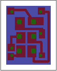
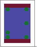
Assembly is done as described above for the t45 connector.
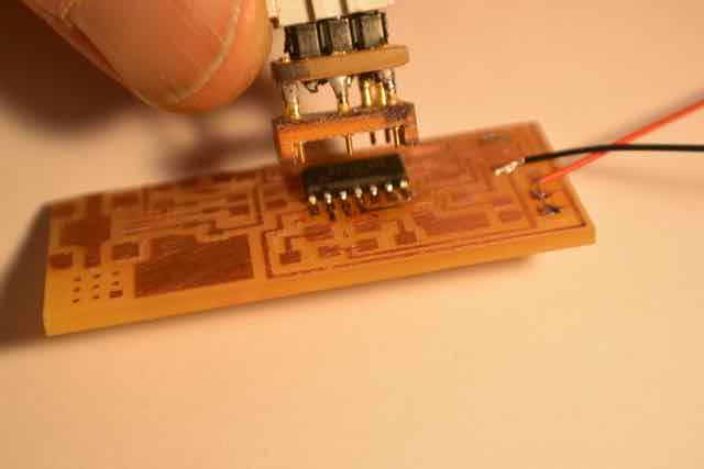
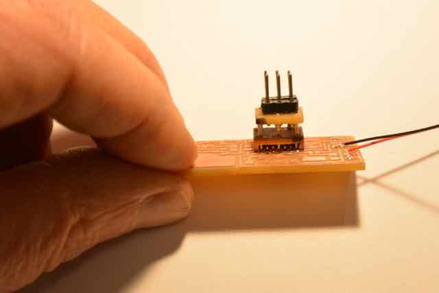
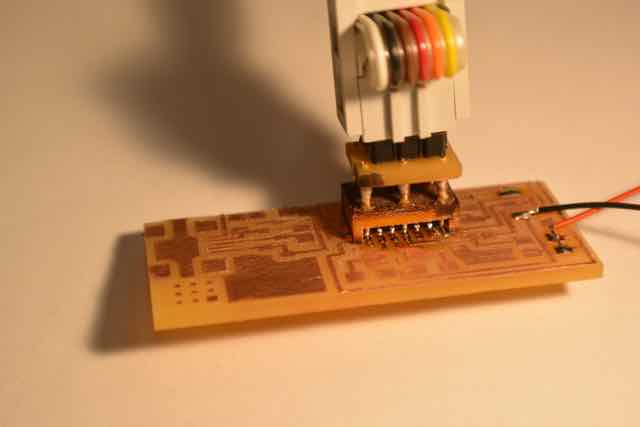
On the left, the assembled connector is lowered onto the t44 chip, which is powered through the attached wires. Middle picture shows the black dots to mark ground on the boards. Right picture shows the clamp on the chip, programming with no external components on the board. If the clamp matches the chip dimension well, connector can be maintained in position by friction and does not need to be pressed down while programming.