From Last Week
I got stuck into a basic problem of having my microcontroller timing precise: I had added crystals, changed parameters for Serial communication multiple times and, in the very end, got it working by using pure C code. Nevertheless, the other day I realized something crucial: maybe I was not "telling" my arduino code to run with a 20MHz crystal. I definitively was doing so when using AVRdude to upload to Attiny44, but I noticed there's no single line of code in my Arduino source that was doing this. Then, I remembered a simple, almost stupid step that I was forgetting.
Yes. Burn the bootloader.
Simple like that. I chose the 20MHz board, burned the bootloader and uploaded the code: it worked beautifully.
In the example below, I'm constantly sending a message from the board to the compute, while, at the same time, listening for a sent message that calls for the LED to light up.
Nevertheless, I will spend most of my coming week studying ESP8266: since I couldn't use a nice BLE plugin (see last week) to directly communicate with the boards straight from the browser (also note that I have a windows), I decided to have the physical modules' data being pushed and pulled from a log file (simply a file in which I'll keep a log of actions). Each physical module will either get or post data using an ESP8266, whereas each of its corresponding digital mod will will virtually represent a physical module by pulling and pushing from the same database.
ESP8266
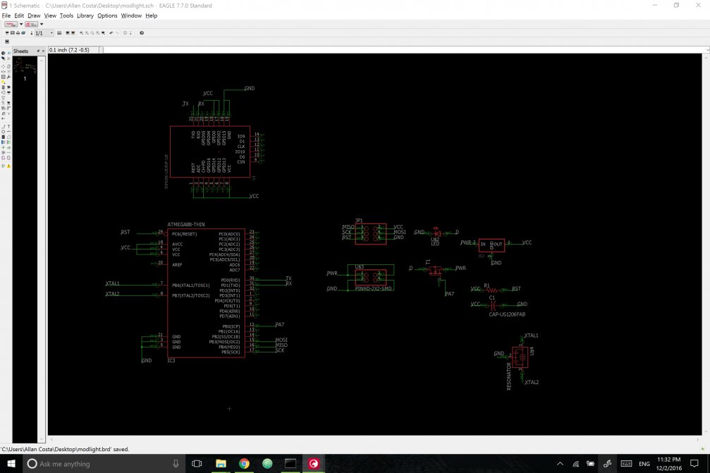
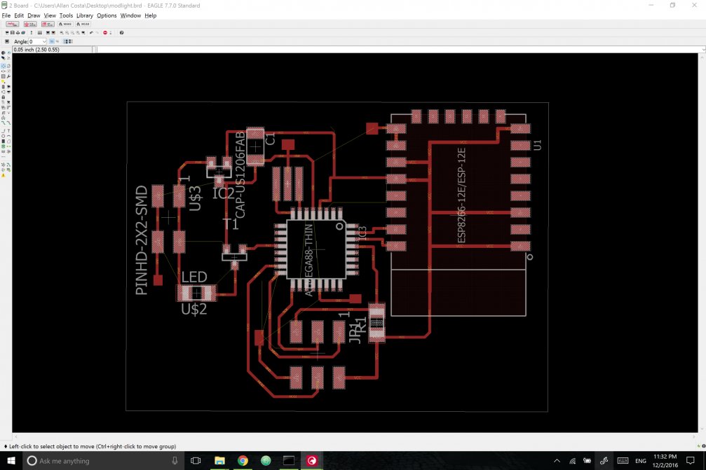
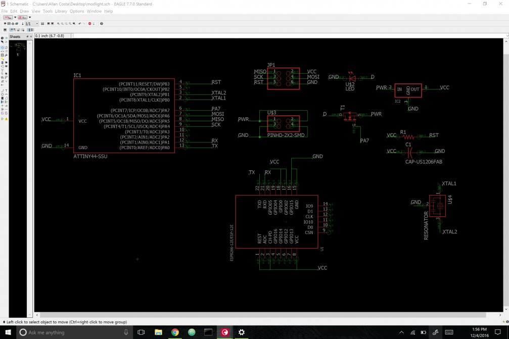
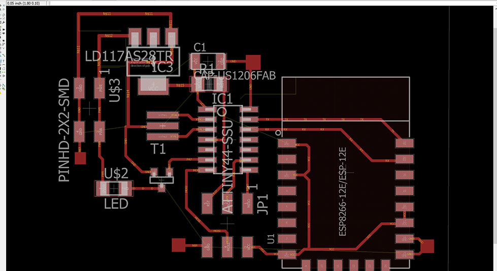
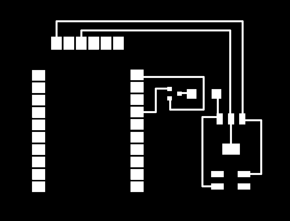
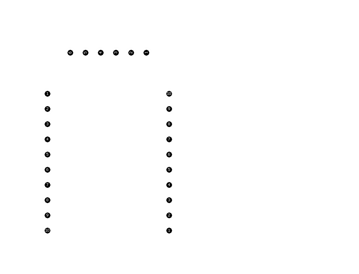
I'll be using ESP8266 modules to accomplish data pushing and pulling from servers. At the shop, we have the version which doesn't come with capacitors or resistors of its own, and I'll have to create a whole board with a microcontroller to appropriately communicate with it. I drew most of the circuitry by basing myself on the Hello.FTDI from embedded programming week, as well as on this week's board for communicating (from a computer) to ESP8266. Since I wanted to play with Atmega88 (I've been using attiny44s since I started designing boards), I will use it as a microcontroller for this design. Here's the designing process and the boards I've got.
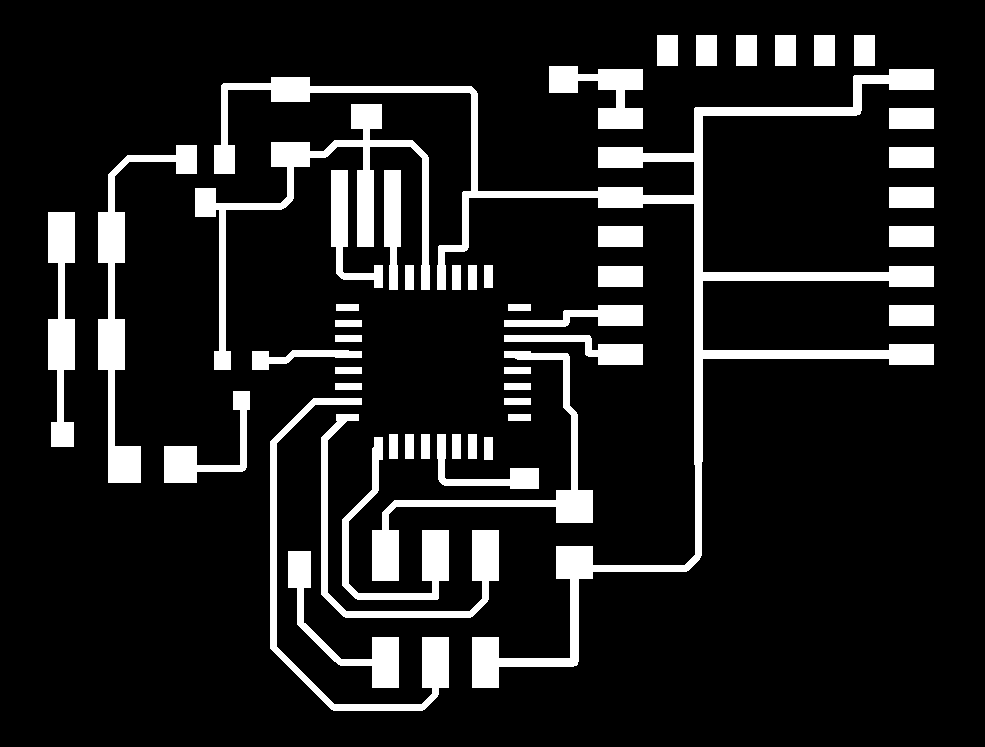
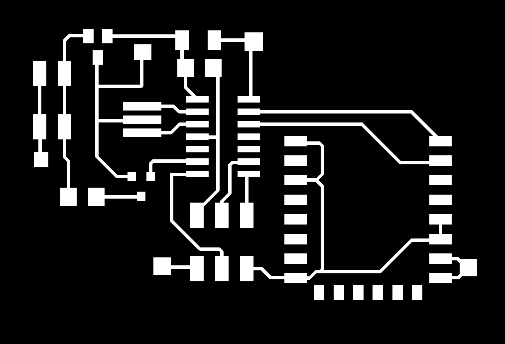
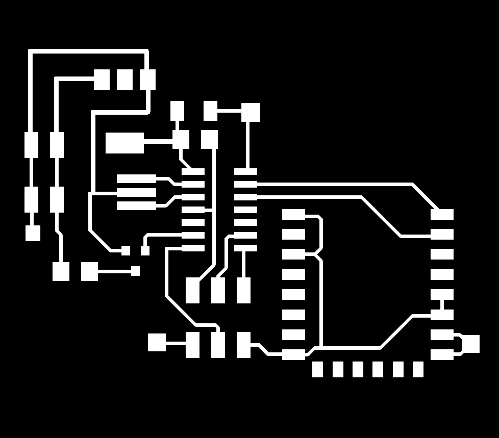
And here are the .png files:

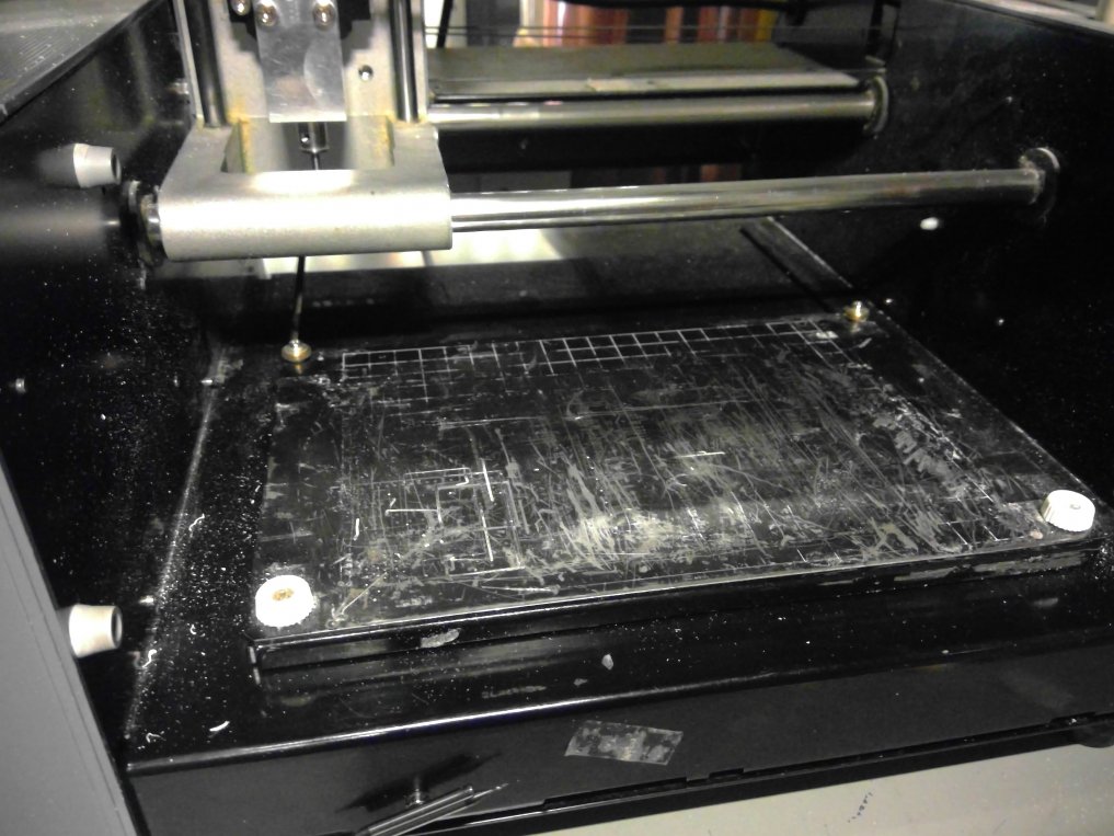
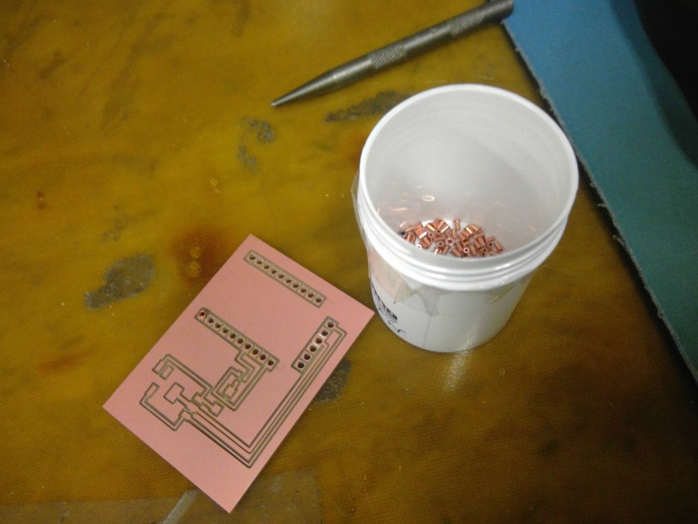
Boards were being milled way way deeper than supposed to.
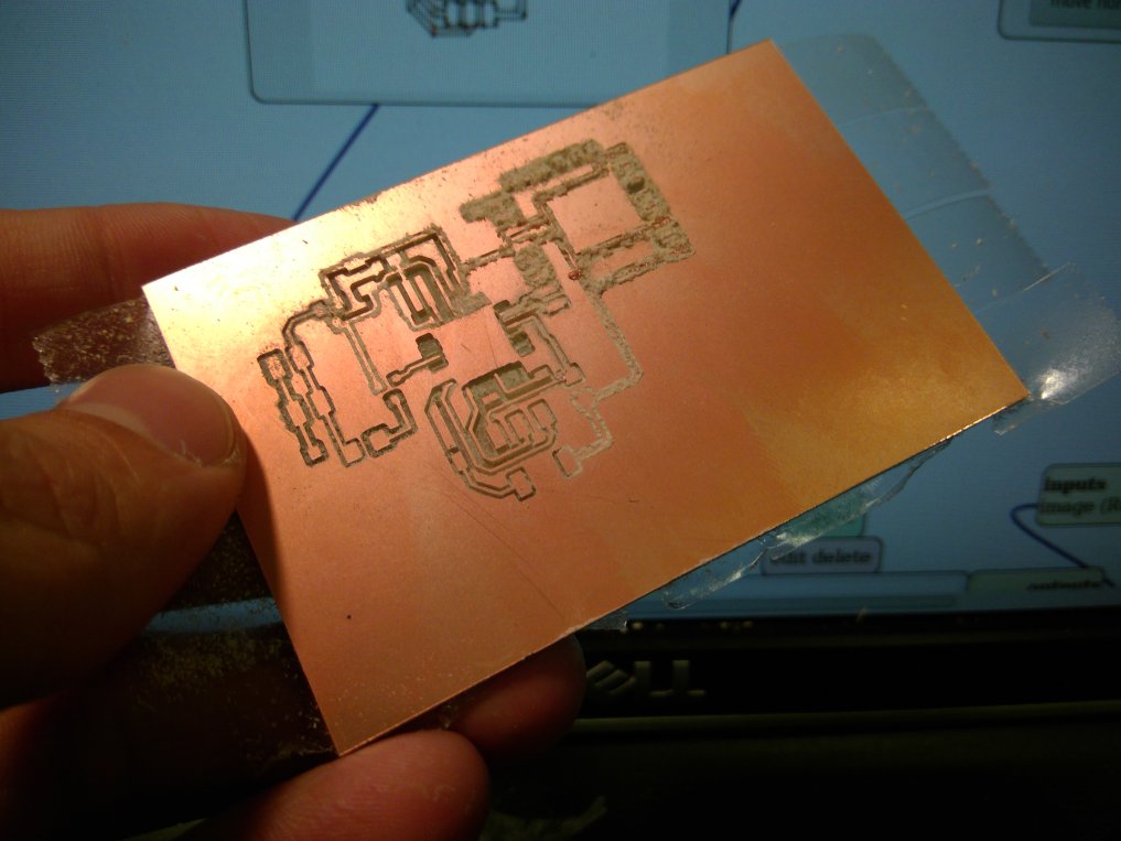
I reduced the cut depth significantly, and got:
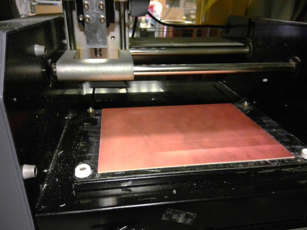
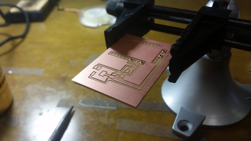
The sacrificial layer is somewhat inclined. Surprisingly, this was the case not only for one of the milling machines at the shop, but for both of them
To confirm this, I simply changed the sacrificial layers and tried it again.
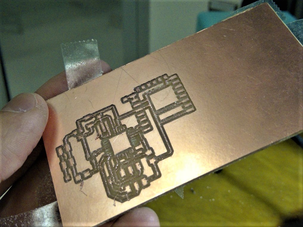
Far from perfect, but definitively much better. It's still not very smooth because the end mill was clearly far from ideal. I changed the end mill and finally got it right. However, a big issue that arose was on the gaps between pins of the atmega88: they were simply not being cut in some cases, or cut "too much" in others - milling the pin's copper itself. Since I had another version of my board for an attiny44, I decided to give it a try and leave the atmega for coming weeks. Here's the design process, once again:
And here are the png files:

After soldering all the components, here's what I've got:
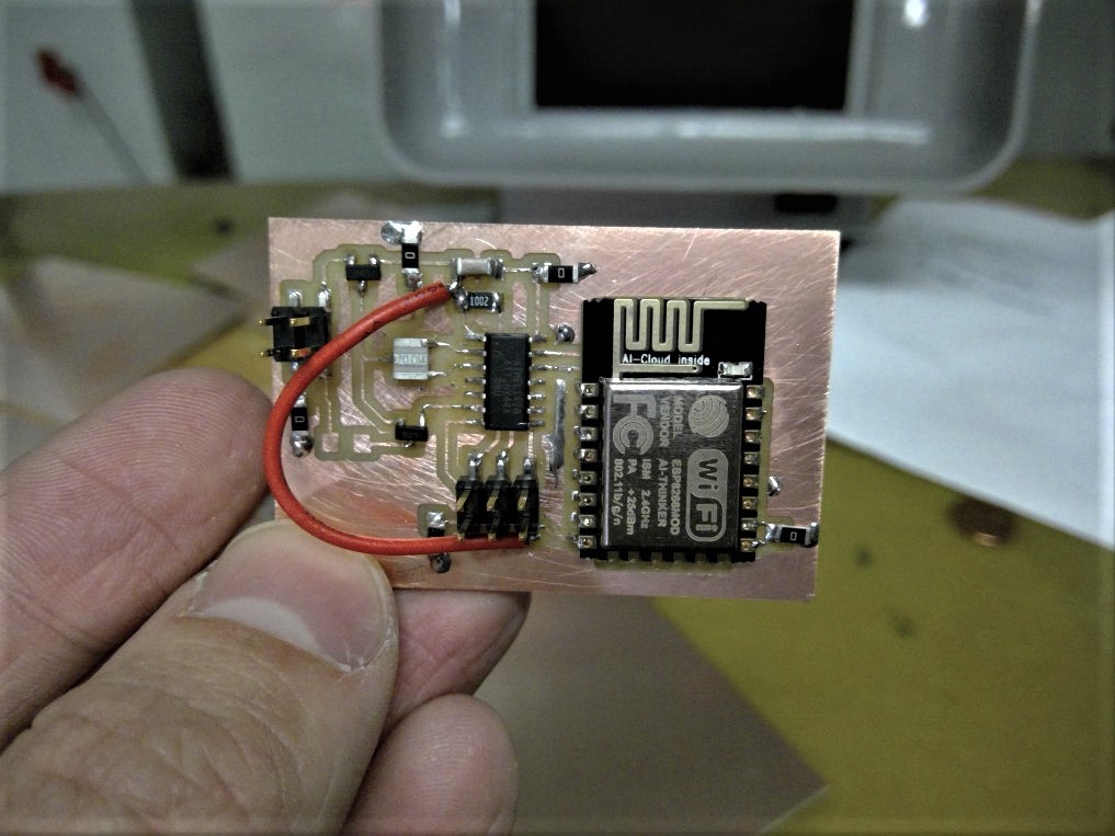
It didn't work. One of the TAs saw my board and promptly pointed to the reason: Wifi modules usually draw much current, but my own regulator didn't allow for this (and this explained the huge regulator Neil had soldered in his board).
Back to Eagle:

Now, ready to start soldering, I discovered that we have new ESP8266s. Rather than having the smaller piece we were using last week, CBA section has bought fully integrated ESP8266 circuits (Adafruit's Huzzah) that easily communicate with an FTDI cable. So I have no other option than to give up on my original PCB for this week and start programming directly on Huzzah.
Huzzahs
Adafruit and Sparkfun highly recommend such programming Huzzahs directly, despite what the class says. I followed Sparkfun's recipe to get Wi-Fi communication that would be printed in the Serial port, and got it working after just some couple minutes.
In the process, I came across a very interesting platform called Phant, set up by Sparkfun, that allows simple data to be pushed and recovered with simple JSONP requests. Surprisingly, this is exactly what I planned to have for my modified version of mods (it's worth noting that I played a bit with PHP before realizing the CBA is not very fond of it). Now the goal is simple: setting up this API, having my circuit getting information from it, and having a digital module pushing information into it. To test this, I'll start producing my first simple "physical module", a light-emitter one. To set up it, you can simply get into Phant's webpage and create a simple database; you add the tags and type of information it expects, and right after you should receive a public (to get data) and a private key (to push data). This works then by simply using GET requests:
To get "light1" values that were pushed since the database creation, for example, you can use this:
https://data.sparkfun.com/output/VG6K1EVjgnIMmK7xNz5M?page=1&eq[mod]=light1
To push "light2" values for example, you can use this: [WON'T WORK FOR MY PRIVATE KEY IS NOT THERE!]
https://data.sparkfun.com/input/VG6K1EVjgnIMmK7xNz5M?private_key=hue&mod=light2&value=20
on the boad side:
I downloaded the board for Huzzah and used it as a base to start designing a PCB:
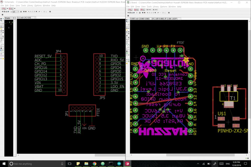
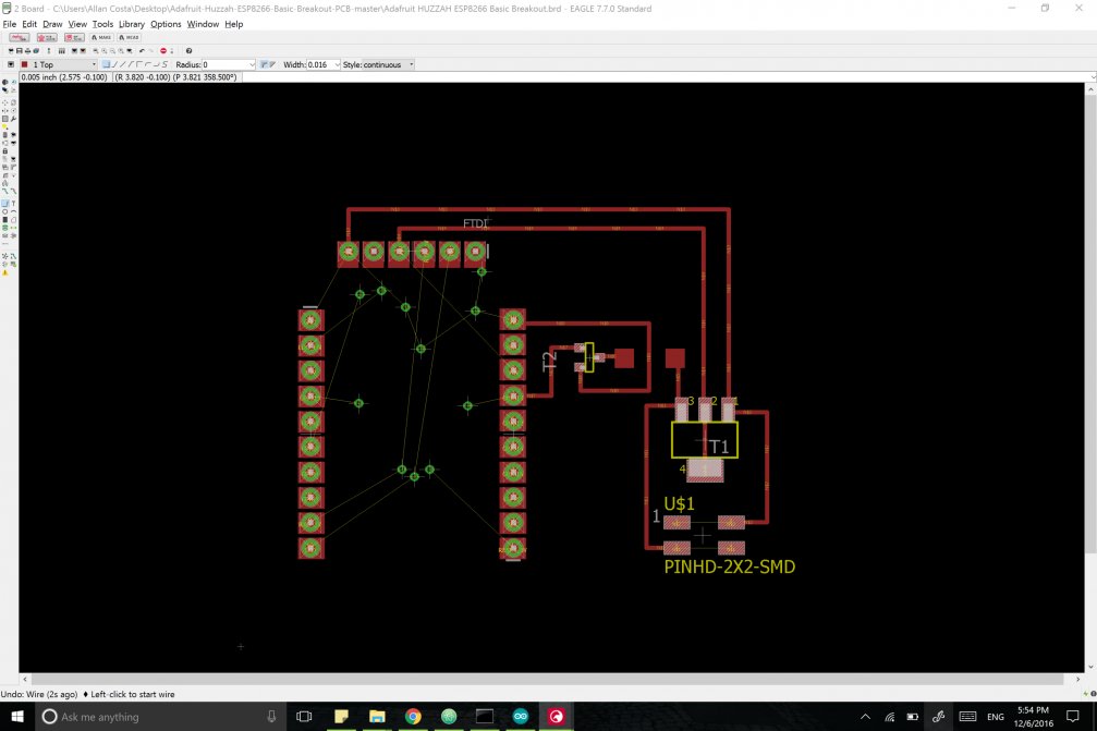
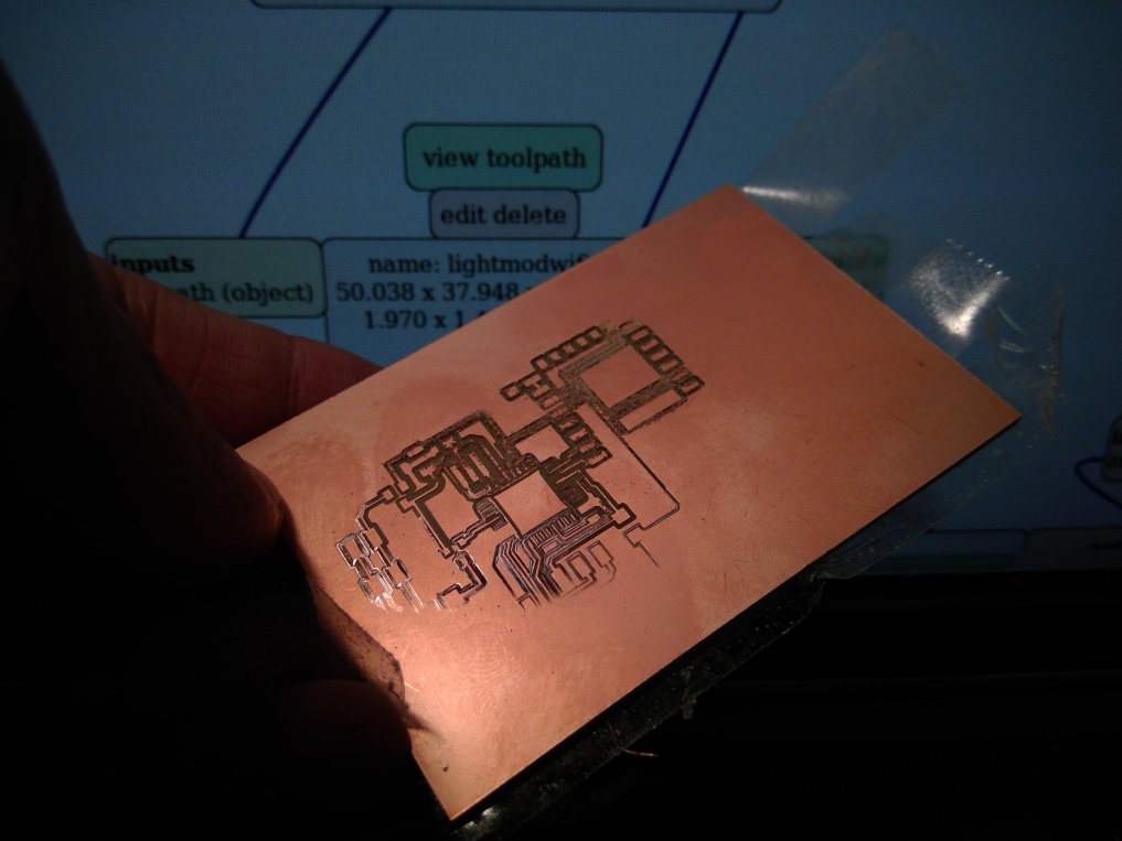
Here's the PCB design:
Milling vias were kind of trickier: I had to play a bit with photoshop to have them small enough for the paths not to go beyond necessary when processed by mods. Here's what I've ended up with:
And here's the soldering process:
Finally, final board:
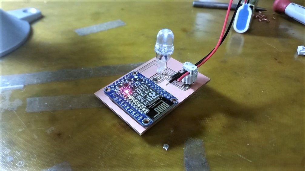
I then uploaded code straight from the Arduino IDE:
 #include

 const char* ssid     = "MIT GUEST";
 const char* password = "";

 const char* host = "data.sparkfun.com";
 String publickey = "VG6K1EVjgnIMmK7xNz5M";
 String privatekey = " this is private bro :) ";
 String format = ".json";
 const int led = 0;


 void setup() {
   pinMode(led, OUTPUT);
   WiFi.begin(ssid, password);
   while (WiFi.status() != WL_CONNECTED) {
     delay(40);
   }
 }

 int value = 0;

 void loop() {
   delay(1000);
   WiFiClient client;
   const int httpPort = 80;
   if (!client.connect(host, httpPort)) {
     return;
   }
   // We now create a URI for the request
   String url = "/output/" + publickey + "?" + "page=1&eq[mod]=light1";
   // This will send the request to the server
   client.print(String("GET ") + url + " HTTP/1.1\r\n" +
                "Host: " + host + "\r\n" +
                "Connection: close\r\n\r\n");
   delay(1000);

   // Read all the lines of the reply from server and print them to Serial
   while(client.available()){
     String line = client.readStringUntil('\r');
     if (line.substring(1,4) == "mod"){
           int valueStart = line.indexOf(",", 20);
           int valueEnd = line.indexOf(",", valueStart+1);
           String value = line.substring(valueStart+1, valueEnd);
           int analog = value.toInt();
           analogWrite(13, analog);
       }
     }
 }
This code is checking the database, filtering for its' type (in this case, I called this mod "light1"), and changing the value according to the last pushed data.
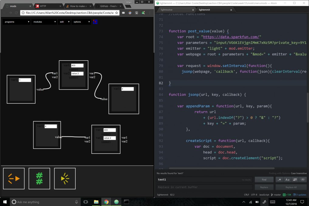
Database + Mods
Now it's very simple to create mods that will track, push and pull from this database; For this case, I created my own version of a module:
(function(){
var mod = {}
var name = 'lightemitter'
var init = function() {
mod.value = 0;
mod.emitter = 1;
}
var inputs = {
value: {type:"integer",
event: function(evt){
mod.value = evt.detail
post_value(mod.value)
}
}
}
var outputs = {
}
var interface = function(div){
mod.div = div
div.appendChild(document.createTextNode('var1: '))
input = document.createElement('input')
input.type = 'text'
input.size = 6
div.appendChild(input)
mod.emitter = input.value
}
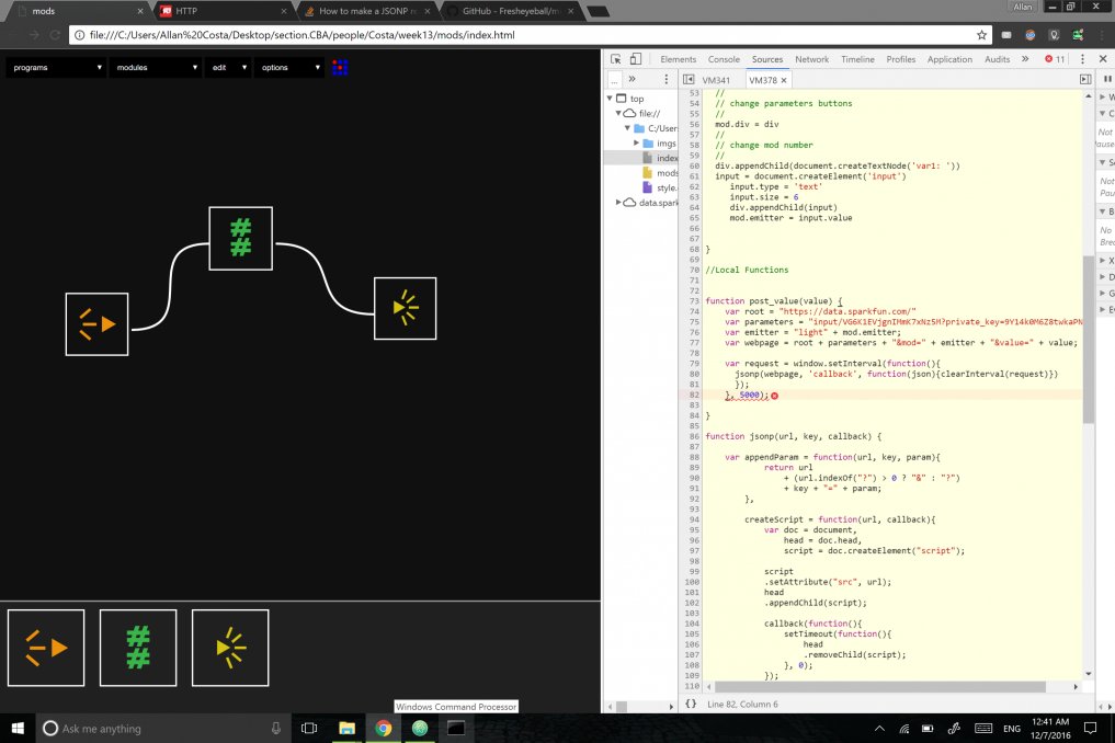
function post_value(value) {
var root = "https://data.sparkfun.com/"
var parameters = "input/VG6K1EVjgnIMmK7xNz5M?private_key=9Y14k0M6Z8twkaPNAMKw"
var emitter = "light" + mod.emitter;
var webpage = root + parameters + "&mod=" + emitter + "&value=" + value;
var request = window.setInterval(function(){
jsonp(webpage, 'callback', function(json){clearInterval(request)})}, 5000);
}
function jsonp(url, key, callback) {
var appendParam = function(url, key, param){
return url
+ (url.indexOf("?") > 0 ? "&" : "?")
+ key + "=" + param;
},
createScript = function(url, callback){
var doc = document,
head = doc.head,
script = doc.createElement("script");
script
.setAttribute("src", url);
head
.appendChild(script);
callback(function(){
setTimeout(function(){
head
.removeChild(script);
}, 0);
});
},
q =
"q" + Math.round(Math.random() * Date.now());
createScript(
appendParam(url, key, q), function(remove){
window[q] =
function(json){
window[q] = undefined;
remove();
callback(json);
};
});
}
return ({
name:name,
init:init,
inputs:inputs,
outputs:outputs,
interface:interface
})
}())
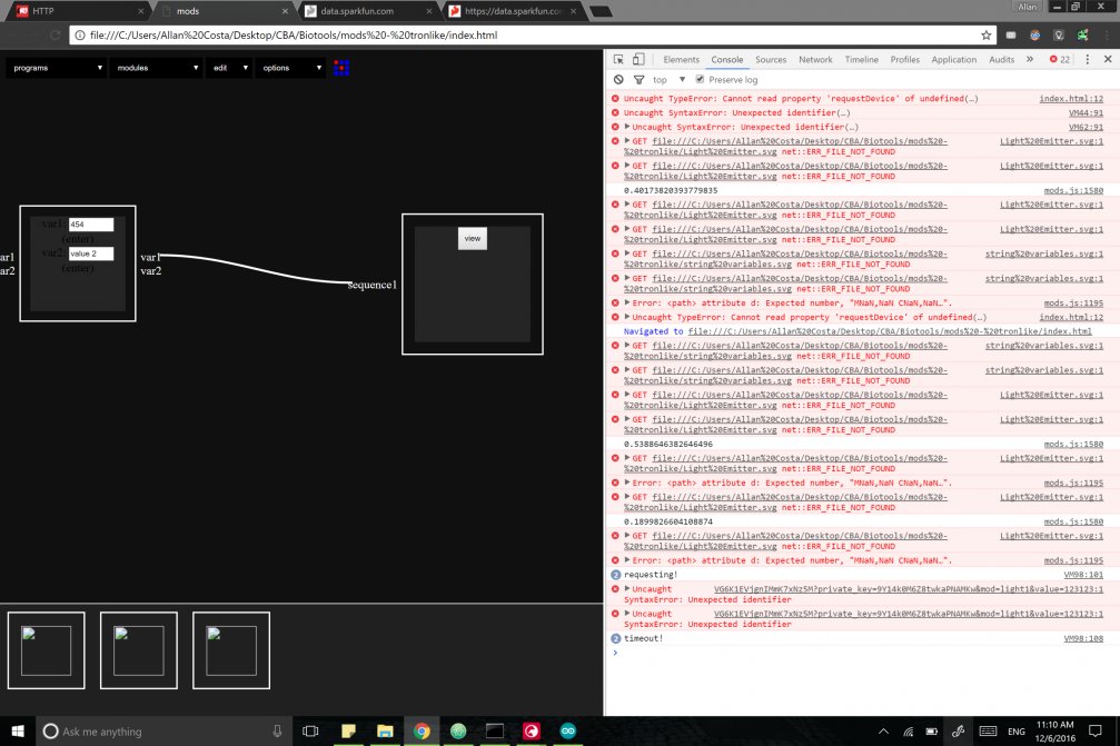
And finally, I can interface my digital module with my physical module. For this case, it's responding to values that directly will change the lighting pattern:
Simple data push into the server
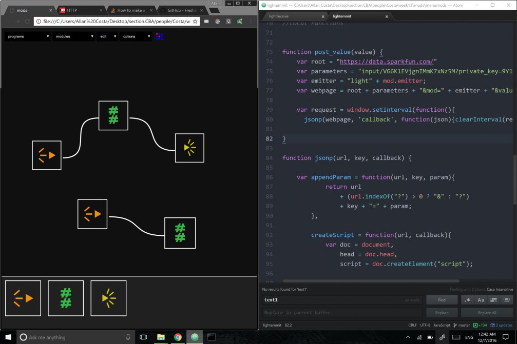
Getting value from a physical (light receiver) module, having it printed, and then pushing it into other physical (light emmiter) module
Finally, getting value from light mod 1 and passing it to mod 4, and then getting value from mod 4 and printing it.
One major issue that emerged with the Phan API was its instability. Often times it would stop responding to requests, and even more commonly it would take more than 5 seconds to respond to a request. Although I used it for simplicity and time-saving reasons, I'll be setting up a simple python server app (using Flask) for the final project.