Final Project: magbot
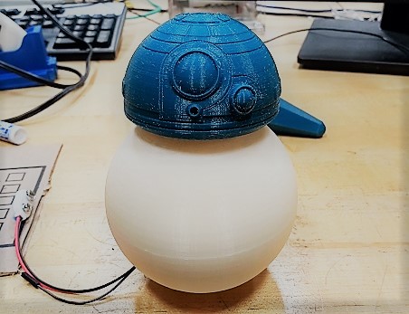
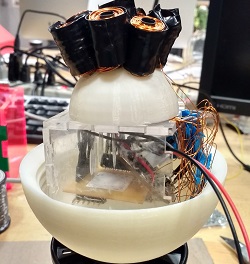
I built a robot with a magnetic head that is actuated by electromagnets within the body. This mechanism is similar to the way the Megabot in Big Hero 6 and BB8 in Star Wars seem to work. The electromagnets are controlled from an interface on my computer that communicates with the robot over Bluetooth.
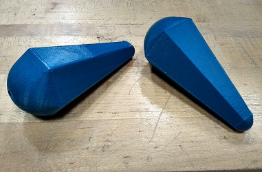
I used an electromagnet arduino instructable and the Boogie Box instructableto build this robot. I also found a screwball 3D printed part, a BB8 head printed part, an origami BB8, a box maker and the Fabkit to support the development of this project. In addition to integration, I also designed a spherical electromagnetic harness, an h-bridge board, 3D printed megabot ears, and vinyl stickers.
Materials and cost
-
Base and enclosure
- Electromagnet harness - Mojo 3D printer - $2
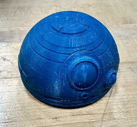
- Screwball dome top - Mojo 3D printer - $10
- Screwball dome bottom - Mojo 3D printer - $15
- Acrylic box enclosure - GCC laser cutter and scrap acrylic
- Vinyl stickers - Roland vinyl cutter - >$1 Electromagnets
- 9 M5 (10-32) 1-inch screws - $0.90
- 9 M5 nuts (optional)
- 10-32 Heatshrink tubing - >$1
- Black conductive tape >$1
- 30 AWG magnet wire - $9 Electronics
- ATMega 168A - $2.50
- Copper clad board - $5
- 6 A4953 H-bridges
- HM-10 BLE module - $10
- 9 Volt battery or power supply - $10
- Male/female bullet connector - $0.50
- Capacitors - $5
- Resistors - $1
- LED - $0.01
- 2x2, 2x3, 1xn Headers - $1
- Jumper wire with crimps and headers - >$1
- Push button - $0.91
Base and enclosure
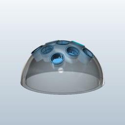
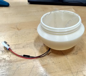
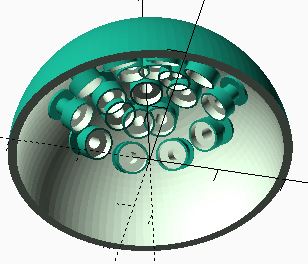
The base that I used and the base that I recommend are slightly different. The one that I used I found very early on in my project. It was inteded as a harness for a BB8 robot, although the author never finished his robot. The dimensions I printed were 2" x 2" x 1" so that it would be small enough to fit in my dome. Later on I designed another base that can hold up to 22 electromagnets and covers more area. I wanted to get the project working with fewer electromagnets before I scaled up.

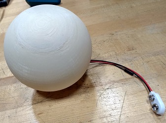
The spherical enclosure was based on a screwball design that I found online. I remade the screwball in Fusion 360 and printed it with dimensions 4" by 4" by 2", making a sphere of radius 2" on the outside and about 1.8" on the inside. To decorate the enclosure I made vinyl cuts of BB8's body and Megabot's faces.
The plan was to use 3D printed versions of BB8's head and Megabot's arms to attach to the magnets and move around. However, my electromagnets were not nearly strong enough to carry them. The force of gravity and momentum could dislodge my weakest magnets even if they had nothing on them. So, I improvised and found an origami BB8 head to put on top of the magnet. I think that if I could make the entire base of the arms or head magnetic, rather than just a single point in the middle, I would have had more success.
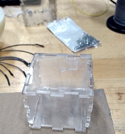
To package the electronics and the electromagnetic harness I laser cut an acrylic box that fit within the sphere enclosure. This made it possible to hold the harness up against the surface at the tops of the sphere. The dimensions of the box were 2" by 2.5" by 2.5" and it fit just within the sphere.
Electronics
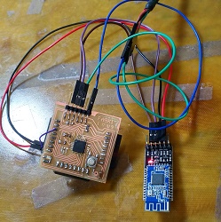
There are three separate boards in this project: the main microcontroller, an H-bridge board, and a HM-10 BLE module. Of these, I designed the H-bridge board, made the main microcontroller, and the HM-10 came fully assembed.
The main microcontroller design is a Fabduino. I decided to use this board because it broke out all of the pins on the ATMega 168A and was compatible with a bootloader, which means no need for a programmer. As I mentioned in Week 13 I had a problem where I could not load the boards.txt file from the Fabduino page. Instead, I used the MiniCore Library.
Packaging the electronics required me to solder all of the components onto the Fabduino. I wrapped the bluetoth module in cling wrap to prevent it from shorting out any traces on the board. Next, I made jumpers to go to plug into the h-bridge board and soldered them onto the Fabuino.
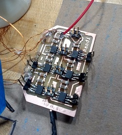
The first iteration of my A4953 H-bridge board occurred in Week 11, and the new one is similar. The new board does not include a microcontroller and it does incude capacitors on every H-bridge and headers to access the inputs and outputs. The one that I used does not have those headers, I soldered each of them directly to the h-bridge pins. This is updated in the project files though!
After designing, milling, and stuffing the board I tested it with an oscilloscope. One problem I had in output devices week was that my electromagnets had so few windings that when I ran 9 volts through them they totally destroyed the H-bridges. A4953 chips have an output current limit of 2A and my electromagnets required more than 3A. Lesson learned: check the electromagnets on a power supply to see what kind of current they are pulling.
The breakout board includes a connector for a 9V-battery and a voltage regulator. This powers the microcontroller when it is not connected to the computer. Connect the red and black jumpers to any VCC and GND to make this happen.
Electromagnets
In class, Neil presented me with the idea of using electropermanent magnets to control the movement of the arms. I liked this idea and looked at Ara Knaian's thesis that describes electropermanent magnets and a motor he designed around them. However, I felt that I was not quite prepared to go down this road, so I decided to adjust and use electromagnets as the basis of my motor.
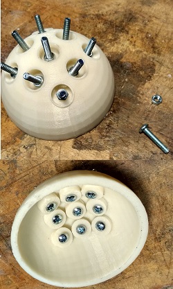
I used M5 1 inch screws with nuts as the core of the magnets. I used a drill with an 11/64 inch drill bit and 10-32 tap to make the holes in the harness. If you mess up the angle of the drill you will have a hard time later on. So I recommend printing the base that I designed (not the one I used) since the holes are already there. You should probably still at least tap them. I secured the harnesses with a nut. On the smaller harness the nuts actually were not necessary because of the tight fit. But, I still used hot glue to keep ot secure.
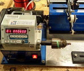
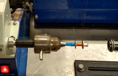
I then made 600-loop coils on a 1 inch length of heatshrink. These were easy to slip on the metal cores to make some seriously strong electromagnets. I used the coil winder because I had very small nails to wrap. Eric VanWyk has a great tutorial on how to use it. Finally, I wrapped the coils in black electric tape to keep them together. Keep in mind that electric tape is not a great idea. If you have heat shrink to put on the coils that is much better. Each coil ended up having a resistance of 5-7 ohms!
Programming
I used the Arduino IDE to do the embedded programming. A software serial object communicates with the BLE module. The program simply reads in commands over bluetooth and changes the state of each electromagnet, then updates all electromagnets according to their current state. Since I used H-bridges with two electromagnets on each, only one of the pair can be on at a time. (H-bridges are usually used to make motors go forward and reverse.)
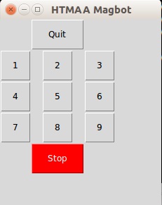
In Week 13 I talked about how I wrote a BLE terminal for my computer. For the final project I extended that to include a Tkinter interface for sending commands through BLE. The interface includes a button for each of the positions the electromagnet can be in and a Stop button. Since I was playing around with using up to two magnets on the robot, the interface allows the user to select how many magnets they have.
Conclusions
This project demonstrates CAD, 3D printing, vinyl cutting, laser cutting, electronics desgin, embedded programming, application programming, networking, and machine design. I learned how to make electromagnets, package electronics, and not overheat my final project (for the most part). Some of the biggest problems I had included burning h-bridges with too much current, smoking boards because of shorts, and dealing with the imperfections of 3D printing as well as those of making everything by hand. The electromagnets had very different strengths and are pretty high maintenance.
The ultimate goal of this project was to show that I could control at least one magnet with an array of electromagnetic coils. Unfortunately, the electromagnets (running only on 9W) were not stronger than the force of gravity. This made attaching anything to the magnets difficult, and they often fell off the sphere due to their own weight an momentum. However, I believe that with more power and better electromagnet control this project is well on its way to making a megabot or BB8!