Week eleven:output devices
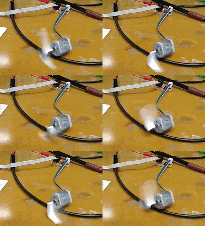
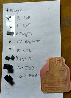
For this week I designed my board to control the electromagnets that I will use in my final project. I decided to design an H-bridge board with two H-bridges. That way I will be able to control up to four electromagnets on one 2x2 Header.
I managed to successfully run a motor on the H-bridges by editing the example code. However, when I tried to use my electromagnets they overheated the board and ruined the H-bridges.
Instead of making a design so similar to the example one, I should have used an FTDI header so that I can control the motors from a computer.
One important thing to not forget is to use capacitors on both H-bridges. I only used one set of capacitors, so this could be a reason why the electromagnets did not work.
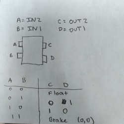
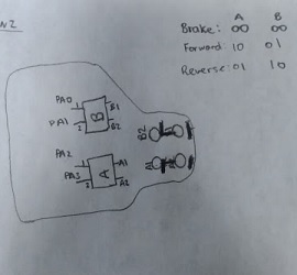
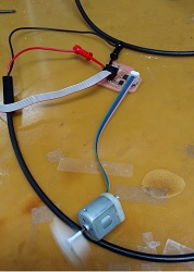
The code for controlling one motor with two H-bridges relied on understanding the functionality of the H-bridges. Essentially, writing 01 on the inputs creates 01 on the outputs and writing 10 on inputs creates 10 on the outputs. So, since a motor needs a 0 on one lead and a 1 on the other lead to run, I had to wire the motor such that one lead was connected to H-bridge A output 1 and H-bridge B output 2. The other lead of the motor was connected to A output 2 and B output 1. In the code I wrote 10 to A and 01 to B for forward, and 01 to A and 10 to B for reverse.
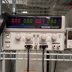
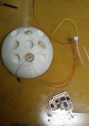
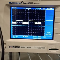
When I tried to run the code with electromagnets connected (weak magnets with magnet wire coiled around them, wrapped in tape) there was a fuzzy ringing sound. On connecting the outputs to the oscilloscope I realized that the ringing sound came from the H-bridge outputs. The components were hot and totally fried. I was afraid of that so I only turned the electromagnets on in short pulses (500 milliseconds on, 1000 milliseconds off), but alas we are back to square one.