Week three: electronics production
When it came to life...
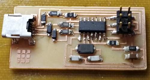
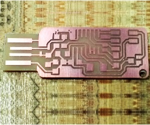
This week our assignment was to mill, solder, and program our very own ISP (In-System Programmer) to be used later on in programming our custom PCBs. I have made PCBs before, but I used caustic chemicals and photoresistive material, never a mill before. This is also my first time soldering surfance mount (aka super tiny) devices. Don't let the picture deceive you, the real board is 1" by 2" and the pieces seem microscopic.
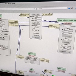
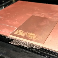
The mill we used is the Roland MDX-20 Model A. We used a 1/64" endmill to drill the traces and a 1/32" mill to cut out the board. Using Neil's fab modules we can upload a png containing the traces and then the outline for the mill to cut out.
Here's a quick summary of how to mill:
- Lay down a sacrificial layer, a large copper-plated material placed on the bed of the mill. This layer will accumulate cuts and prevent them from going into the bed of the mill.
- Place double-stick tape on the board that you want to mill. Be sure the tape bottom of the board and the tape are as clean as possible. Place the tape with minimal overlap and spaces. Leave some excess tape hanging off the sides of the board for easy lifting.
- Firmly attach the board to the sacrificial layer. And I mean firmly. If the board is not very stuck to the sacrificial layer, then it could come up partway through the job - then physics takes over.
- Adjust the xyz positioning of the endmill. The xy-position is controlled using Neil'f fab module. Make sure that the endmill rests over the board and that your chosen design will not cut outside of bounds. The z-position of the endmill should allow it to gently touch the surface of the board.
- Calculate the job and send the file to the mill.
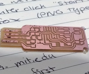
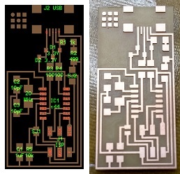
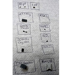
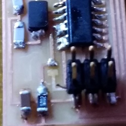
With a freshly milled board, the next step is to solder components onto the board. Refer to the board outline that shows the parts and where they are located. It is a good idea to get them one at a time, or label them in some way.
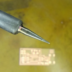
The easiest way to solder quickly is to use a clean, shiny soldering iron tip. Use water and a sponge to wipe off the tip and then coat it with a bit of solder. The soldering iron should be at 650°F to quickly melt the solder without burning the components. I recommend soldering this way: touch the pad with the soldering iron and wait a moment. When the pad is heated, touch it with the solder as well so that a bit is on the pad. Leaving the soldering iron on the pad, use tweezers to move the component in place. Then, remove the soldering iron so the component is set. Solder the other end of the component to the board, then resolder the initial joint. The solder should cover the pin of the components completely and it should look nice and shiny.
Some components are very, very small and you may connect two pins that you do not mean to. When this happens, use the soldering braid to remove excess solder. This works better with a larger sodlering iron. Lay the soldering braid over the place where you wish to remove solder. Touch the braid with the soldering iron and wait for the solder to liqueify beneath the braid. Quickly remove the soldering iron and the braid (careful, it is hot!) at the same time. If you are not quick enough the braid may get stuck or you may rip up traces on the board. This is something you get better at with practice.
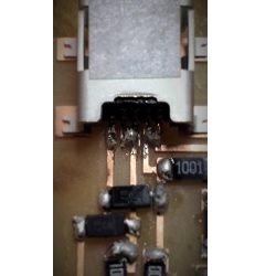
The last step is the program the board. Simply follow the programming instructions given on the project page. If you're using the AVRISP and the indicator LED is staying red, then check your connections. I had a problem with the mini USB connector not being soldered to the pins, they were floating millimeters above the path.
If the LED is green but the board will not program, pay attention to the error messages. They are very descriptive.There could also be a problem with stray globs of solder connecting two paths. Always do a visual inspection first, do not just rely on the multimeter. And ask a friend for help if you need a second eye.