Week five: Electronics design
When it got a brain...
This week our assignment was to design an make a Echo board with an added LED and button.
Step One: Design
I decided to use the Eagle software because it was so similar to the Cadence software that I have designed boards on before.
Make a New Project
- Open the Eagle software and go to File > New > Project
- Right-click the project and choose New > Schmeatic
Importing the Eagle Library
- Download fab.lbr by right-clicking the link and choosing "Save link as..."
- In the open schematic window, go to Library > Use > fab.lbr. Now this libary will appear when you begin to add components. This library contains all of the schematics and the board footprints for the pieces we will use.
Adding Components
- In the open schematic window go to Edit > Add... (the tool is also available on the right toolbar).
- The window that opens will show a list of libraries with a drop-down arrow nex tto it. Look for 'fab' and expand its drop down.
- Add components by selecting them. Let's start with the ATTINY44. It has three options so there is a drop down arrow next to it. We want the SOIC package because that is the one that matches the component we have in the lab. Double-click the SOIC14 open.
The 'Add...' window will close and you will be able to place the schematic by clicking once. A right-click will rotate the component. Since we only need to place one ATTINY44 then we use 'Stop' (look for a red circle with a white line through it on the toolbar above the schematic window). - Now we will place the rest of the parts. We need:
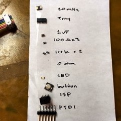
- 1 ATTINY4
- 1 LED
- 1 1uF Capacitor 1206FAB. This is the bypass capacitor between VCC and GND
- 2 10K Resistors 1206FAB. One is a pull-up resistor for reset, the other is a pull-up for our button.
- 1 499 Resistor 1206FAB. This is a current limiting resistor for the LED.
- 1 Button
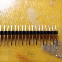
- 1 FTDI Header
- 1 ISP Header
- 1 20MHz Crystal
- Add resistor and capacitor values by right-clicking the component and choosing 'Attribute'.
- Press 'New' and type in a value and name for the resistors.
- Use the Edit > Move command to place components near one another in the schematic. One click selects the component (it will become bright red) and it will follow your mouse until you click again. A right-click will rotate the component.
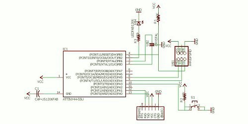
- Use the Draw > Wire command to connect components to one another. The picture of the schematic shows which components should be connected.
- Use the Add command to place power and ground. Use the +5 and GND symbols from the supply1 or supply2 library.
Creating the Board
- With the schematic window open, go to File > Switch to Board.
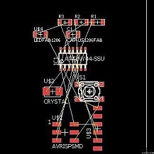
- Choose 'Yes' to create a new board from the scematic. A board window will appear with the footprint views of all of the components. The yellow lines show connections that need to be routed between the components.
- Use the move tool to start placing components on the board. Start by placing compnents that need to be on the edge of the board like the FTDI header.
- Next, place components that have a lot of connects, like the ATTINY44 more in the middle of the board. A right-click will rotate a component, so orient it in sucha way that yellow lines intersect as little as possible.
- Place the rest of the components in such a way that you minimize the size of the board and the length that routes will need to travel to get to components.
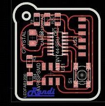
- Use the 'Trace Routes' (and the 'Ripup Traces') command to make connections between the components. The thickness of the wires should be 0.016 (slightly larger than the 1/64 endmill) As connections are made, the yellow lines disappear. Be patient and creative.
- Once everything is nice and routed, you need to add an outline. Use the Draw menu to choose shapes. The width of the lines should be 0.032 inch (slightly larger than the 1/32 endmill).
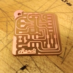
- Place your name or a cool logo on the board.
Exporting the Images
- Now we need to save the traces and outlines as PNG files. Go to View > Layer Settings.
- To hide all layers select 'None'.
- Reactivate the TOP layer and the layer that your logo is on (200bmp for me) and press 'OK'. Everything that you can see will be a part of your exported PNG and milled in copper on the board.
- Zoom the window in on your project exactly the way you want to export your PNG file.
- Go to File > Export > Image. I named the file traces.png, chose monochrome, and used 1000dpi resolution.
The default save location is the bin folder of where Eagle is installed, so choose a different loation if you want.
Choose to export 'Window' to save the image exactly as it is shown in the board window. - Check your exported PNG to be sure that the items that you want in copper are white and the ones you want milled away are black.
- Again in View > Layer Settings turn off all of the traces except for the one containing the outline (BOTTOM for me).
- Export this image with the name outline, monochrome, 1000dpi, in the same save location as traces.png. If you moved the window then your traces.png and outline.png will not be aligned. So, don't move the window in between exports.
- Open outline.png in an image editor.
- Color the outline picture so that the area of the board is filled in white and the area outside the board is filled in black.


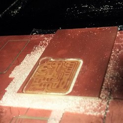
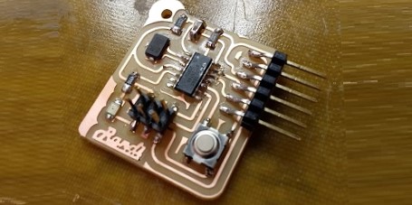
Step Two: Make
Hopefully by now you are an expert at milling and soldering boards. In milling, I advise you to be careful in the fab mods that the shape the computer thinks it is milling is the same one that you want it to mill. The colors and distances in the PNG files are very important. If things are too close to one another or the wrong color, then you will not have a good board. Take an extra second to check.