--How to Make (Almost) Anything--
--Week 09--
--Input Devices--
--Step 1: Designing the board in Eagle
For this week, I wanted to make some progress on my final project design, so my attempt was to create a board that has an accelerometer on it. This accelerometer will then be used to measure tilt, and the degree of tilt, either left or right, will then activate an LED on the associated side. For instance, if the degree of tilt is over 30 degrees to the right, then the LED designated the right hand side will blink rapidly for a few seconds. The same situation occurs for the LED designated left, when the tilt is over 30 degrees to the left.My final board design (a modification of the board design from the "embedded programming week") is as depicted in figure 1 below. One thing I had an issue with was routing all the traces on the board with only one side, so I made holes in the board to connect ground pins, either by using vias, or just using wires (wires for testing purposes, for now, in the interest of time).
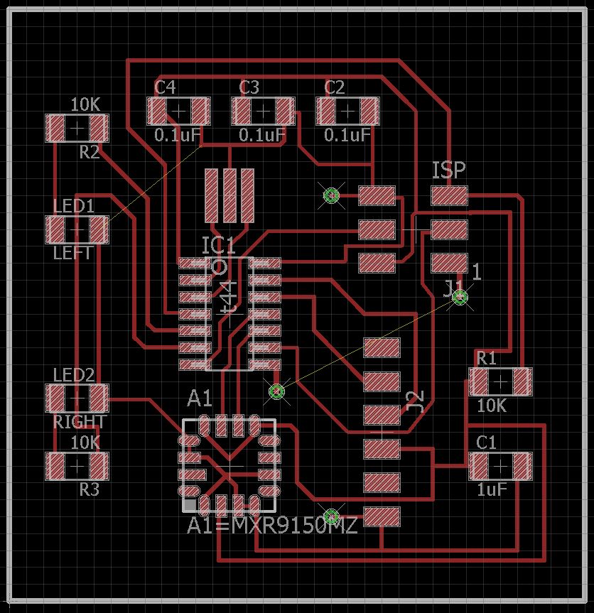
Figure 1: Final board design from eagle
I then proceeded to export my board design to a png format to be milled out on the SRM-20 milling machine ("electronics production week"). Figure 2 shows the exported png images.
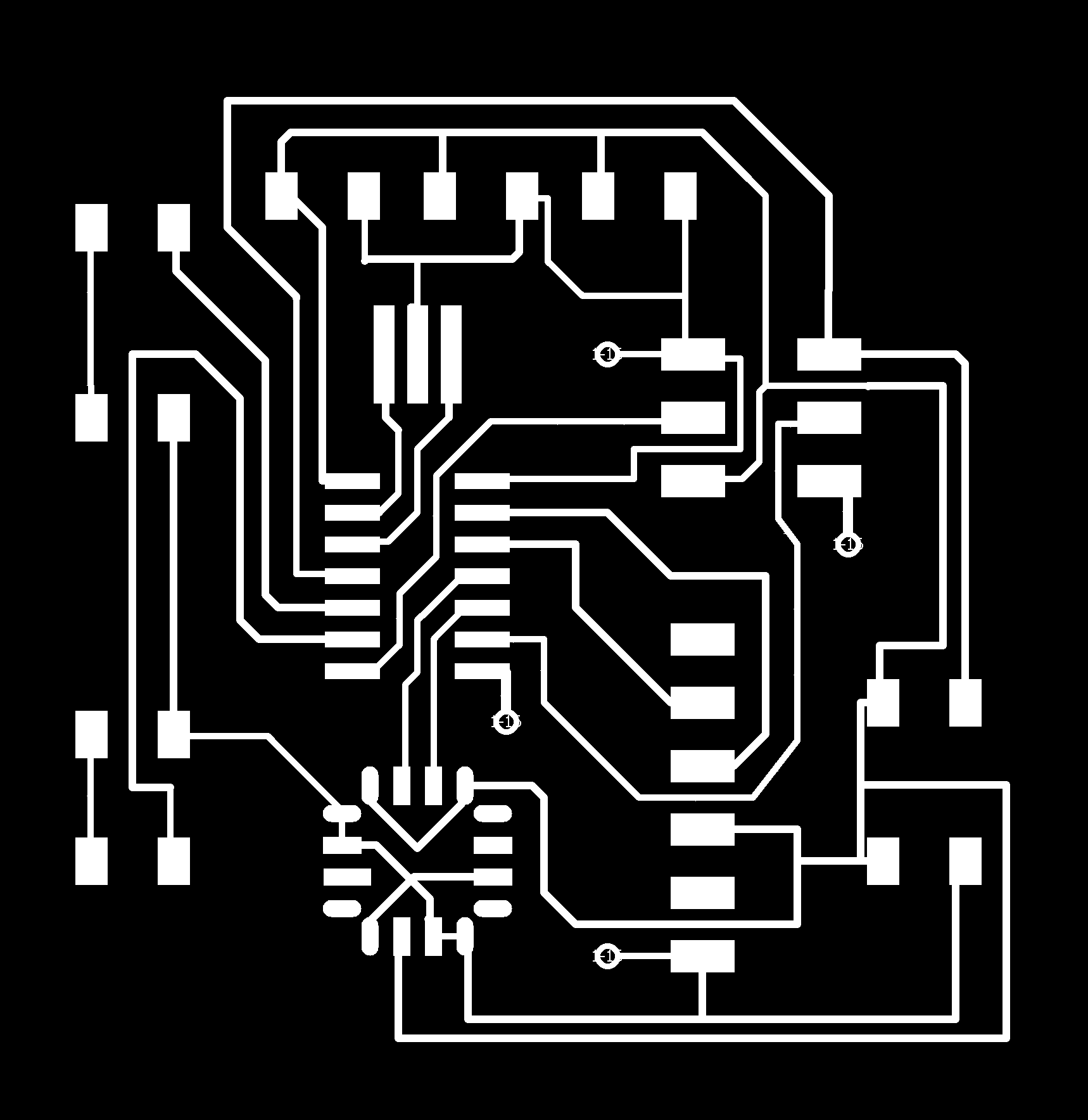
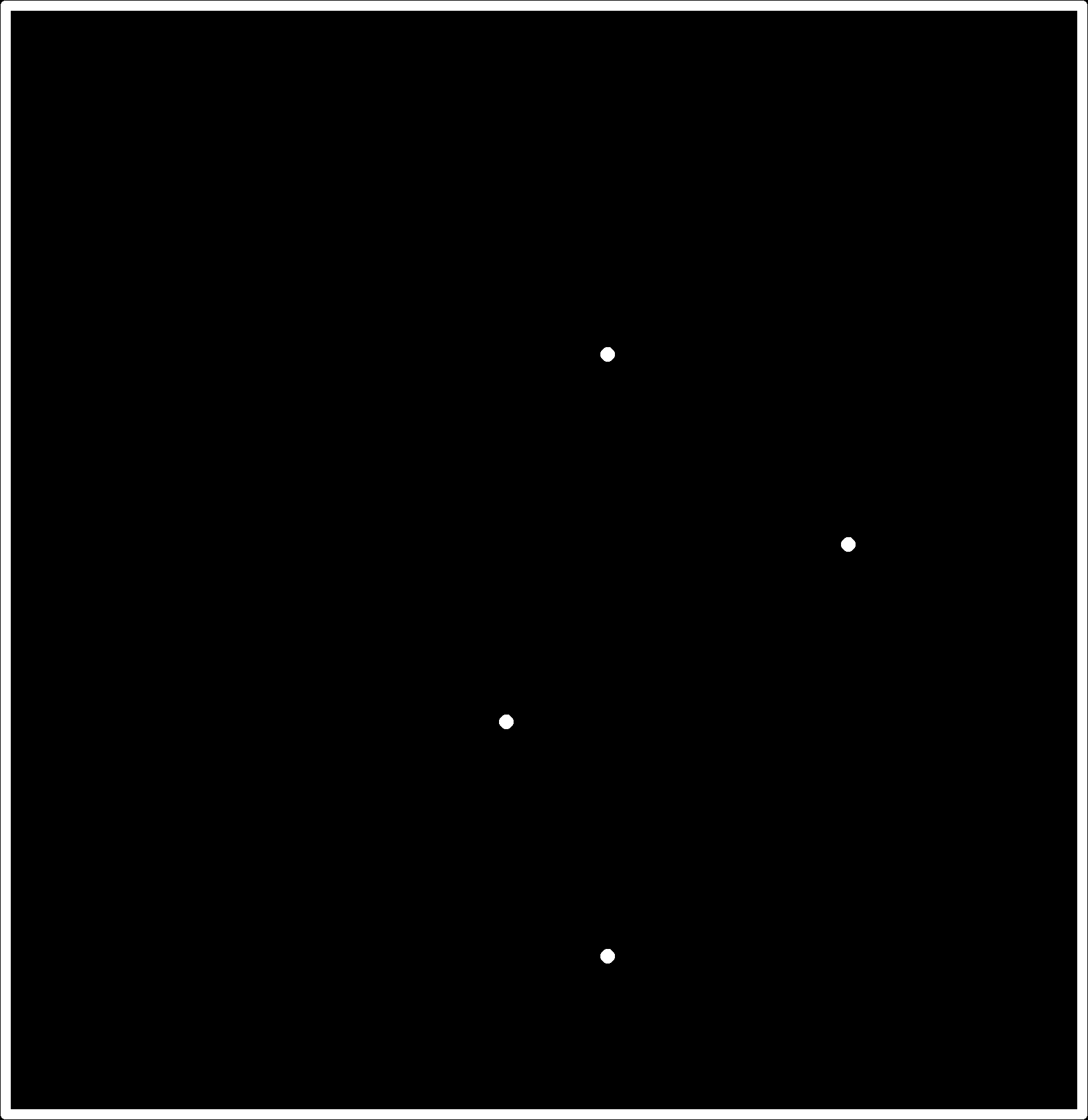
Figure 2: Exported PNG files (traces and interior)
--Step 2: Milling and stuffing the board
The milling process was pretty straightforward, and the final board is depicted in Figure 4. When it came to the stuffing process, I hit a major snag: As it seems to have turned out, the accelerometer listed on the fab.lbr for eagle is a completely different part from what is in the inventory, and stocked in the EECS lab. So I did not have the part I needed to finish the board stuffing. I ended up just putting the parts I did have on, with the hopes that I one of the other labs will have the part I needed (I sent out an email to this effect).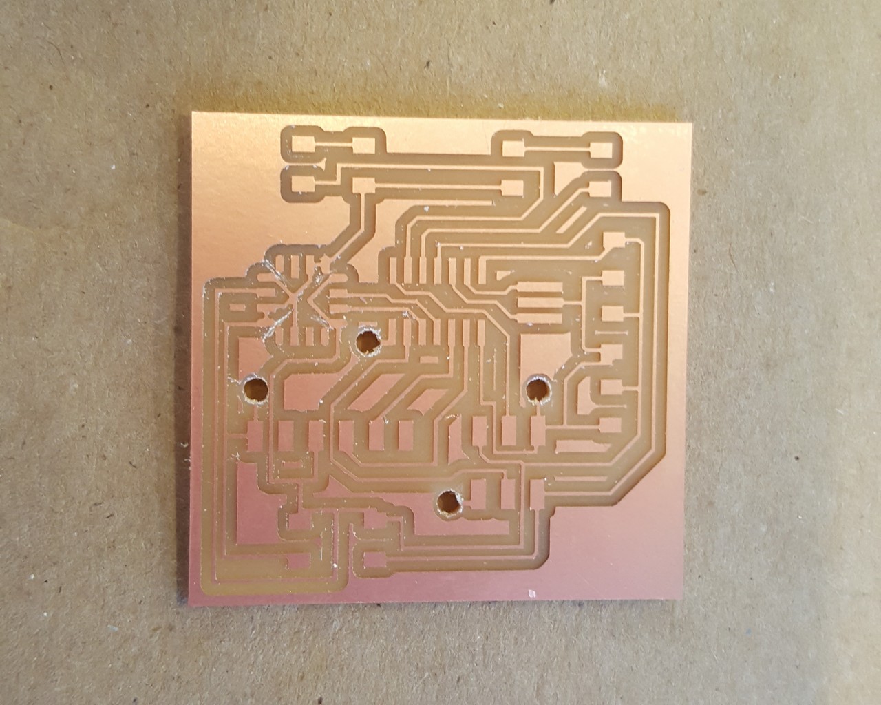
Figure 4: Milled Board
If this turns out not to be the case, it means that I would need to redesign my board with the part that we do have available in inventory. Figure 5 shows the board as it currently stands.
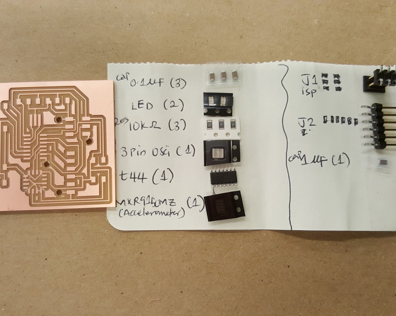
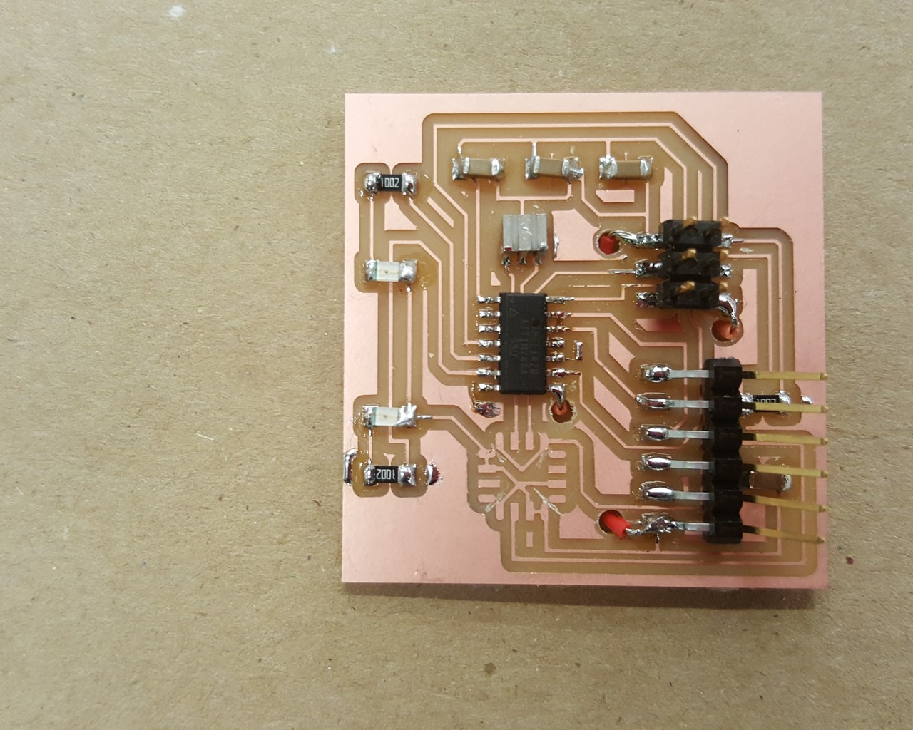
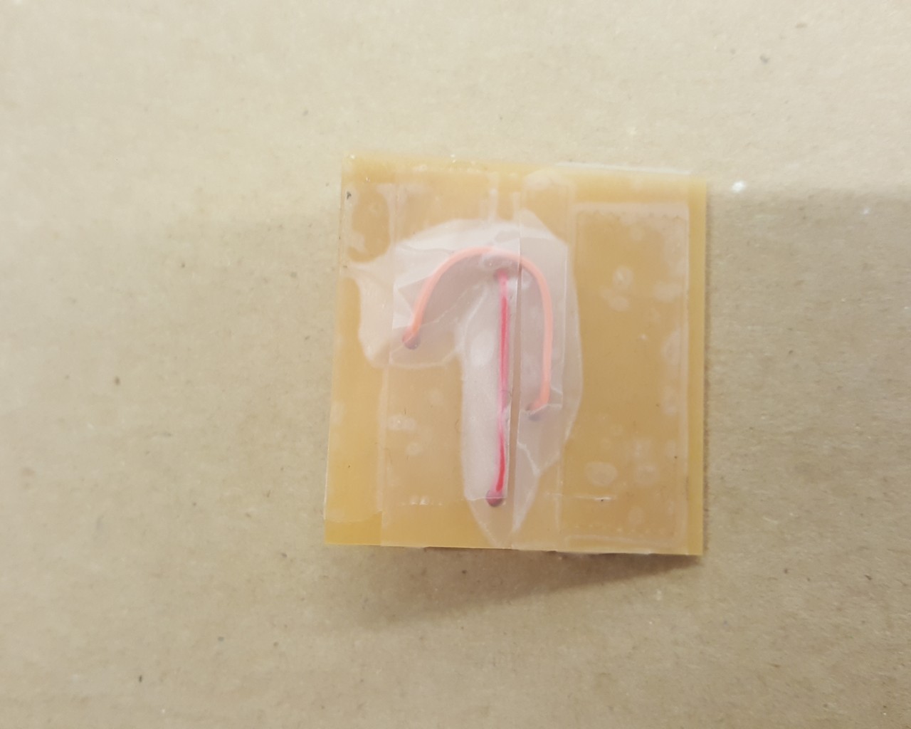
Figure 5: Final board design from eagle (top, and bottom makeshift GND connections)