Week 6: Computer Controlled Machining
19 Oct 2016 · 4 min readThis week’s assignment was to make something big using a CNC. We had a single piece of 4’ x 8’ x 7/16” oriented strand board (OSB) for us to use.
I decided to make something useful for my room. I do lots of outdoor activities, each requiring different types of shoes. My shoes were taking up too much floor space, so I decided to design a shoe rack. The first step was to measure the shoes I had so I could figure out appropriate dimensions for the shoe rack. I found that the largest shoes were around 12 inches long, 8 inches wide for the pair, and under 10 inches tall.
Sketches
After getting this information, I started making sketches on a piece of paper. I didn’t want to use wood glue or nails or screws, so I initially thought about making a simple press-fit design. I wasn’t sure how well press-fit would work with OSB without very high-precision cuts, so I decided to go with a different design that uses a peg, held in place by gravity, at a 90-degree angle to the joint:
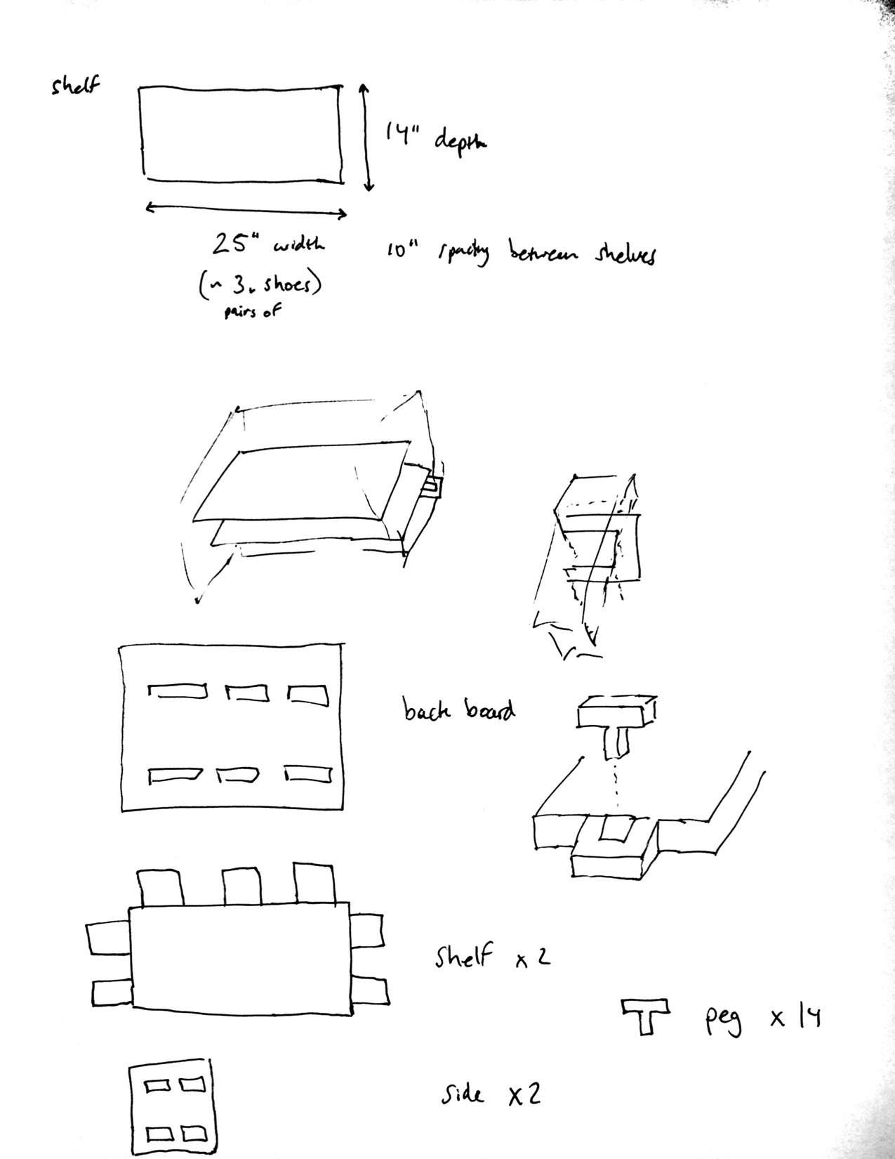
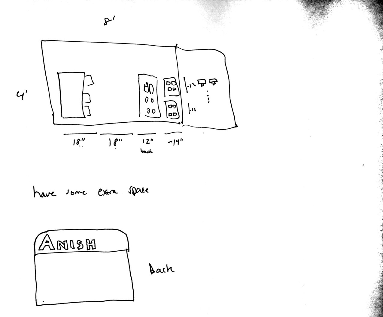
I made sure that everything would fit on my 4’ x 8’ OSB:
CAD
I decided to use Fusion 360 to design my shoe rack. I had used this software only once before while designing my press-fit kit, so I was looking forward to getting some more practice using the tool.
It took me about an hour and a half to complete a parametric design of the part:
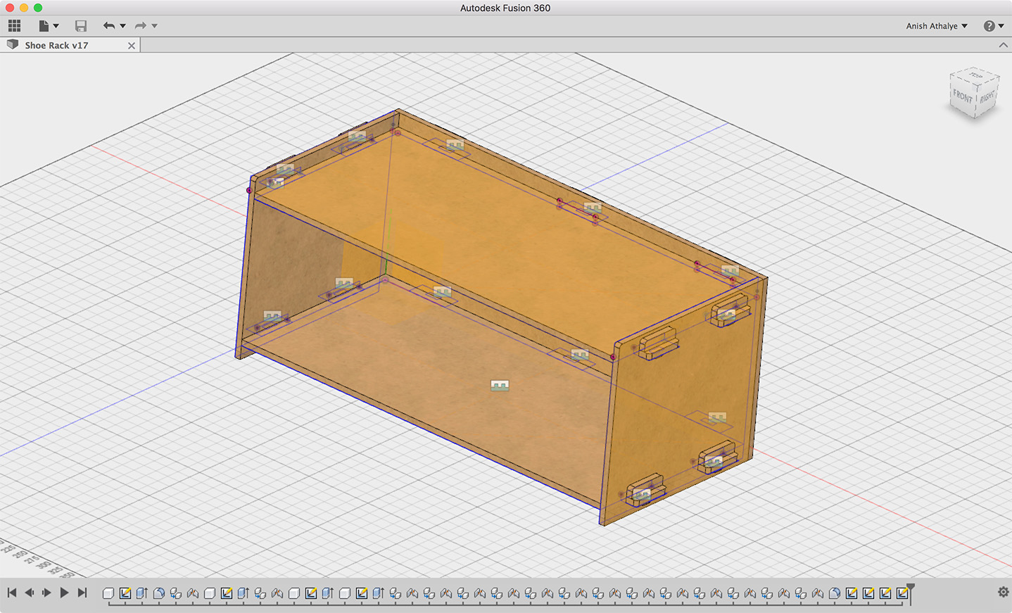
During the process of making the part, I made several mistakes that I had to go back and fix. One of the bigger mistakes was caught when checking for interference (overlapping volumes) — I found that my back panel was missing some cutouts because I had not selected all the holes when extruding the part. I fixed this using Fusion 360’s parametric timeline, which made the fix really easy; going through this process also helped me better understand how the parametric timeline works.
I decided to avoid engraving my name in the piece, because the inexpensive OSB didn’t seem to work very well for engraving in tests done earlier.
After completing my design, I noticed that I had a little extra space available on my piece of OSB, so I decided to change what I had in my sketches and change the width of the shoe rack from 25” to 30”. Thanks to the fully parametric design, this step took about 10 seconds.
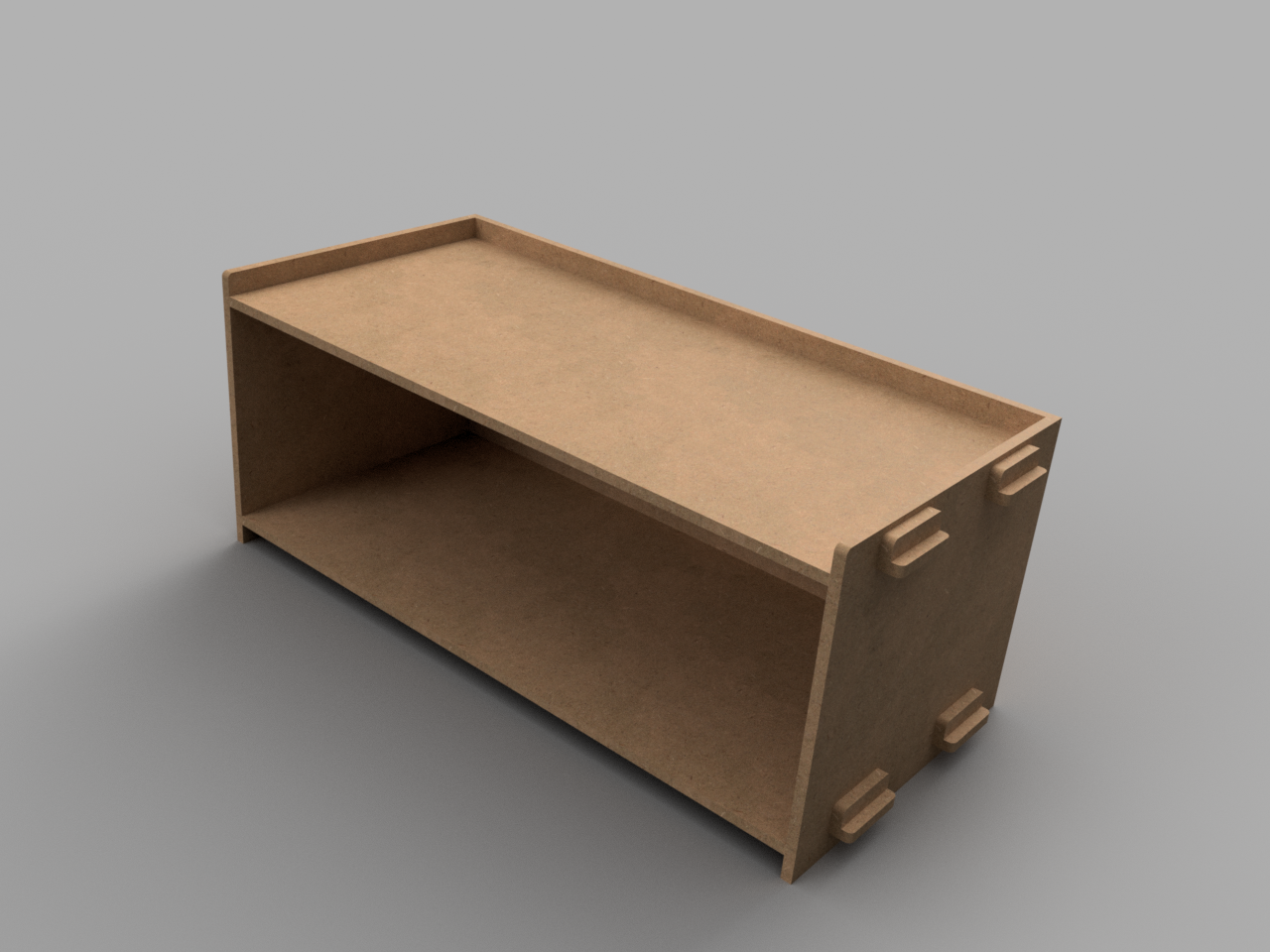
Here’s a render of the final version of the shoe rack:
Machining
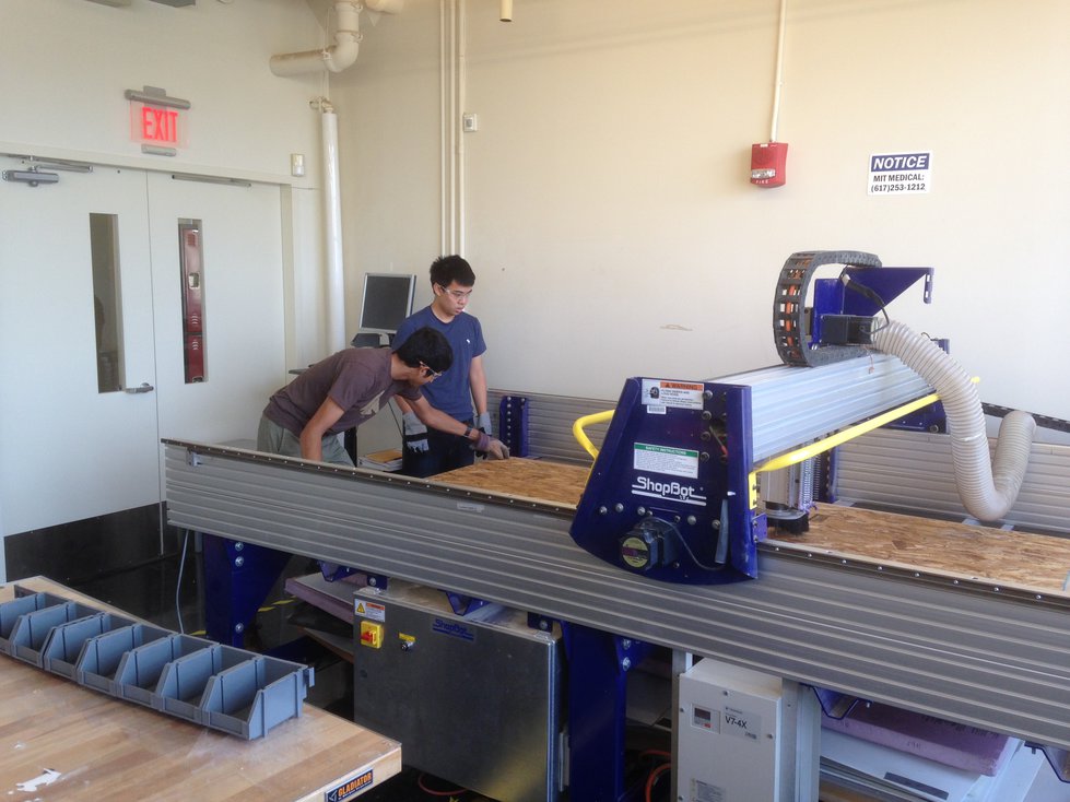
I used the ShopBot CNC router in the IDC to cut my piece. Here’s a picture of me and Kevin Kwok loading the 4’ x 8’ piece into the machine:
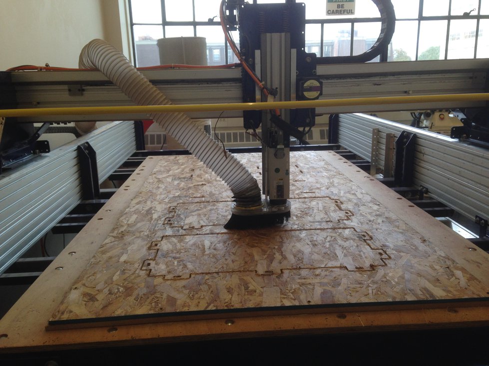
Creating the toolpaths was very straightforward — I cut out the holes first, and then I cut out the outlines. After creating the toolpaths, I zeroed the machine and started my job. Here’s a picture of the job in progress:
The entire job took about 21 minutes.
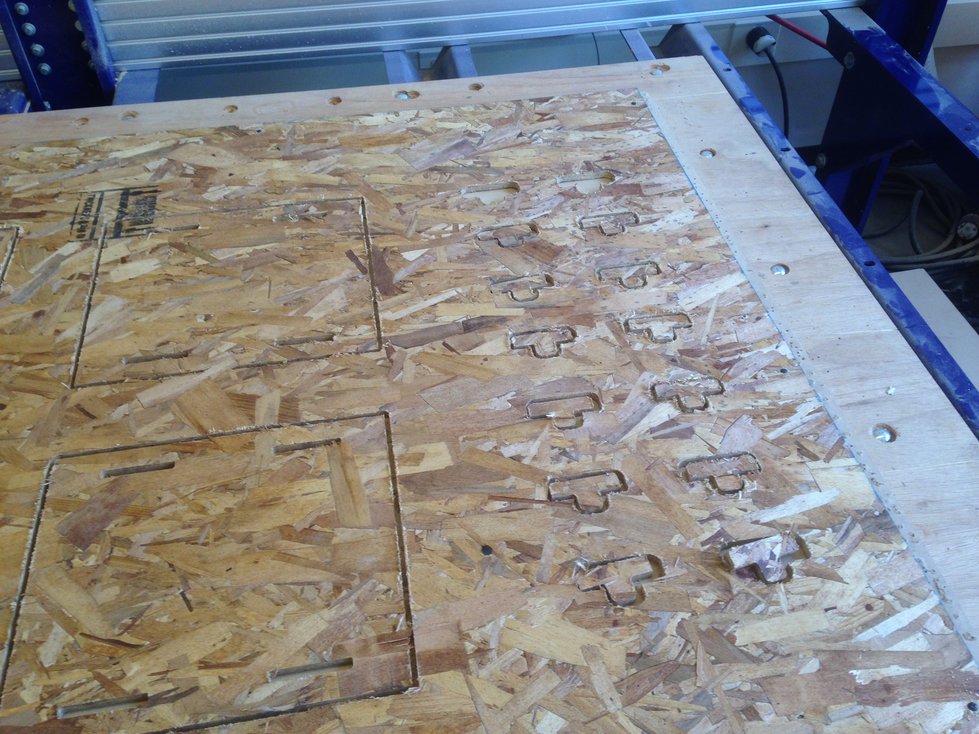
When cutting the small pegs, one of the pieces got sucked up by the vacuum attached to the end effector! I realized that this was because there was only a single tab connecting the piece to the rest of the board:
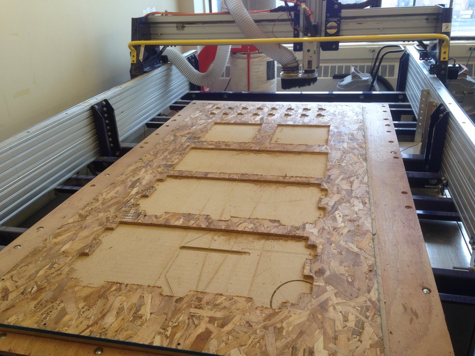
Luckily, this only happened to one piece. I recreated a toolpath for the lost piece, making sure to include a couple more tabs, and I machined a replacement. Here’s a picture of the board with all my pieces removed:
And here are all my parts:
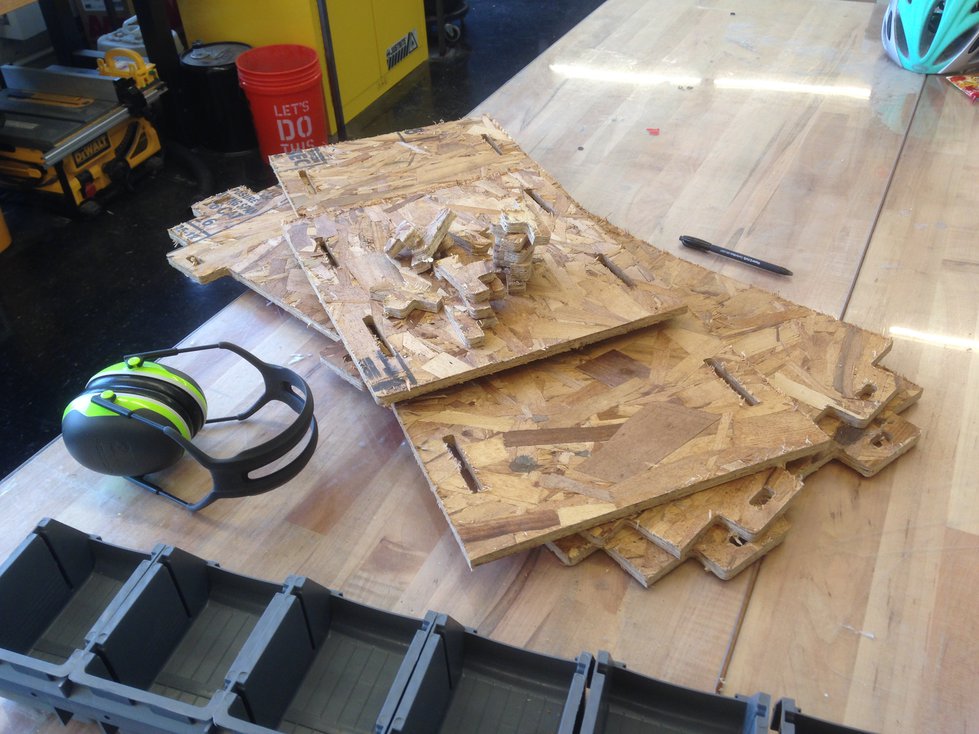
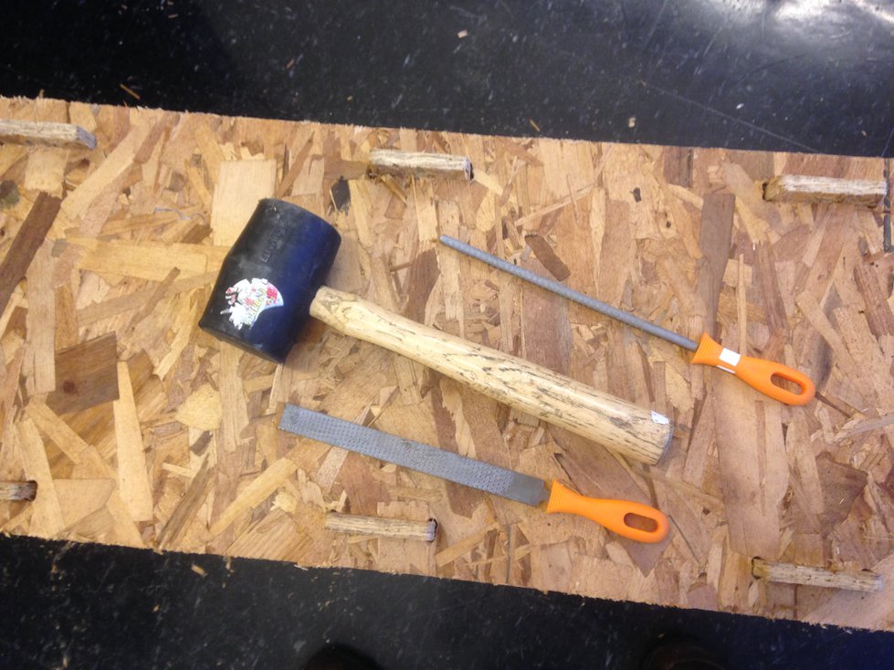
I realized that my parts didn’t fit together quite right. Making everything fit required some manual dogboning using a wood rasp and some hammering together with a mallet:
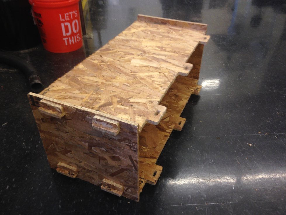
Here’s a shot of assembly in progress:
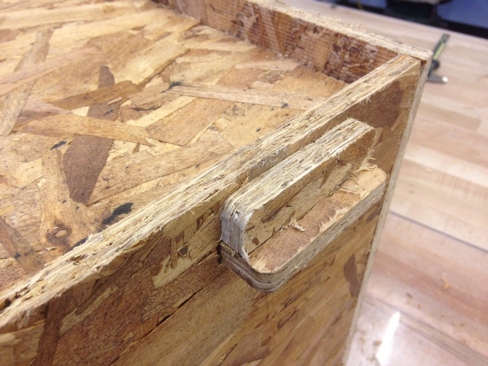
And here’s a close-up of a joint:
Result
Here’s the final result — a shoe rack, fully assembled:
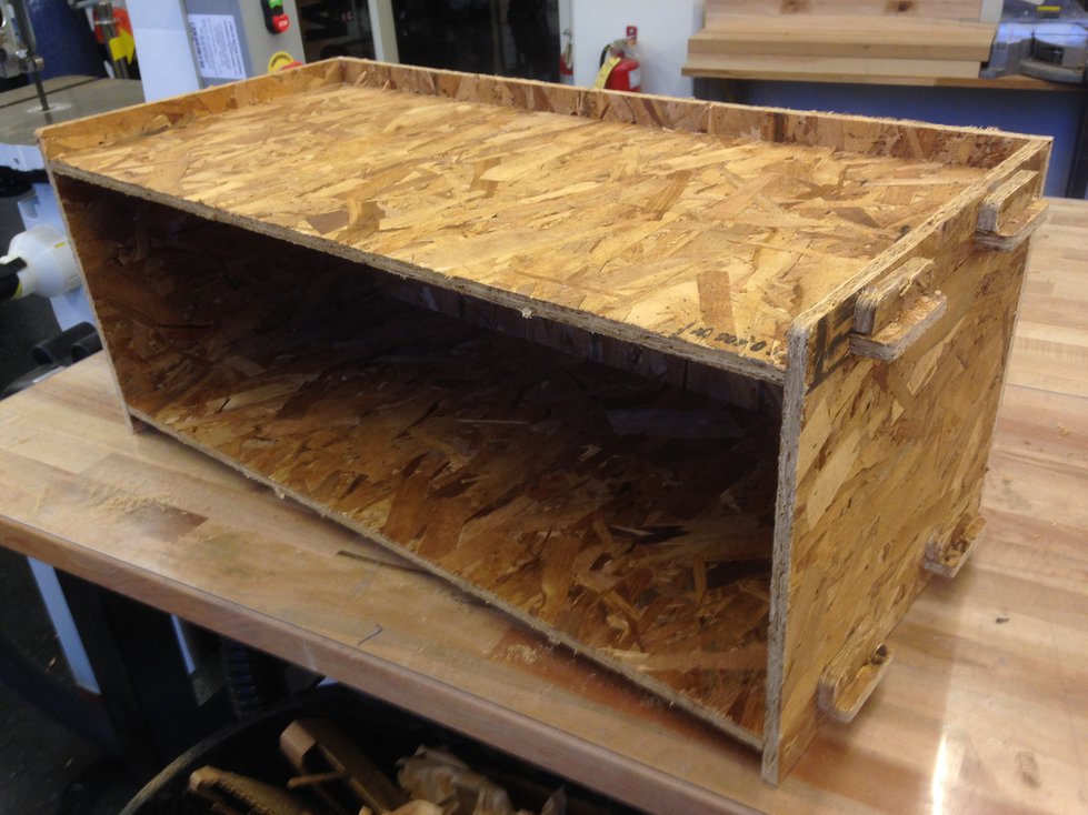
It turned out really well — everything fit very snugly — it didn’t wobble or anything. The whole project came together without using any wood screws, nails, or glue!