Project: μWWVB
Background
I built a watch stand that automatically sets my watch every night:
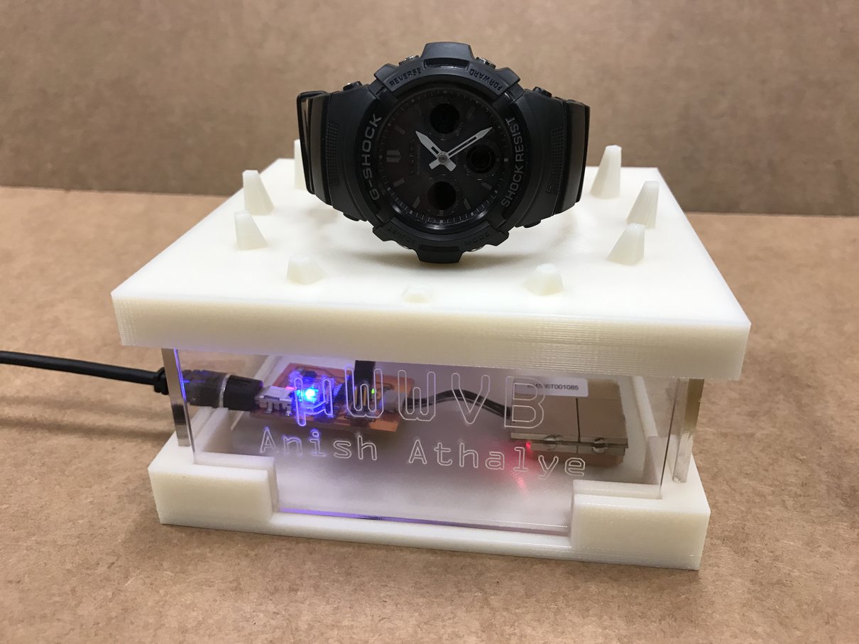
More specifically, I built a WWVB simulator so I can set my radio clock wristwatch even when I don’t receive the WWVB signal where I leave my wristwatch at night.
This post is written in the format of a build log. I’ve written another post on my main blog that has a little more background information and a more detailed description of the design process: www.anishathalye.com/2016/12/26/micro-wwvb/
Note: previously, I was planning on building an RC glider. To see my old project page, see here.
Radio Clocks
Radio clocks, sometimes referred to as atomic clocks, are clocks that get highly accurate time information from true atomic clocks that continually broadcast the current time over longwave radio. Radio clocks maintain time using quartz clocks and periodically synchronize with radio stations.
In the United States, the radio station WWVB, located in Fort Collins, Colorado, broadcasts time information on a 60 kHz carrier wave with a 70 kW ERP. Unfortunately, Massachusetts is pretty far away from Colorado, and so the signal in MA is pretty weak. As a result, my wristwatch syncs with the atomic clock in CO only about once a month.
Getting Accurate Time
In the absence of radio stations like WWVB which can provide time with an accuracy of about 100 microseconds, we can use other time sources. GPS can theoretically provide time with an accuracy of 10s of nanoseconds. The NTP protocol, which operates over the internet, can provide time with an accuracy of about 1 millisecond. Any of these time sources would be good enough for my use.
In the absence of synchronization with a properly calibrated clock, my watch’s clock can drift up to 15 seconds per month, according to the manual. This is typical for a quartz clock.
Legality
Building a WWVB simulator would involve transmitting on 60 kHz. In general, it is not legal to broadcast on arbitrary frequencies at arbitrary transmit power, because transmissions cause interference. Many parts of the radio spectrum are already in use, as allocated by the Federal Communications Commission (FCC).
Luckily, the FCC grants exemptions for certain unlicensed transmissions, as specified by the 47 CFR 15. This is explained in some detail in “Understanding the FCC Regulations for Low-Power Non-Licensed Transmitters”.
Transmissions in the 60 kHz band are allowed, and the emission limit at that frequency is given in 47 CFR 15.209. As long as I broadcast at under as measured at 300 meters, I should be fine.
In my use case, I’d be okay having the transmitter within a couple inches of the receiver in my wristwatch, so I wouldn’t need to transmit at a high power.
Part 1: Communicating to the Watch
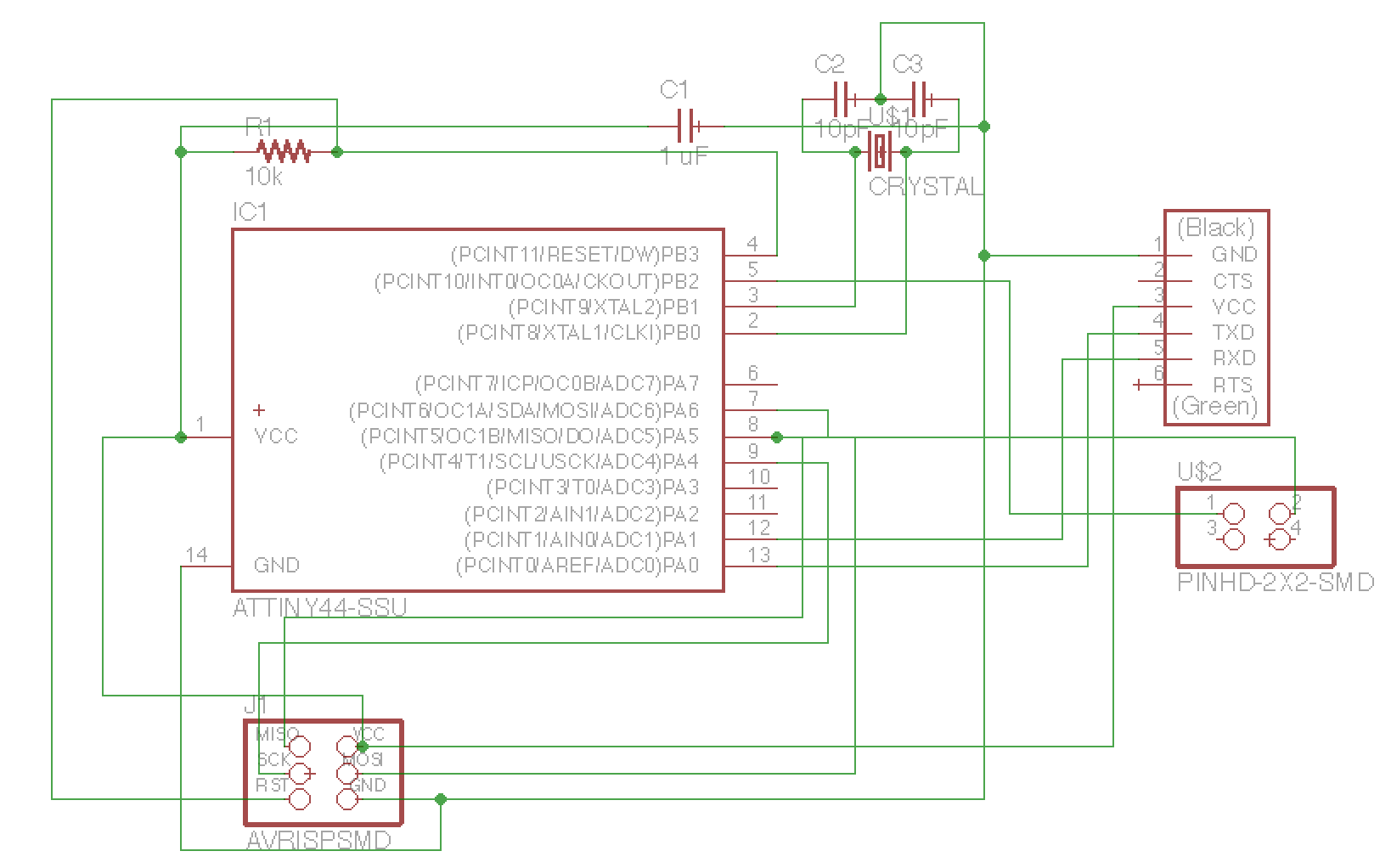
As a first step, I worked toward building a board to communicate with my watch to set it wirelessly. I designed a board with a pin header connected to a PWM output of the ATtiny44 so that I could send a 60 kHz simulated WWVB signal over the port to an antenna connected to the header.
Here’s the schematic:
And here’s the board:
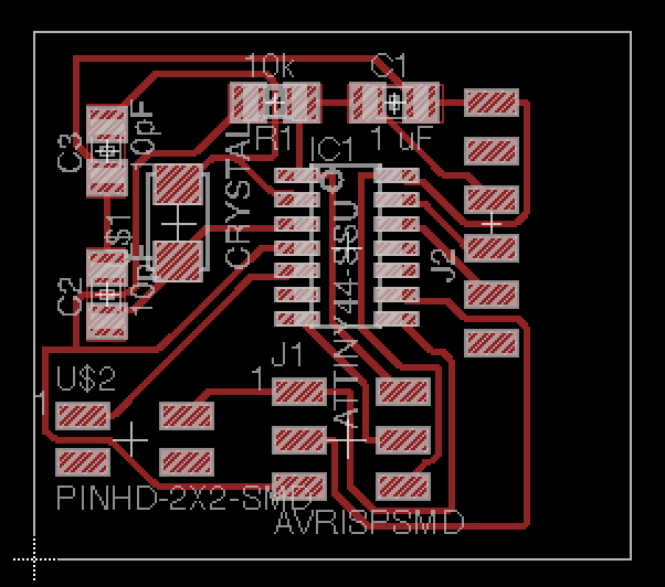
Here are the traces and outline.
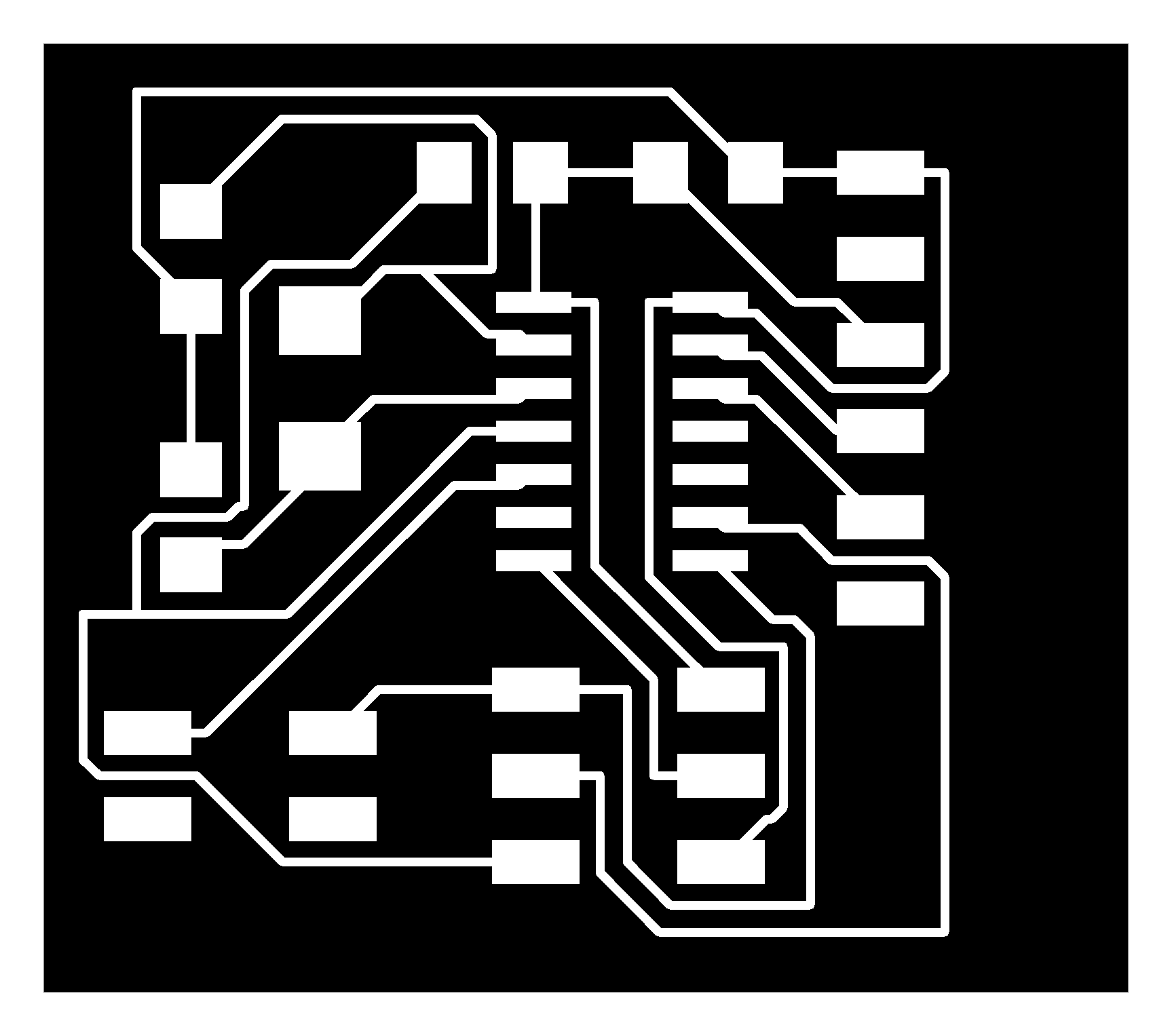
I milled the board on the Othermill using the Otherplan software. It worked really smoothly! Here’s the completed board:
I read the datasheet and set up the ATtiny44 to use one of its internal timers to do fast PWM to generate my signal:
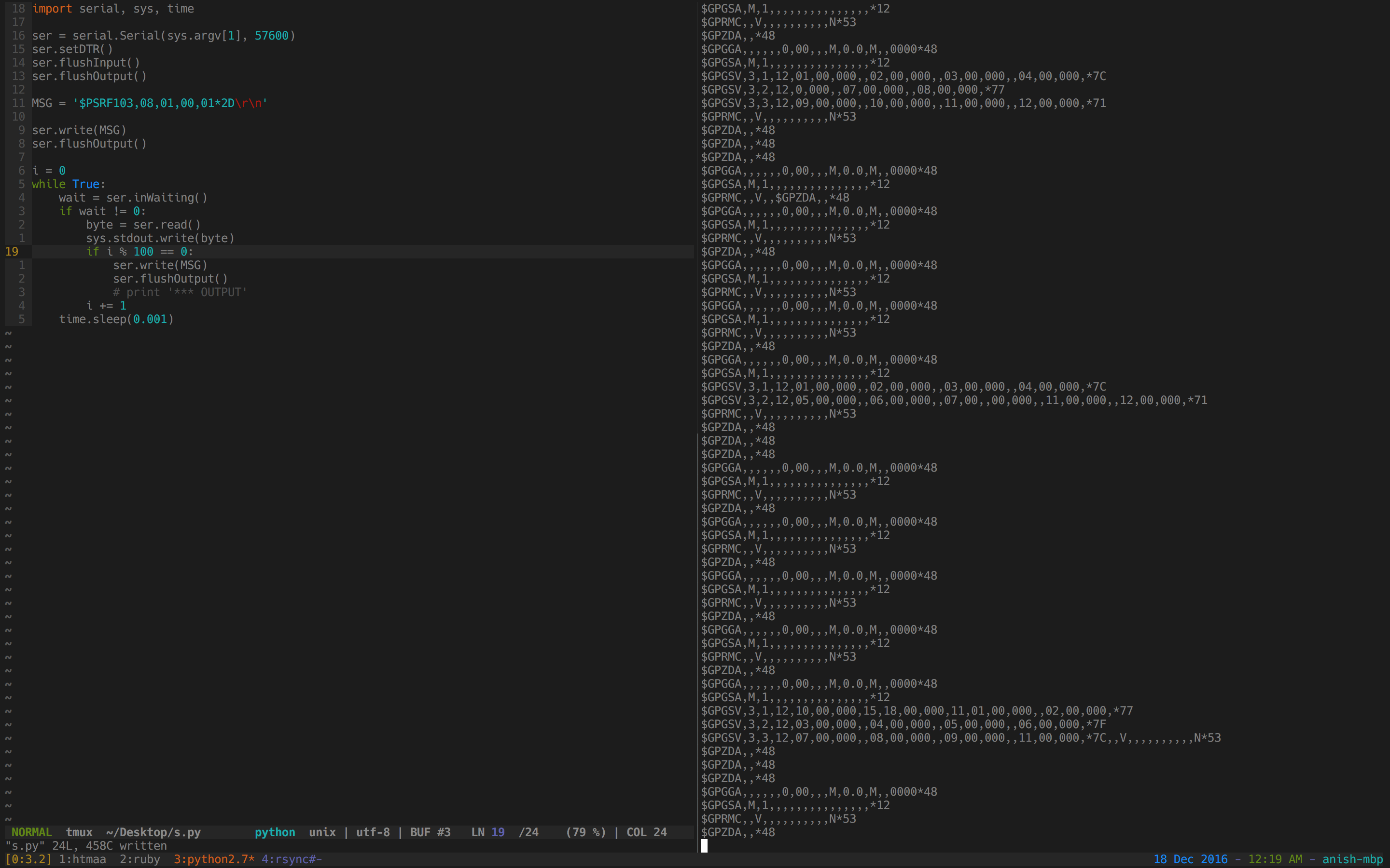
After that, I wrote some code to “fake” a WWVB signal (for some arbitrary date, rather than choosing the correct date). I tried using a random wire antenna to communicate with my watch, but it didn’t seem to work:
I was trying to send a 60 kHz signal, which has a wavelength of about 5000 meters — it’s hard to transmit that using a random wire antenna without a tuner.
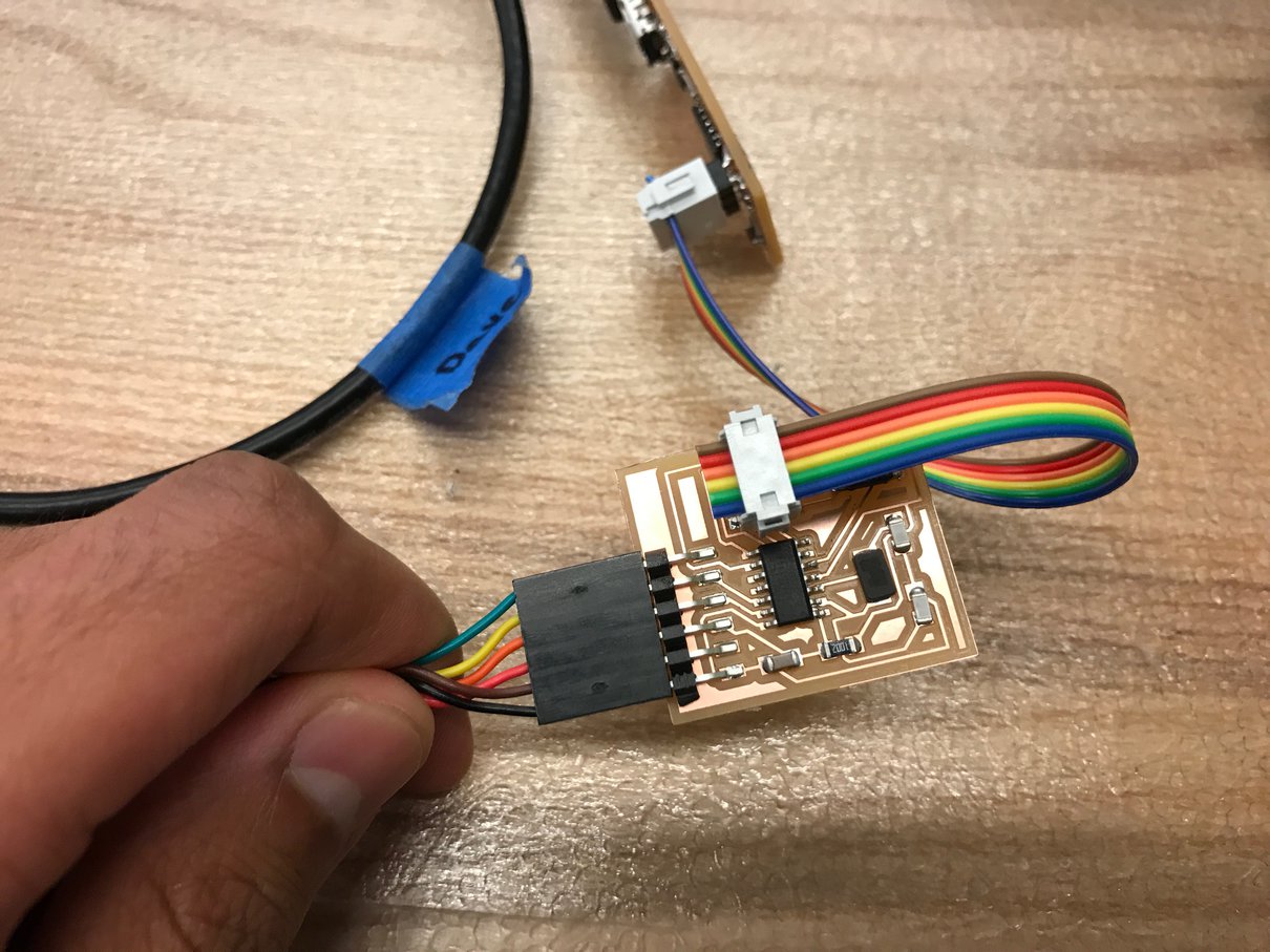
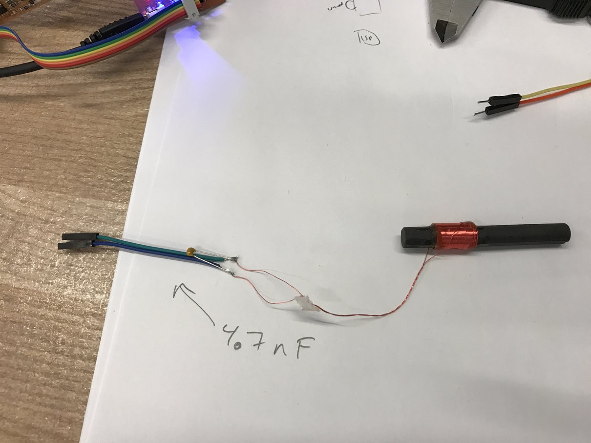
I decided to get a better antenna. I bought a Sterling and Noble 792684994149 Atomic Radio Clock and gutted it for its antenna (top left corner):
I took the antenna and resonated it using a 4.7 nF capacitor (according to this document).
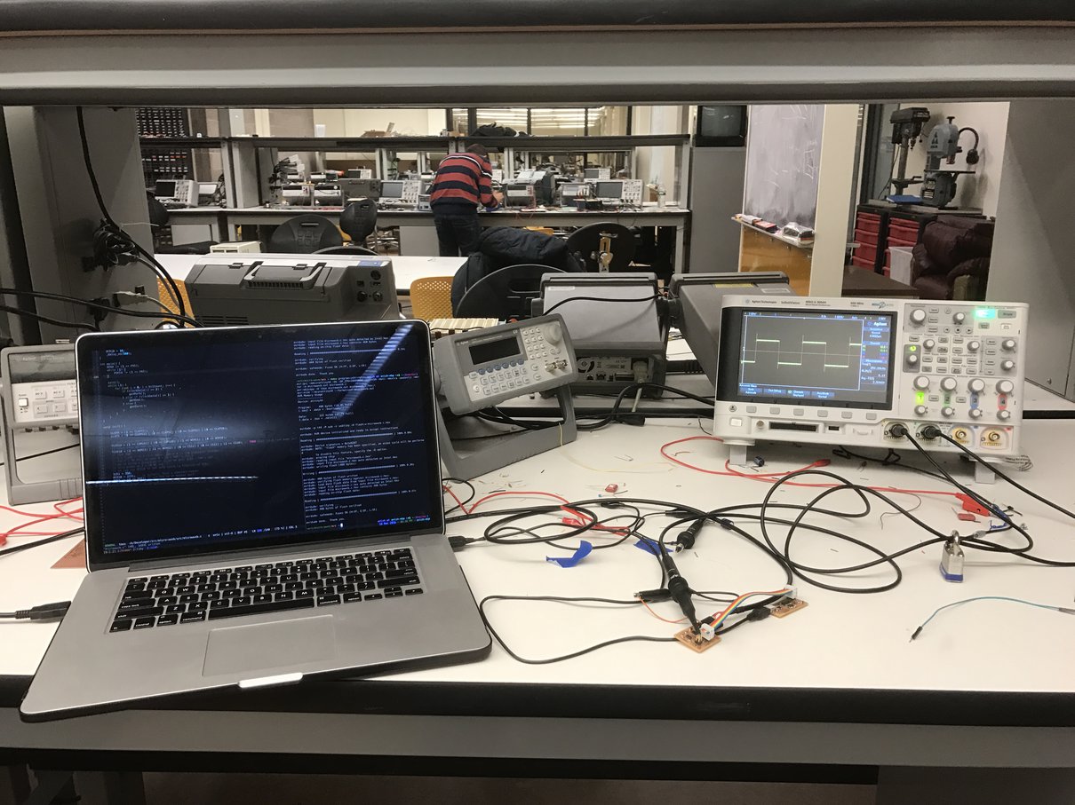
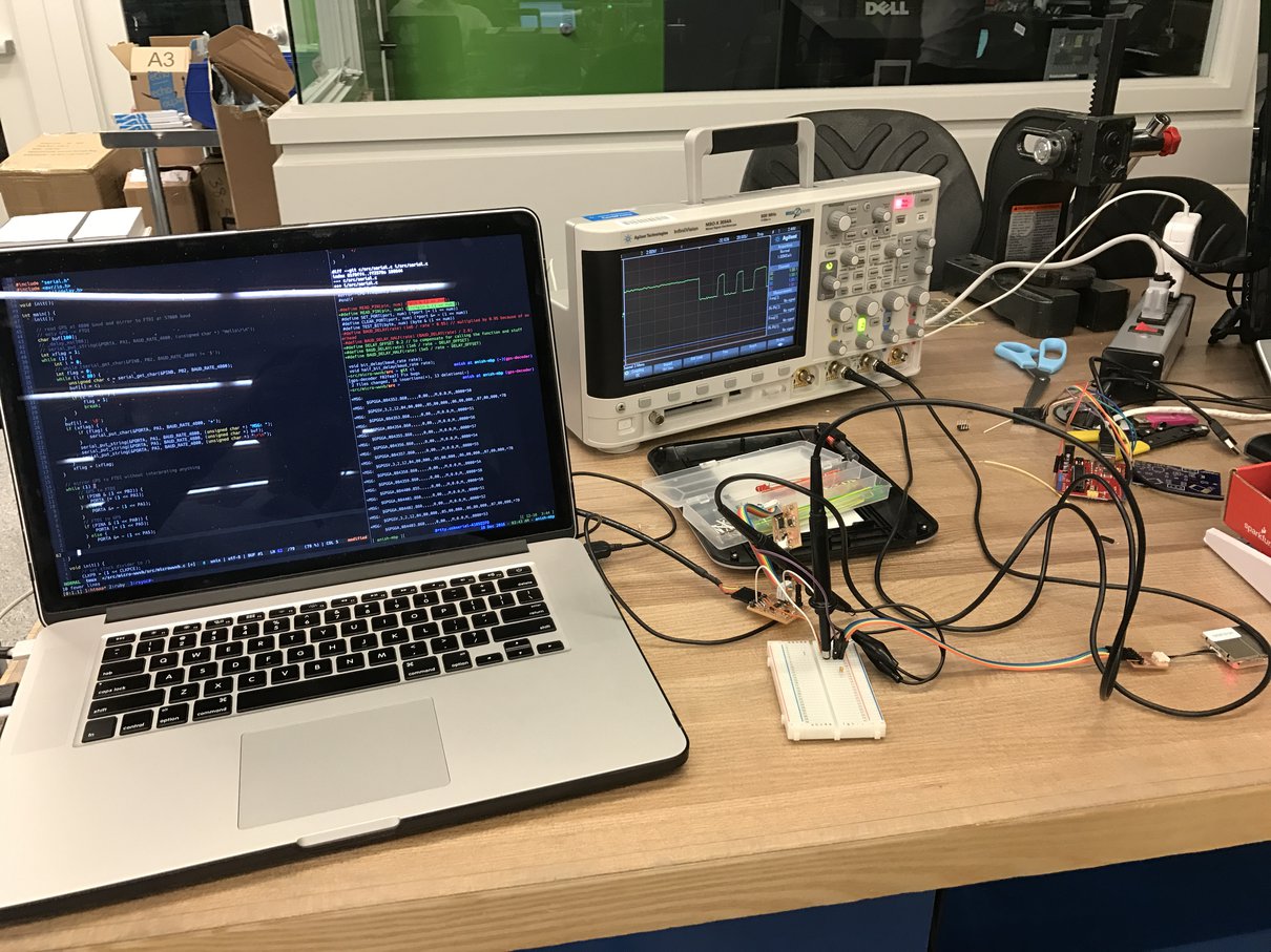
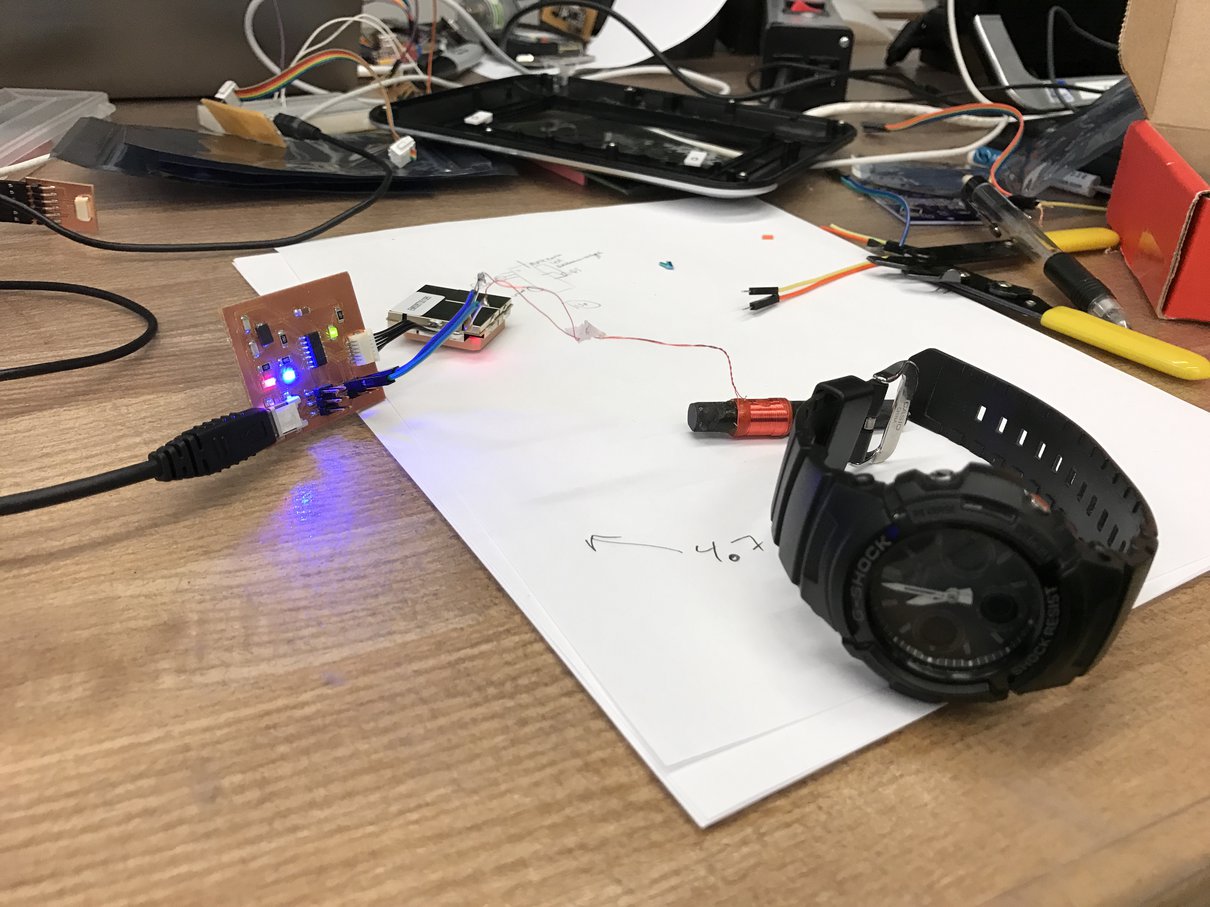
It took some debugging to get this working. I connected my board to a breadboard for easier reconfiguration, and I used an oscilloscope to try to figure out what was going wrong. In the image below, you can see the modulated WWVB output:
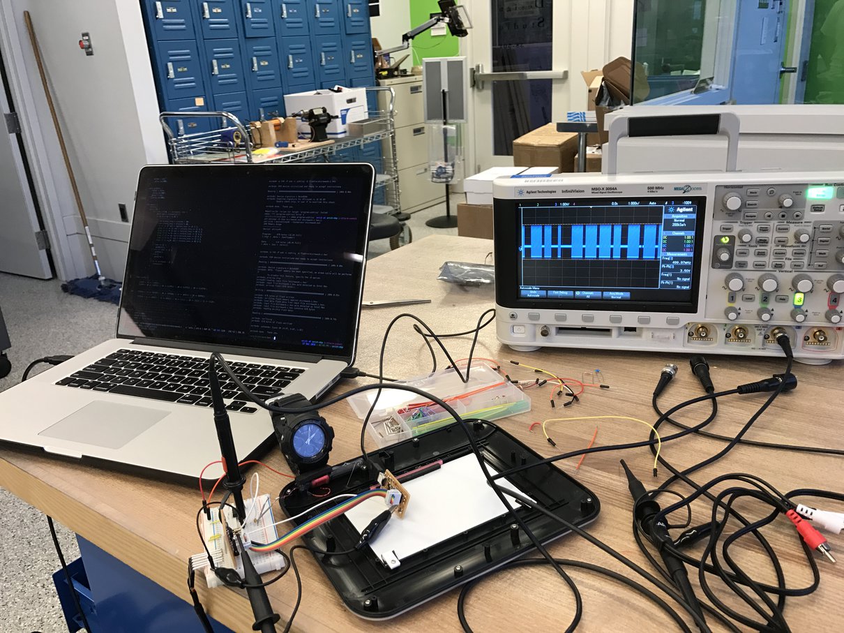
Eventually, after fixing various software bugs, I was able to get my board to communicate with my watch!
Part 2: Getting the Time
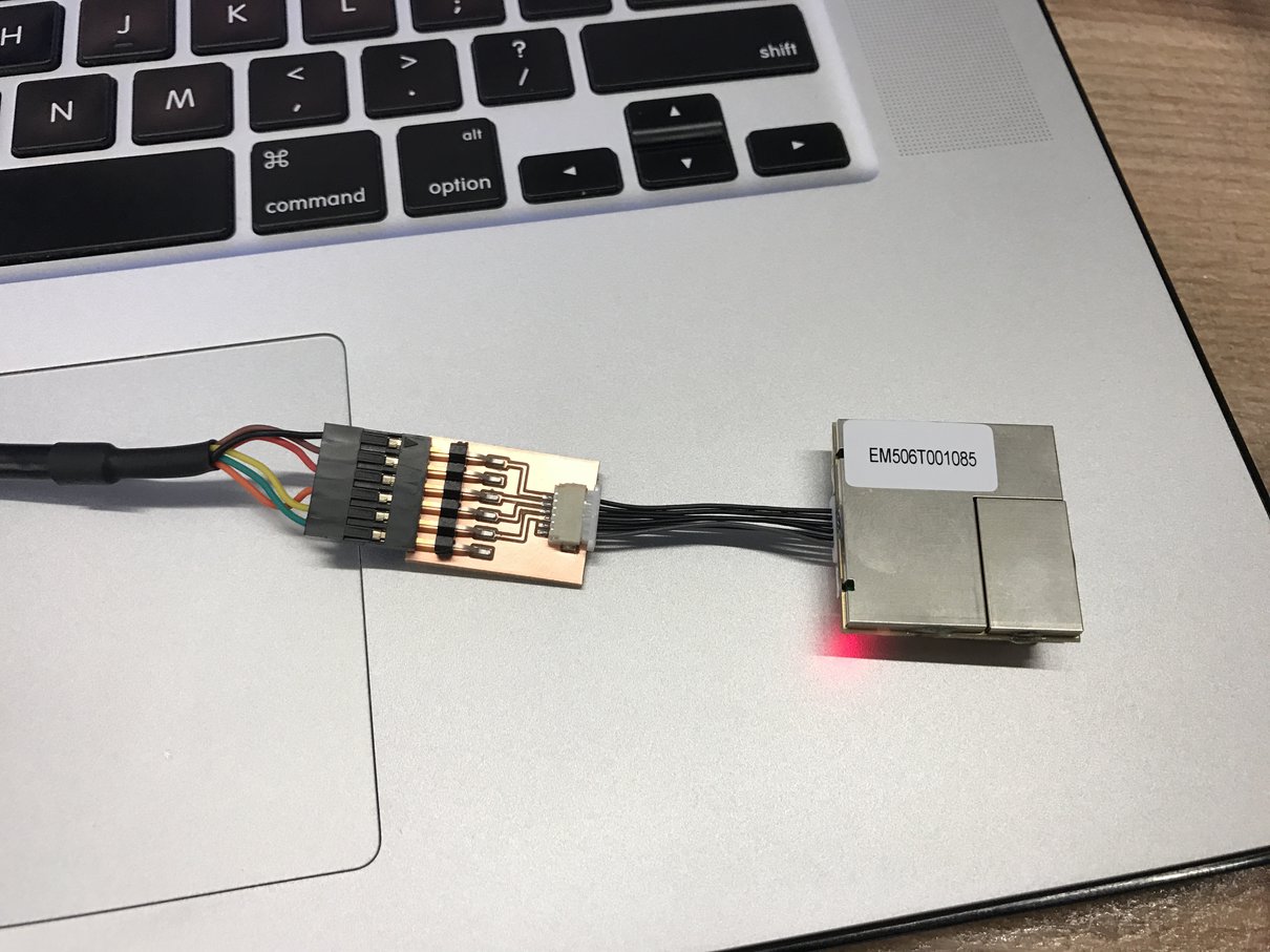
Next, I needed a way to get the time. I decided to use GPS, so that I wouldn’t need to be connected to the internet for my watch stand to work. I got a EM-506 GPS receiver from SparkFun. This GPS is powered by a SiRFStar IV chip, and it can communicate over NMEA.
After reading the datasheet, I built a simple board to interface the GPS with an FTDI connector so I could communicate directly with the GPS from my computer. This was so I could familiarize myself with NMEA before trying to get a microcontroller to directly interface with the GPS.
I used a JST horizontal 6-Pin connector to connect to the GPS cable. Here is my board (traces and outline):
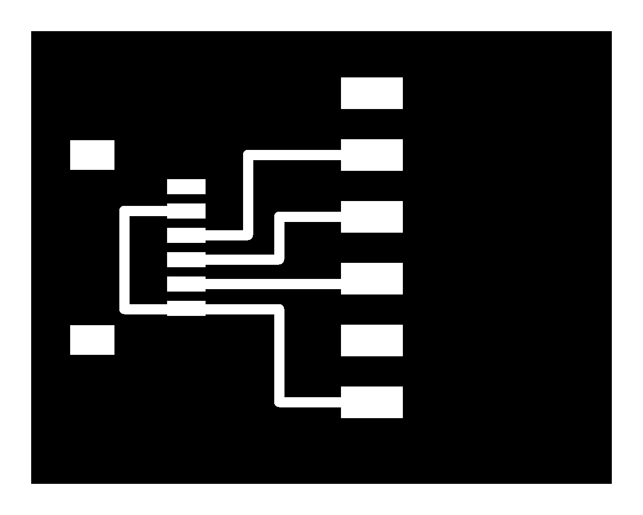
NMEA is an ASCII-based protocol that runs over UART, so I was able to use GNU screen’s serial support to communicate with my GPS.
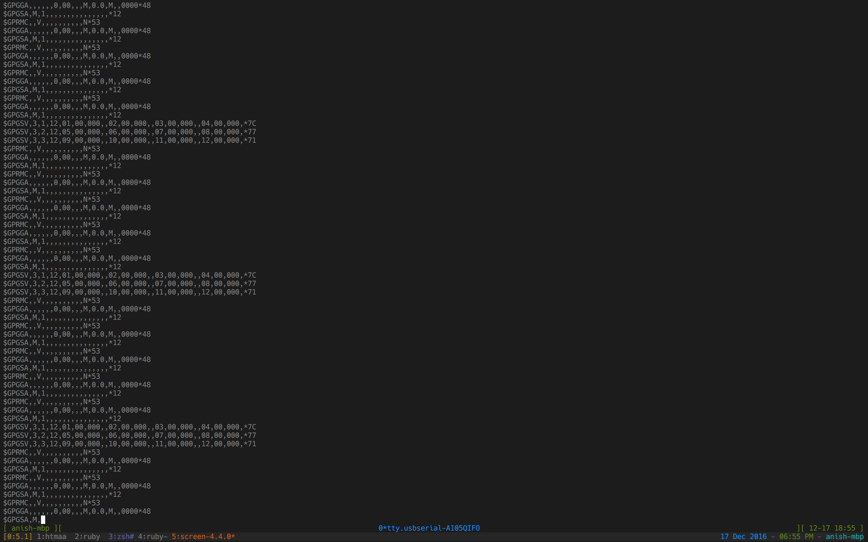
After reading SiRF’s NMEA reference
manual,
I was able to find the command to send to the GPS to request the current time:
$PSRF103,08,01,00,01,*2D\r\n:
Next, I needed to figure out how to interface the GPS with a ATtiny44 and parse the current time from it. Instead of making a new board for this purpose, I repurposed my board from Part 1, using a breadboard and my FTDI breakout to connect everything together:
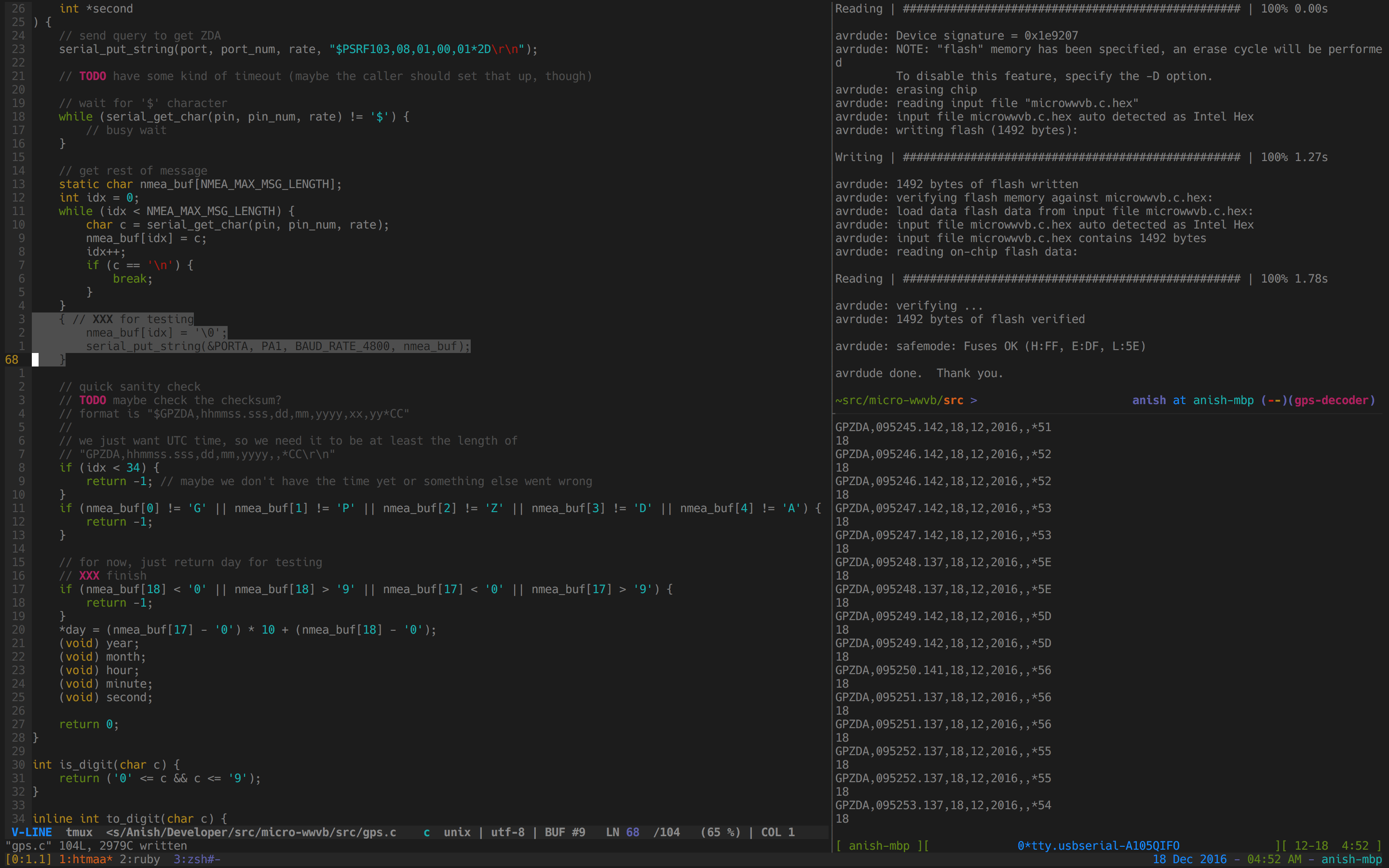
I wrote some code to talk to the GPS at 4800 baud and parse the date. Here is an intermediate result of parsing the current day of month:
Finally, I wrote some date/time utility code to do date conversions and things like leap year calculation.
Part 3: Broadcasting GPS Time via WWVB
Next, I needed to put Parts 1 and 2 together, making a single board read data from GPS and rebroadcast the time via WWVB. This was my final board.
First, I prepared my antenna to be connected to pin headers:
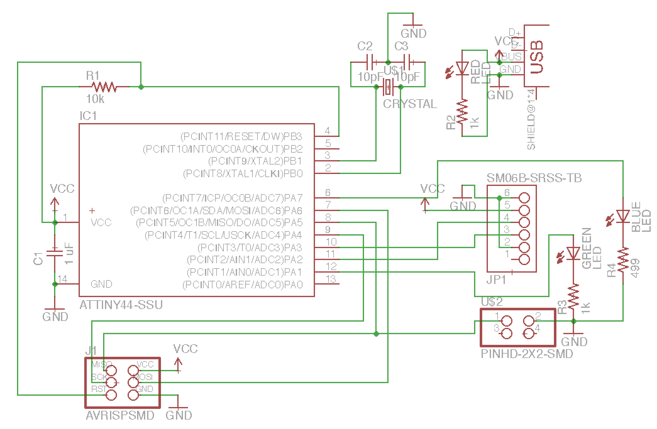
I made a schematic for a board with:
- ATtiny44
- 20 MHz crystal clock for accurate time
- USB power for ease of use
- 3 LEDs (1 red, 1 green, 1 blue) for status information
- AVR ISP headers
- antenna pin headers
- JST-SH 6 pin connector for GPS
All of the parts for this system, except the JST-SH connector, GPS, and WWVB antenna came from the fab lab inventory. The system costs about $50 in parts (the bulk of the cost comes from the GPS and WWVB antenna).
Here is the schematic:
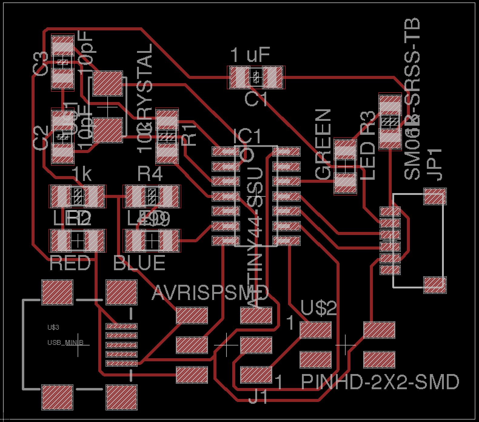
And here is the board layout:
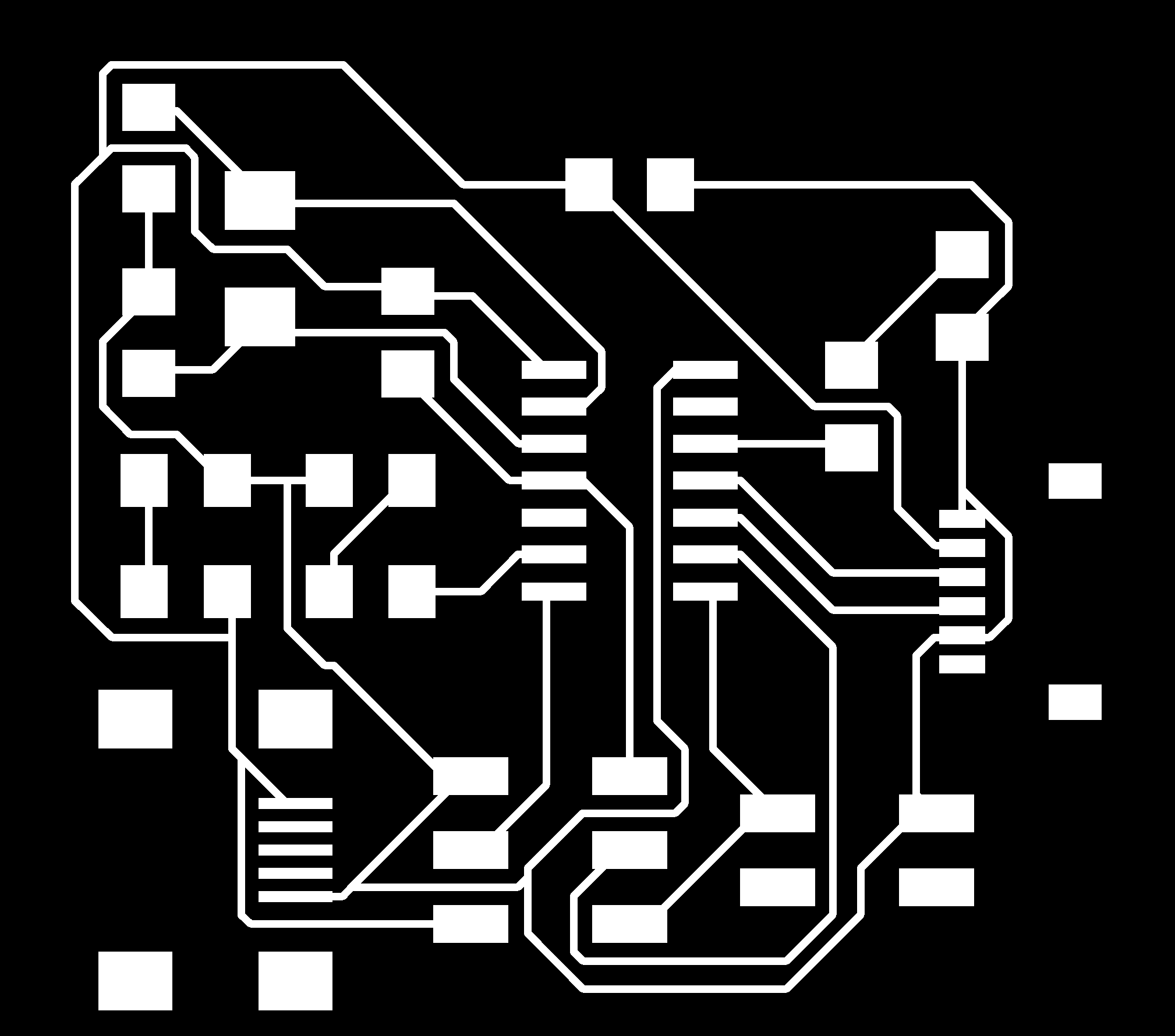
And here are the traces:
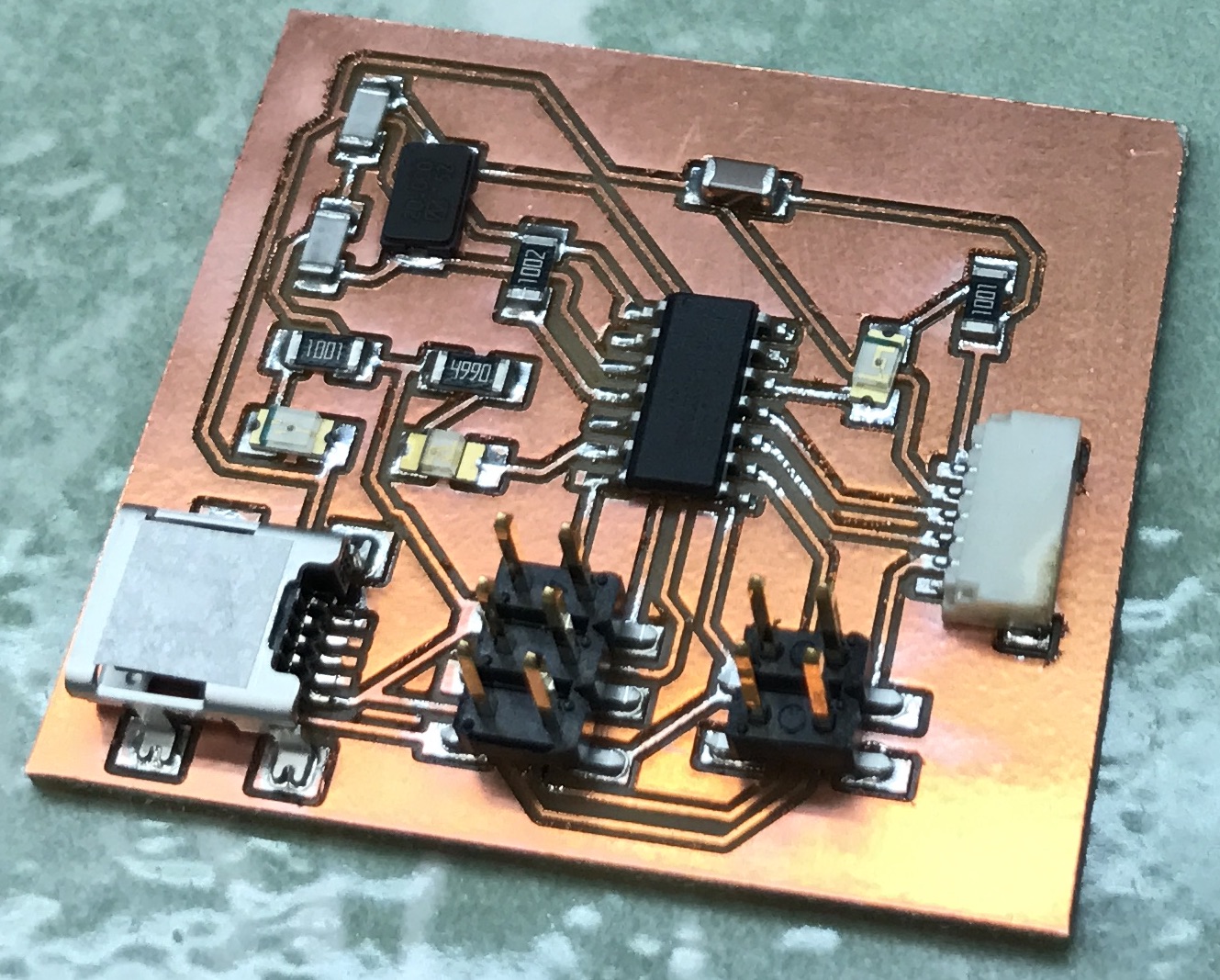
Here’s the completed board:
Writing the software for this was pretty straightforward: I basically combined what I wrote for Part 1 and Part 2 and everything worked!
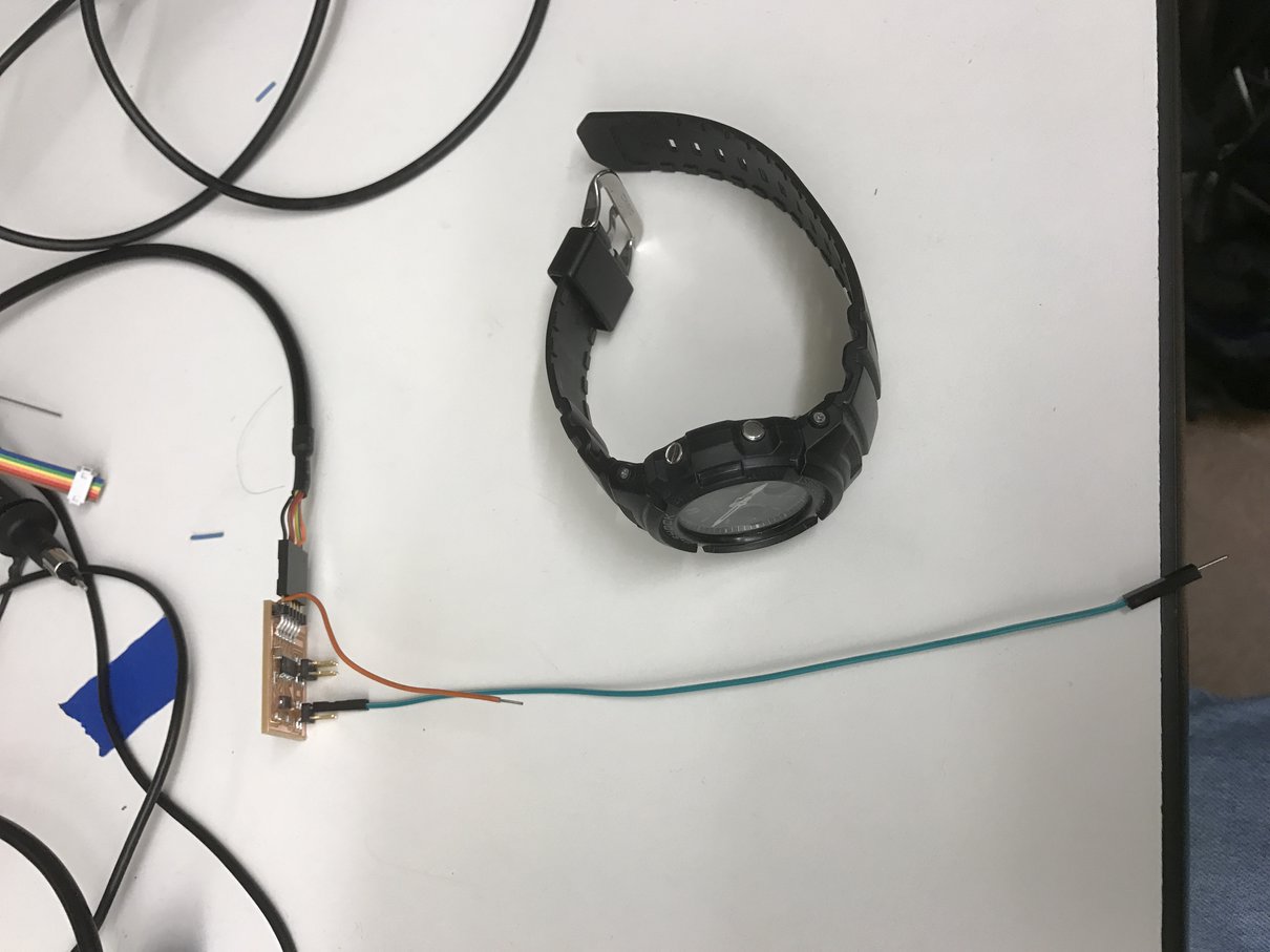
Here’s a picture of me syncing my wristwatch using the system:
I set up LEDs so that red indicates power to the board, green indicates GPS fix (that the board has the correct time), and blue represents the unmodulated WWVB signal.
Electrically, the entire system worked! All I had left was to build the physical watch stand.
Part 4: Watch Stand
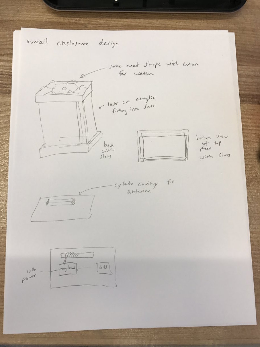
First, I sketched out some possible designs for a watch stand, intended to be made with 3D-printed plastic plus laser-cut acrylic:
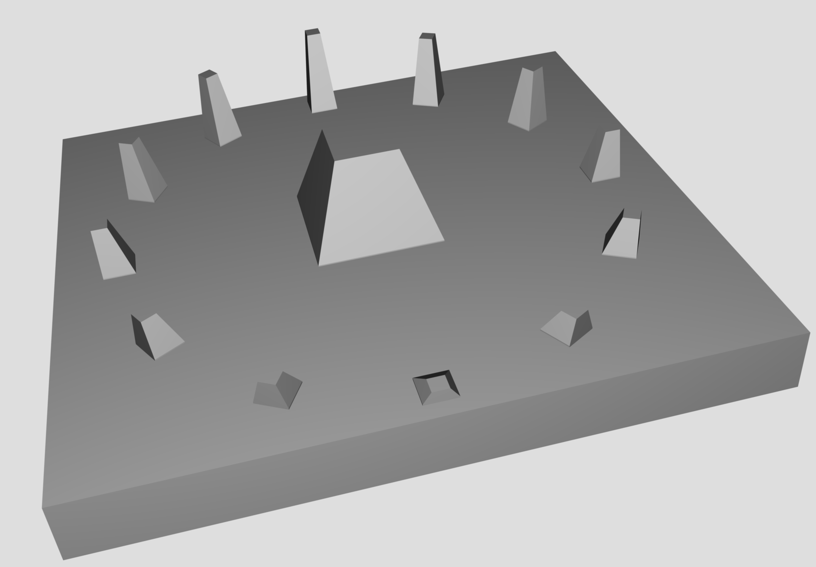
I used OpenSCAD to design my 3D-printed parts. Here’s the top:
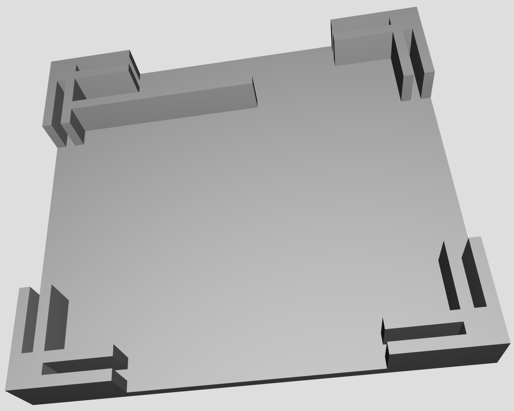
And here’s the bottom:
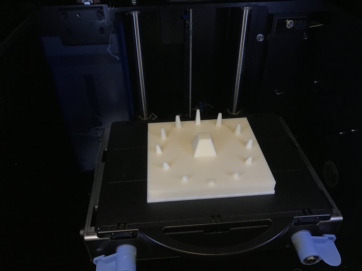
Here’s the result of 3D-printing the top on the Stratasys uPrint SE:
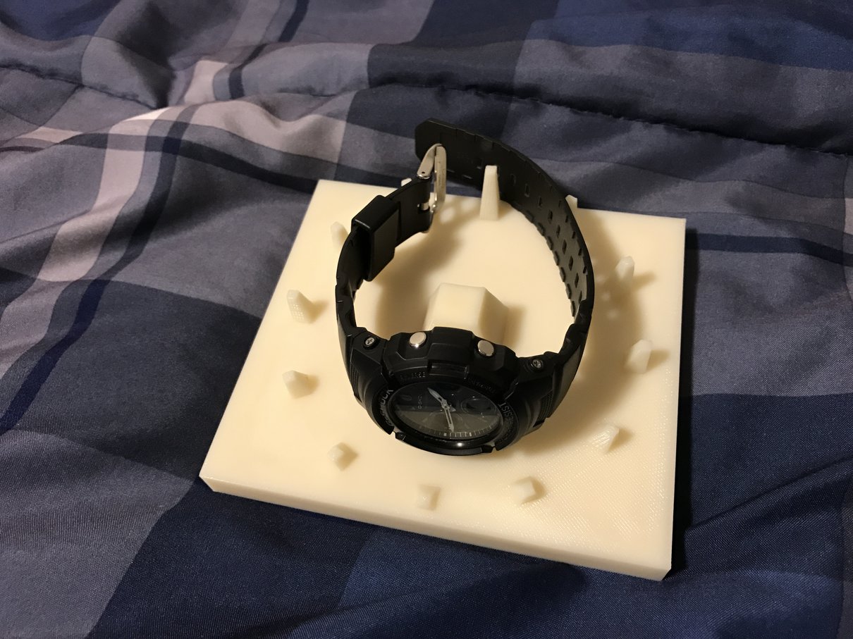
With my watch on it:
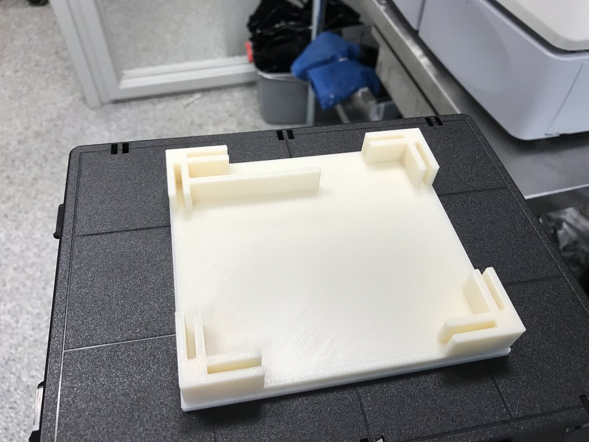
Here’s the printed bottom:
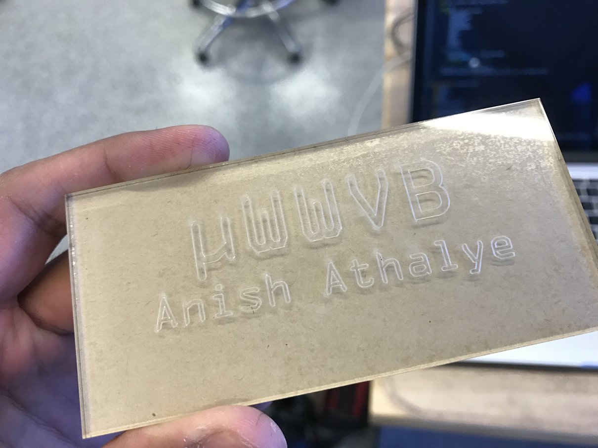
Next, I designed the side walls in Illustrator. Here’s the front:

And here’s the left:

It cut pretty nicely:
Result
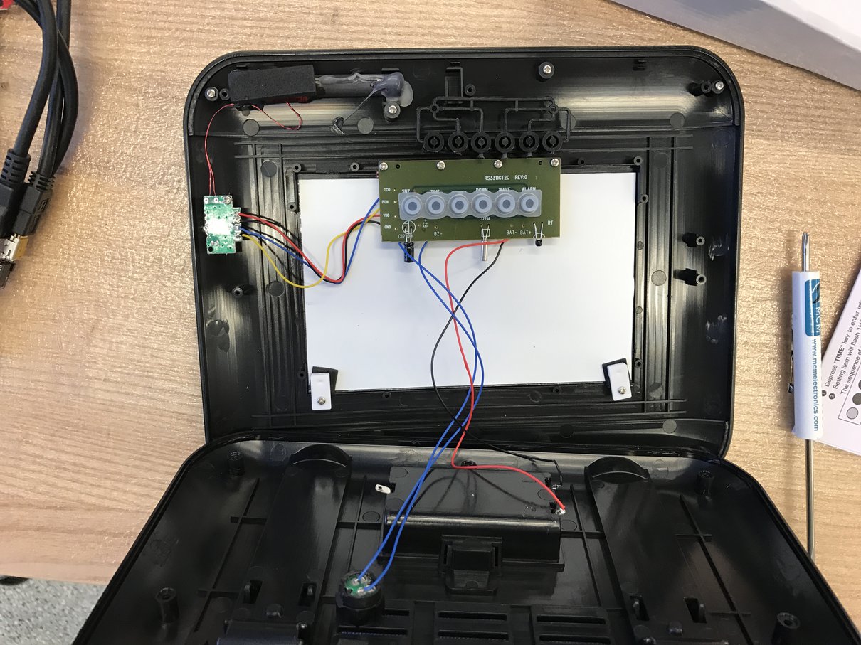
Here is the final assembled watch stand, snap-fit together:
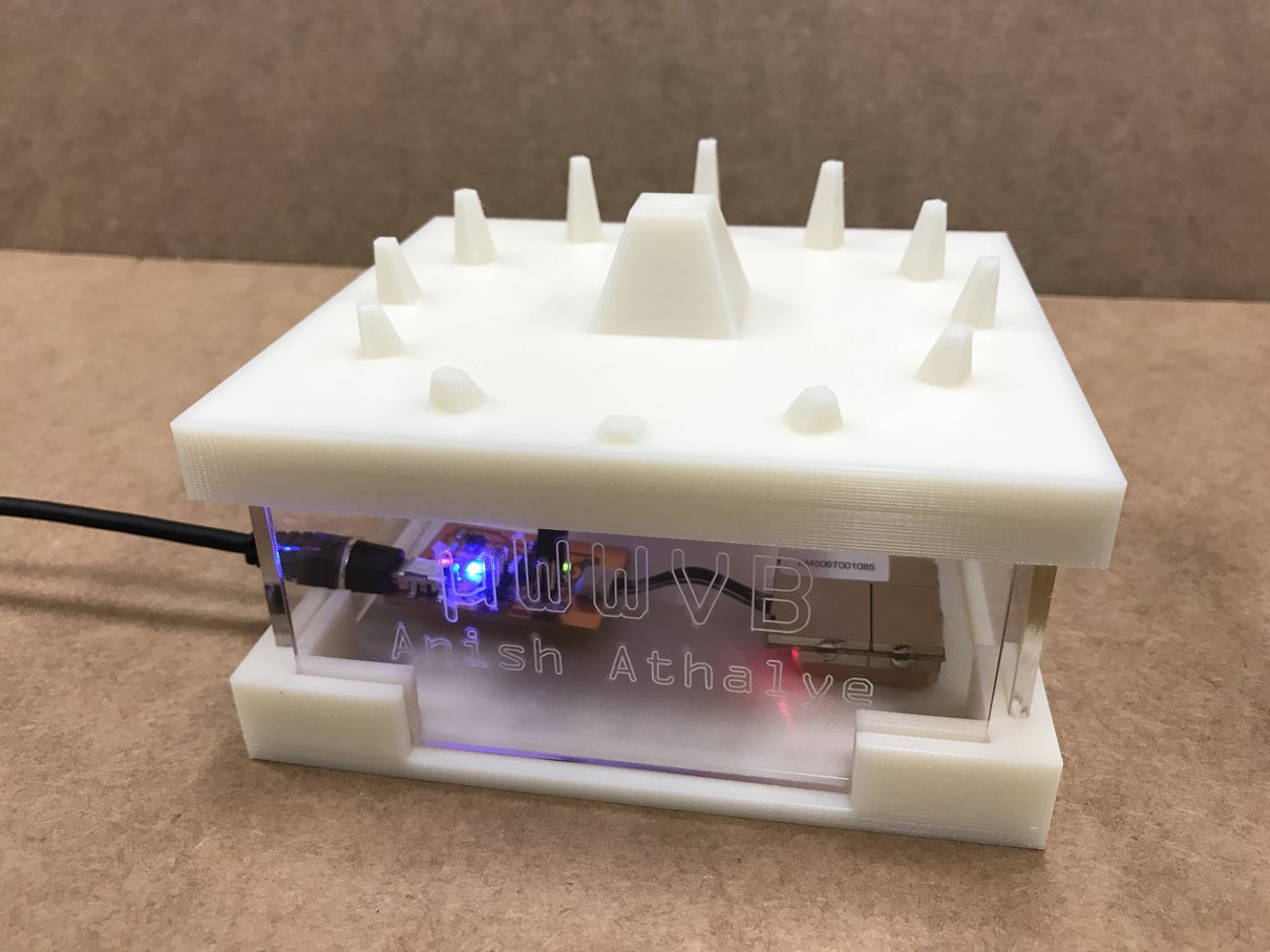
It works to automatically set my watch (which auto-receives every night)!