Week 11: Output Devices
23 Nov 2016 · 3 min readThis week’s assignment was to design and fabricate a microcontroller with an output device. This week, I decided to keep it simple and design a board with an RGB LED. I also included an FTDI port on the board so that I could later program the board to interface with a computer over USB.
Design
After designing a couple PCBs over the last couple weeks, I’ve gotten fairly comfortable using EAGLE. Here’s my schematic and board design:
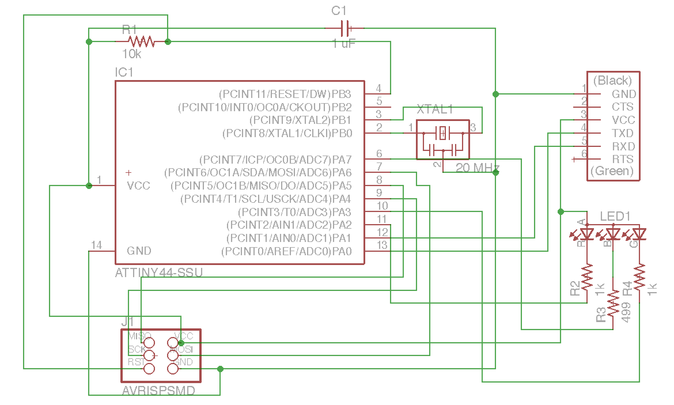
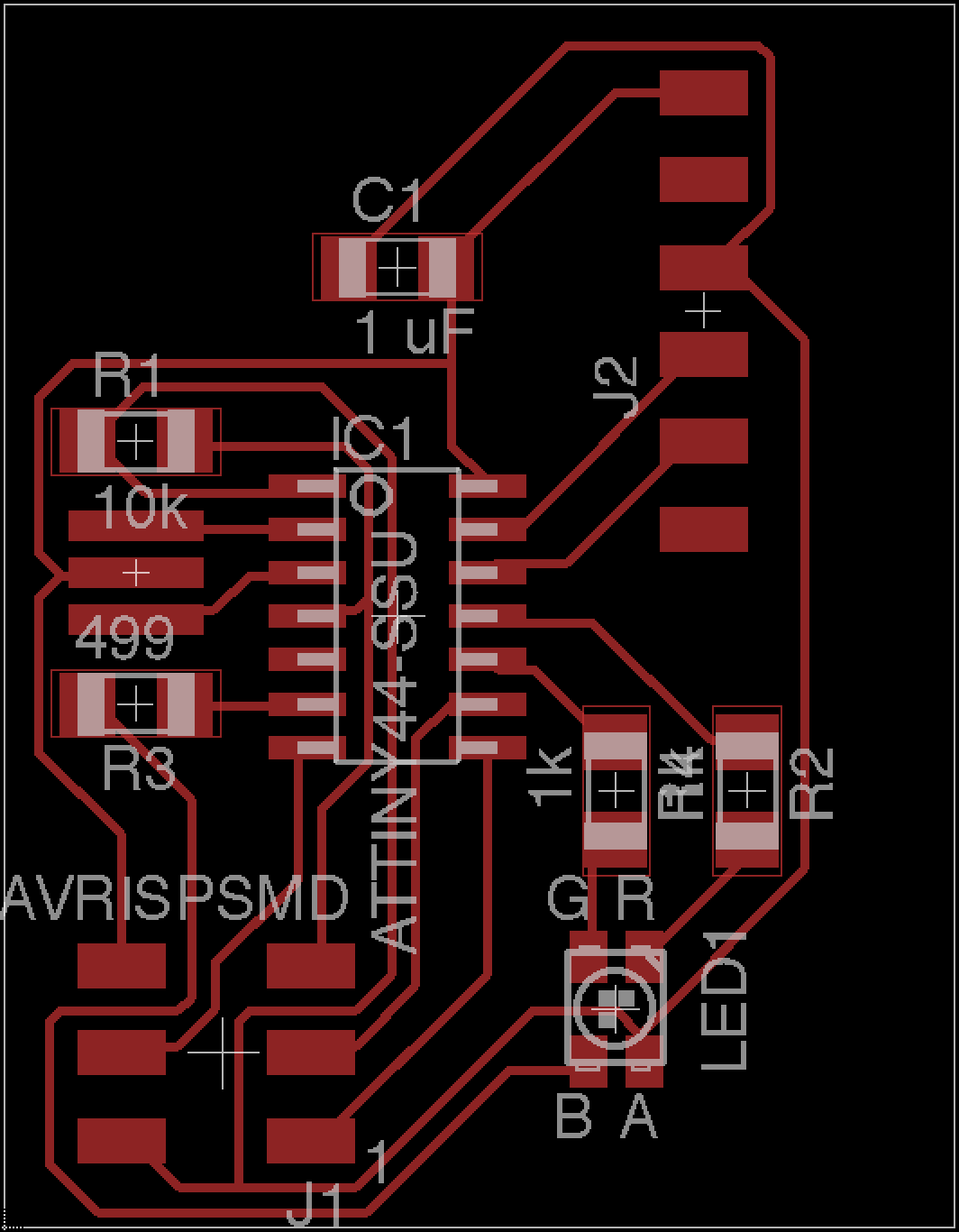
Production
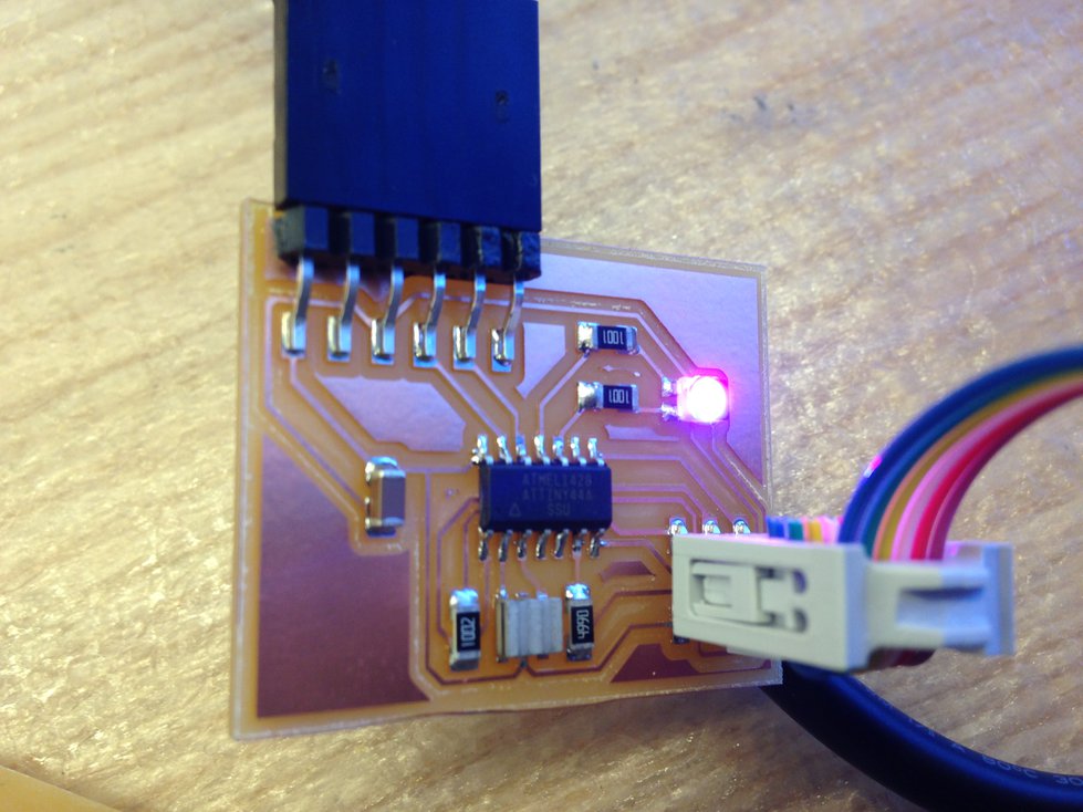
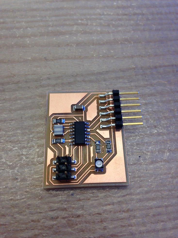
Following the same procedures as in previous weeks, I milled my board on the Roland SRM-20. This week, I decided to use solder paste when stuffing my board. The procedure was really simple — I carefully put solder paste on pads, placed components, and then I used a heat gun to solder everything. It took about ten minutes to complete the entire job. Here’s the end result:
Software
For now, I’m not using the FTDI port on the board. I wrote some software that cycles through colors on the RGB LED, going through red, green, blue, cyan, magenta, yellow, and white. In the future, I might experiment with using software PWM to get more colors.
Here’s the code I wrote:
// blinking LED
//
// set lfuse to 0x5E for 20 MHz xtal
//
// Anish Athalye

#define LEDPORT (PORTA)
#define LED_R (PA2)
#define LED_G (PA3)
#define LED_B (PA7)
#define SETB(byte, bit) (byte |= (1 << bit))
#define CLRB(byte, bit) (byte &= (~ (1 << bit)))
#define ASSIGNB(test, byte, bit) do { if (test) SETB(byte, bit); else CLRB(byte, bit); } while (0);

#include <avr/io.h>
#include <util/delay.h>

int main(void)
{
    // set clock divider to /1
    CLKPR = (1 << CLKPCE);
    CLKPR = (0 << CLKPS3) | (0 << CLKPS2) | (0 << CLKPS1) | (0 << CLKPS0);

    // set to output port
    DDRA |= (1 << LED_R | 1 << LED_G | 1 << LED_B);

    // cycle through colors
    while (1)
    {
        for (int red = 0; red <= 1; red++) {
            for (int green = 0; green <= 1; green++) {
                for (int blue = 0; blue <= 1; blue++) {
                    ASSIGNB(red, LEDPORT, LED_R);
                    ASSIGNB(green, LEDPORT, LED_G);
                    ASSIGNB(blue, LEDPORT, LED_B);
                    _delay_ms(1000); // wait for a second
                }
            }
        }
    }
}
Result
Here’s a picture taken while running the program: