Wow I'm starting to run out of introductory things to say. That slot for an intro paragraph at the top really likes to hog the spotlight. I guess now would be a good time to provide actual links, talking about my inspiration and whatnot. So I bought a large roll of LEDs as a freshman, as is customary. I was too hosed/lazy to actually paint my room, so in my head using LEDs would allow me to color my room without any actual effort. Then, in my freshman seminar, an EE friend of mine started bragging to me about his LED setup, and I learned about how the tin foil touch sensor for the first time. This site served as a pretty good starting point for me as a freshman, and I continued referring to it for this project.
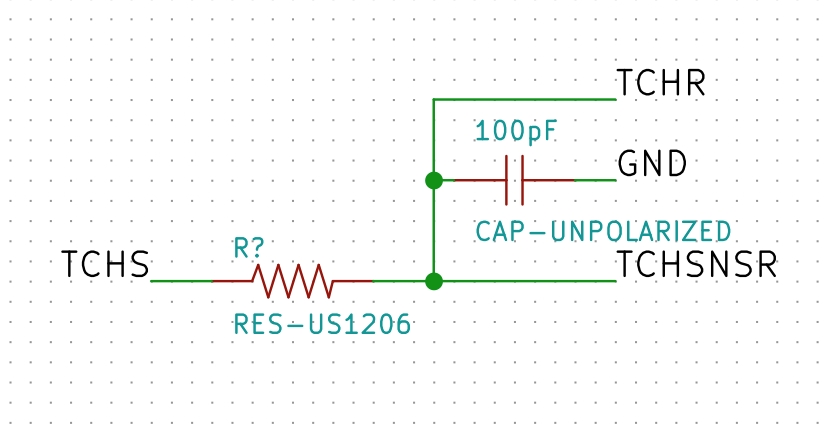
Touch sensor circuit in KiCad
When you touch the tin foil, your body becomes part of a capacitor. The capacitance increases as you get closer to the metal, and drops to nearly zero when you are far from in. By measuring the time it takes for a receiving pin to reach the same level as a sending pin, one could figure out how much capacitance the sensor is detecting. The key is a 1MΩ resistor, which multiplies any trace capacitance, allowing it to be more easily detected (I think). Luckily, I saw MΩ resistors were in the fab inventory, so my crazy plan could work after all!
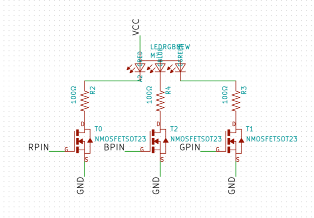
Thank god the fab inventory also had RGB LEDs
Also thankfully the fab inventory also stocked RGB LEDs! However, this design has a glaring flaw: It uses more pins than are free. The RGB mosfets take three pins, the touch sensor takes two pins, and the button (which is there in case the touch sensor doesn't work) takes one pin, and only four pins were free. My solution: Add switches that route pins PA5 and PA6 to either MOSI/MISO or I/O pins.
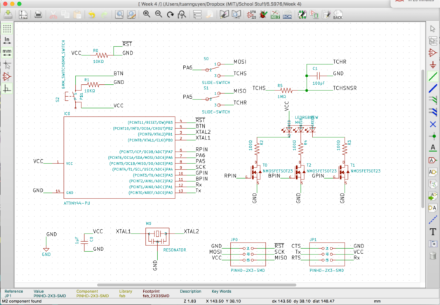
I'm just praying that the layout works at this point
Next was to actually design it in KiCad. I chose KiCad over Eagle because it had an improved UI and some handy features that are useful for designing tiny circuits like ours. For example, when laying out the footprints, it boxes each footprint, and doesn't allow traces to be within a certain distance of footprints it isn't directly supposed to connect to or other traces. And you can specify these parameters as "design rules", and then check later on whether you are following all of your design rules. Overall, the only real reasons I could see for using Eagle were 1) tradition and 2) learning it for career purposes.
I used the Getting to Blinky tutorials on Contextual Electronics to learn the design flow on KiCad, which was a godsend. At first I just tried to lay everything out separately, using labels to denote where wires should connect. I figured that when I put the groups together in the footprint editor, I could just add 0Ω resistors after the face as I saw fit. However, when I transferred from circuit diagram to footprint editor, I saw this:
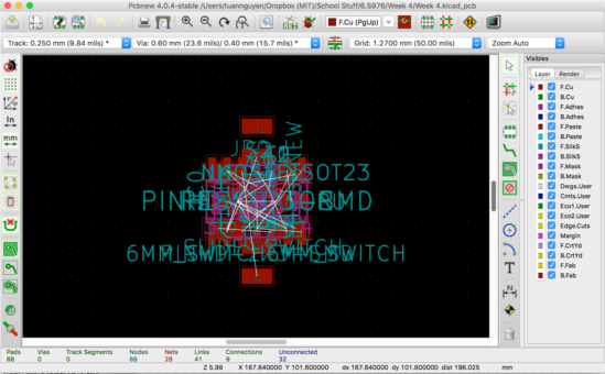
I really started hating KiCad at this point
I didn't realize at the time that I could have fixed it by right clicking and picking some options (not sure why those options aren't default grumble grumble). Instead, I thought the solution was to explicitly connect the circuit together, which gave me a chance to actually plan the circuit out and see where 0Ω resistors were needed to jump a wire here and there.
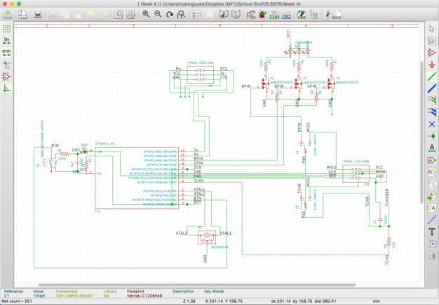
Adding explicit connections between everything
It was at this point that I realized two things: First was that the schematic for the ATtiny44 was not topologically equivalent to the actual chip!!! I'm not sure who made this design choice, but it actively made it harder for me to design the circuit with the footprints in mind. Last was that in the footprint editor, designing it ahead of time in the schematic is better than adding 0Ω resistors later because it shows you where you need to make connections. This makes organizing the board and seeing alternate paths for placing the traces easier!
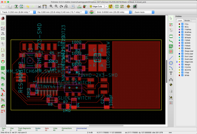
Finally fiddling with the footprints
When I transferred the schematic to the footprint editor this time, I saw the same garbage. It was at this point where I learned you could spread them out by right clicking some things (which was good because I did not want to move each individual piece separately :c ). I would actively switch between schematic and footprint editor, expecially when I saw connections in the schematic that didn't translate to what I wanted in the footprint editor. I'd make the change in the schematic, then redo the transfer process so that it would automatically change pin positions or add new components. It was therapeutic to see the white lines showing what components needed to be connected disappear as I added the traces.
The universe hates me
When it came time to actually mill the traces, I had noticed from fab mods that a lot of the traces were too close together. It was at this point that I noticed the design rules were all in millimeters instead of inches... CHECK YOUR DESIGN RULES KIDDOS!!! I tried to solve this by changing the mill diameter, but then it resulted in the above monstrosity. I fixed this by actually moving the traces on my design further away and by decreasing the width of the mill in mods, but it would have just been less of a pain if I had noticed earlier the units of the design rules.
Resister leads are so functional
When I finally milled out a successful board, disaster struck! probably because the tracks were smaller, when soldering one of the switches on, the traces attached to it ripped off. I tried super-gluing the tracks back on, but I ended up supergluing the switch and making it unusable. And then the traces & switch completely detached :c To fix the problem, I used solder to hold the tracks back in place and I replaced missing track with part of a resistor lead, also superglued to the board. From there I soldered a new switch and everything worked out fine!
Here is the png file of the traces and here is png file of the outline