My first idea for a final project was the ferret puzzle feeder. However, I started disliking how oddly specific it was, and tried toying around with more artistic/robotic-y ideas.
Quick sketches of final project ideas
I started coming up with new ideas during the input devices lecture. The first new idea I came up with was a large, prototype nanobot-like thing. I wanted each robot to sue a step response sensor and a six-axis accelerometer in order to know its orientation with respect to each other robot. I also wanted to have them be able to move relative to each other, but I had no idea how to accomplish that. Ultimately, I decided against this idea as my final project because without the moving capabilities, this idea would be too similar to another student's final project idea.
The other idea I came up with in class was something dealing with reading a point in 3D space using three step response sensors. Then, it would take this point and translate it into motion for a robot arm or for a videogame type-thing. I was going to make this my final project (and even designed a circuit for the pen), but the "sensing a point in 3D" was quite a difficult problem. I ended up being very behind in class as well due to taking on too many responsibilities in theatre, so I decided against trying to make this my final project.
Other ideas that I gave thought to include a pen equipped with a six-axis accelerometer and a step response sensor between the tip and a metal plate underneath a piece of paper. Then, reading strokes using the two sensors, I'd feed the data into a machine learning algorithm in order to turn the pen's movements into characters on a word document, so you could take notes in class and have an electronic word document of your notes.
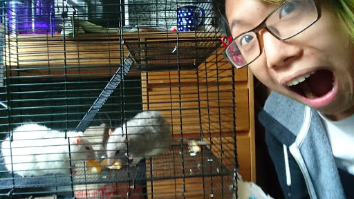
I am the rat king
As a result of me being amazingly behind, I started to brainstorm ideas that were simpler. Going back to the my original concept of pet-related proejcts, I then had the idea of making cat guard for my door. I enjoy having my door open 24/7, but I also need to prevent the cats on my hall from getting close to my beautiful pet rats. So, an interesting final project would be a cat guard that stays low enough for a human to step over until it detects a cat within range. Then the door would rise, so that a cat could no longer jump over it. In terms of input devices, it would mainly be a camera that looks for some mass that stands out from the background, and sees if it is small enough to be a cat.
Finally, after a fun night on hall the day after Thanksgiving, I settled on a definitive final project that is fun, simple, and possibly artsy(?) I was inspired by Calvin Zhong (one of the architecture TAs that lives on my hall), where he started making a strange and annoying sound. This prompted another hall member to say "they wished that they had a Staples 'that was easy' button, but instead with that sound". And thus was the birth of the Blank Button! It is a button styled after the Staples "that was easy button", but records a sound when you first hold down the button and plays it back on every subsequent button press (and you can't change the sound you originally recorded onto it unless you reprogram it or something). To this end, I'm making my input/output device projects simply be the recording and playback circuit.
My game plan was to make all of my EE-heavy projects build towards my final project. Starting from Week 8's project, I started trying to see if the data from the microphone could be played back by my laptop. I only had to modify rx.py so that it also packed a file sound_float.txt with the 32-bit float representations of the data, since Audacity can import RAW audio files (which include literal float values). It's important to make sure the values are between -1 and +1, otherwise it gets clipped. To pack the data I used the python struct module.
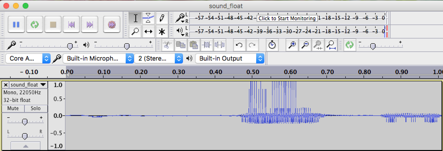
MP3 here (trust me there's a link there)
Setting the ADC division factor to 16 and changing the baud rate to 921600 b/s allowed me to record data to my computer with a sampling rate of ~22kHz. The goal is to eventually have a sampling rate of 44kHz, which is the minimum sampling rate for recording human-audible sounds. This should be pretty easy once I'm not worrying about serial baud rates. I noticed some clipping, so I muffled the microphone with layers of cloth. And it comes out pretty clear! I think that in the next board, I will lower the gain by adding a resistor and using a buffer + voltage divider to fix the bias issue (notice how only the bottom is clipped).
From here, I am going to make my next prototype board, which will also be my Week 12 project!
Now to CAD the actual body itself. I used this instructable to see how the original button design worked. Specifically, I wanted to see how the large button fits into the frame, because I had a hard time imagining how that would work. Ultimately I came up with the following design:
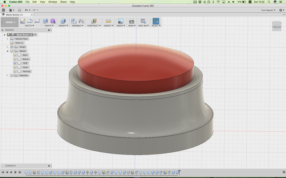
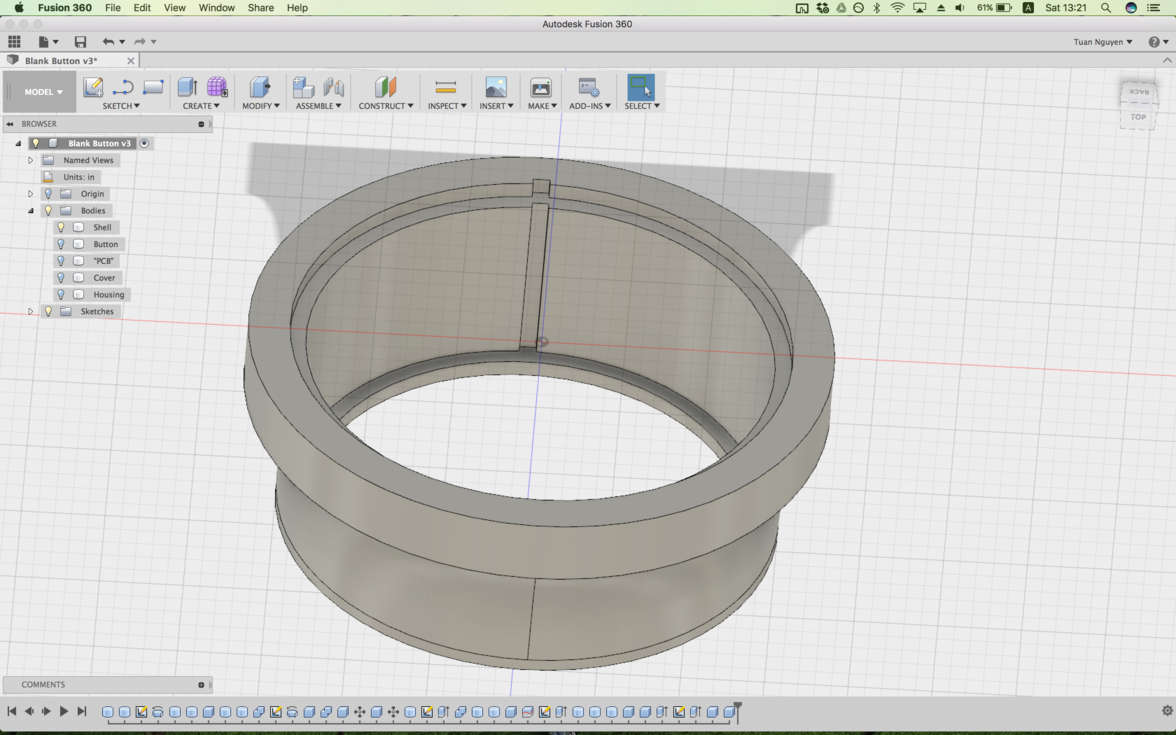
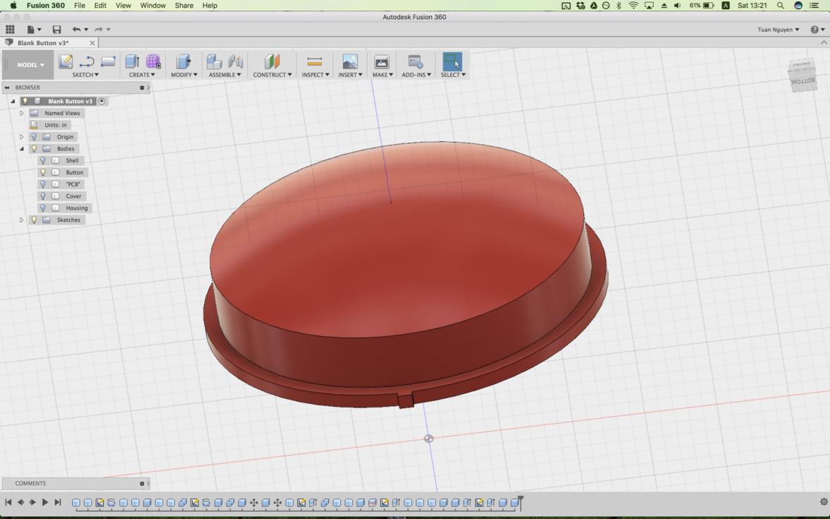
My counterfeit Staples Button
It consists of an outer shell, where the inner components are stacked on top of each other in a cylindrical fashion. The giant red button is pushed to the top by the components below it, but is kept from escaping by a clever bevel in the shell. Then, I made a crude model of PCB. As discussed in Week 12, I used Eagle to design my ultimate prototype board because I wanted to use its purported Eagle -> Fusion360 functionality to see how it'd fit in my button, but it ended up 1) being in a very developmental stage 2) requiring a subscription/30 day free trial and 3) the software was quite confusing, and the library of 3D models wasn't even very extensive at all. My crude model of the electronics was just a thin sheet of FR1-thickness with a rectangle the height of the physical SMD button.
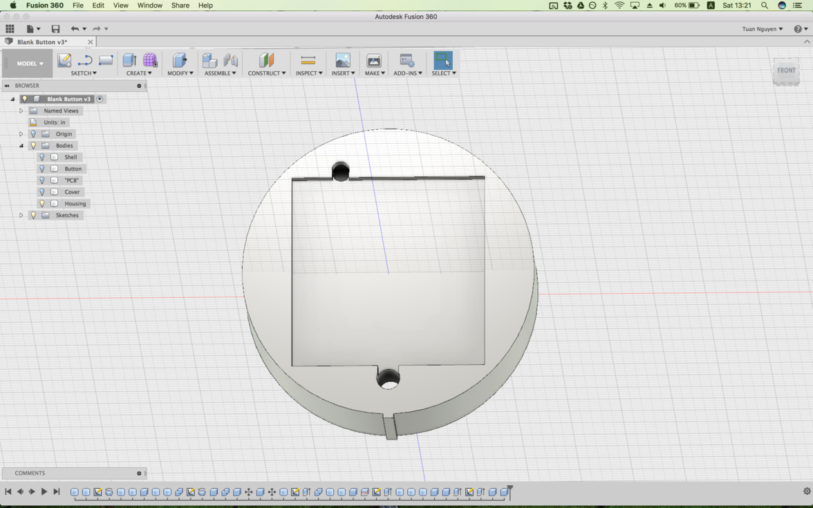
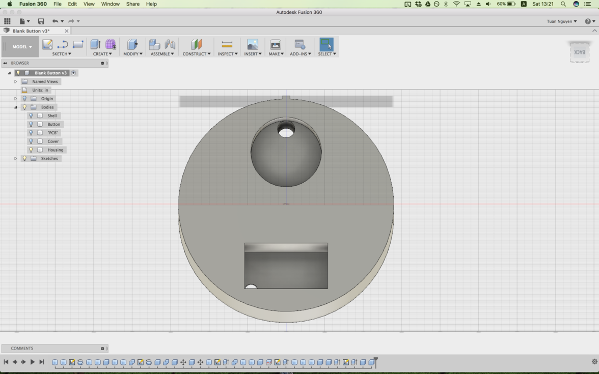

My counterfeit Staples Button
With the rest of the space not taken up by the button, I put a housing for the circuit, battery, and speakers. At the very bottom is a cover that should fit snugly into the bottom of the shell. The key idea is that the circuit should sit flat against the large red button, with the SMD button being the component that sticks up the highest so it contacts the physical button. As such, I decided to add a hole for the 220μF capacitor to hide in. This also means that the speakers and battery won't be connected via pins, but by having the wires be soldered straight to the circuit.
My original intent was to mold and cast every single piece (there being 4 pieces, 2 simple ones and 2 complex ones). However, due to lack of time and patience, I am only going to mold and cast the three exterior-most components, and 3D printing the complicated electronics housing component (which would require a very omplex mold anyway).
Not even close
The nice thing about 3D printing this component now is that I get to see if there's an error in my sizing. Like above.... Thankfully everything else, from the compartment for the board to the speaker, fit perfectly! It was just that I got the size of the battery wrong by an order of magnitude.
Electronics Housing Redesign
I redesigned it with actual measurements, and the result was just astonishing. The housing worked just as I had hoped it would! Next I focussed my efforts on molding and casting the body. This took a very long time because each rough cut took 3-4 hours plus an additional 2-3 hours for the finishing cut. With two simple shapes and one complex one, I had to mill out four molds, which ended up taking me the entirety of the weekend right up until late Monday night/early Tuesday morning, which I did not anticipate when I first thought about the design. However, the alternative was to 3D print everything, which would have been annoying since other people desperately needed to 3D print for their projects.
Post-processing
With my model I didn't actually add any spacing between the piece. I tried fitting some of my pieces together, and saw immediately that it was more of an issue than I had originally thought :/ The solution was simple: post-processing! I took several files and sand paper and shaved off the inner mold for the shell so that the final product would be wider and more easily fit the components.
One of these things is not like the other
With way too many days of work, the molding and casting was done. Timing was tricky, because in order to maximize efficiency I needed to be in lab 24/7. Also, in the stress of trying to finish in time, I got sloppy with the measuring of the OOMOO parts, eyeballing volume instead of using weight. As a result, my last mold took 8 hours to set enough for me to handle it! Also, in the heat of battle I accidentally grabbed a box of Sorta-Clear instead of OOMOO, as you can see in one of the molds below.
The face of evil
My original intent was to use the Smooth-Cast 326 as my casting material, because I wanted to replicate the plastic-ness of my inspiration. However, upon reading the material safety datasheet, it became clear to me just how dangerous the material was. My personal favorite line was "fatal if ... in contact with skin". sad face. Anyway, if I wanted to use it in the EECS section, Gavin told me everyone in the lab would have to wear a respirator, so I opted not to do that for everyone else's sake. I then emailed some staff-members of the Architecture section if I could use their fume hood. They agreed, but my poorly-ratioed OOMOO did not cure in time for them to help me use the fume hood, so I defaulted to good ol' hydrostone. I had a bad experience with this material for my Week 7 molding and casting project, but this time went very smooth!
Casting with Hydrostone
Now, onto the EE side of things. This was my first time working with an ATxmega, so I read the C code w/ xmega intro document. Overall, I'm very impressed! Writing code using bitmasks and bitgroups isn't that much more different than writing directly to registers (trust me, you still need to pour through all the datasheets and junk) but is much easier to read what you did. Plus, with more keywords I can more easily search the datasheets with ctrl-f.
Sadder than the titanic
And then tragedy broke out! A whole host of unfortunate (or fortunate?) things happened with my board. First, the 2x3 ISP header pins got yanked off by accident, almost to the point of being irreparable, so I snapped off that part for good. It let me see if my board would fit well into my enclosure, which it absolutely did! This was at a point when I was having trouble programming the board. What I did not know at the time was that the ATxmegas can't be programmed via ISP, and instead use a new 2-pin system called PDI. So snapping off the ISP pins was useful anyway since I had to solder some wires directly to some pins on the ATxmega.
However, I continued running into problems. Next up was the fact that the version of AVRdude on CrossPack didn't have compatibility with the Atmel-ICE, which was also the only board that could program the xmega. Doing a brew install fixed that, but it did not make my board programmable. Apparently Mac's have a problem with the Atmel-ICE's, trying to see them as USB devices rather than programmers. It took me literal hours to find a fix, which involves a kernel hack of some sort where it forces your computer to see it as a programmer. Then and only then was I able to program the board.
Final Button Cast
And now we're here. That was 6am Tuesday 12-20, and I had run out of time. I did put my bad 3D printed electronics housing in with the cast parts to see how they'd fit. And fit they did!