Final Project
Alternate World Chess Set!
Main Page
Back Story & Founding Ideals
From Wk0 page to now I've shuffled a bit in my mind what sort of project I want to end with in this course. From the illustrious Ego Pod to my Bilingual Word clock, I am going to focus on something currently tangibly more at hand and relevant to me.
Tiny Backstory: I love chess. I used to play as a child all of the time, and had this beautiful glass chess set that each weekend I would play with my father. Until one day, my cousins who were visiting shattered most of them as they were running around the living room. All that to say, I was devastated and never played chess again.
Although I would love to create a glass chess set, that's unfortunately not in the scope of this project. Instead, the storyline behind this project focuses on flipping the narrative and social hierarchies that exist within the game of chess.
Patriarchy -- The king being the most important piece. The entire game revolves around capturing the opponents king, an adequate reflection of our present world. Men remain very much in positions of power, regardless of how much 'equality' you might choose to see. Our system is a patriarchy and embedded very finely with this is what I shall denote --sexism-- or perhaps more palatable, "sexist tendencies".
Classism -- The role of the pawn in chess is very much one easily dispensable. The 99% if you will. Of course, they are necessary, because without them you wouldn't have the labor force, the intermediary between the imminent threat, but when you lose one piece, it's okay, because at least you still have your other pieces of royalty.
Alternate World Chess Set
In this Alternate World Chess Set, I want to highlight the power of the pawn. If you're familiar, what happens when your pawn makes its way successfully to the other side of the board. You get to trade it in for a piece of royalty, the most powerful being the Queen. To be honest, this is my trademark strategy, because who sees that coming. The pawn is often seen as a piece of disregard. So what happens when you begin to realize the power that exist within this seemingly dispensable piece.
Using Step Response for Input Device week, I will be able to track the position of each pawn as it moves across the board. This input will be connected with a series of RGB LED's which, as the pawn moves throughout the board, a reflection of this positionality will be demonstrated through colors. In some ways, playing this game will unveil a dance of the movement as the pawns lives (voices) are amplified as pieces of importance.
Yes, the rules remain the same. To trap your opponents king, but in this process, realizing the power of the pawn and upholding the power of the Queen, the only perceived feminine (and might I add badass of the board) on this board.
2D Modelling
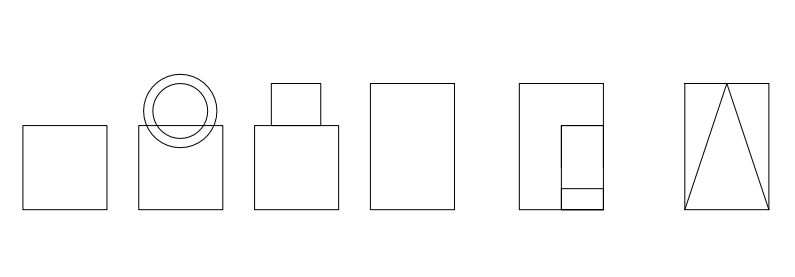
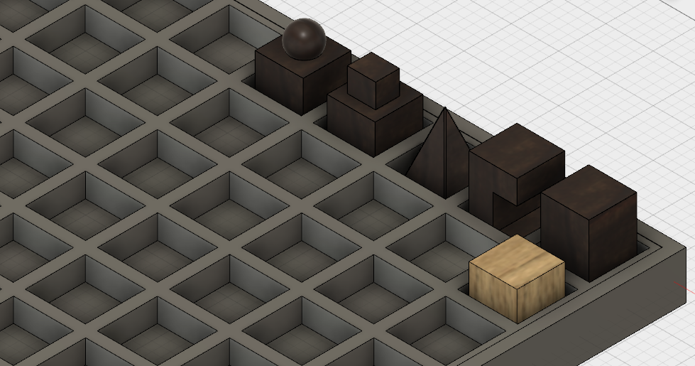
Inspired by the Bauhaus collection at the Harvard Art Museum, which connects both movement and form of each piece, I felt this idea was well suited. As an overall commentary on the way society has remained structured, and in some ways how our appearance dictate heavily the ways in which we can navigate our worlds, shaping my chess pieces in this way--almost perfection, wouldn't you say?
3D Modelling


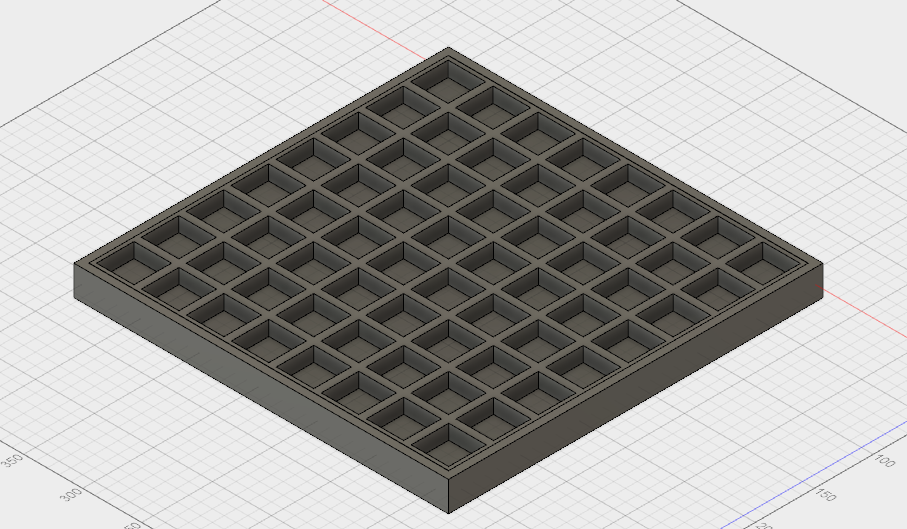
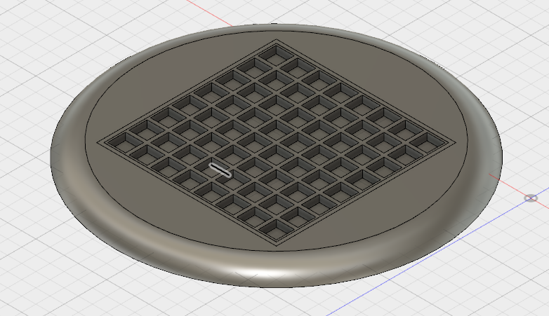
I worked within Fusion360 on a number of canvases to create my chess pieces and the board, extrusions and all. In the line of spiral development, I'm hoping to later down the line create a sort of table--clear acrylic would be best-- that holds this set as an inlay.
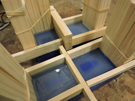
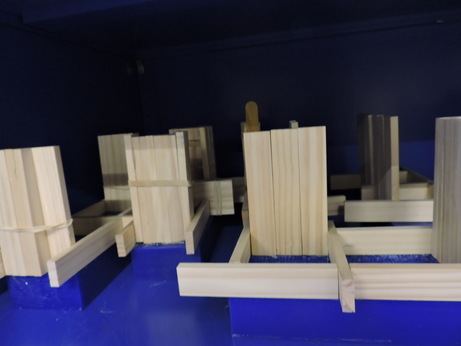
Molding & Casting
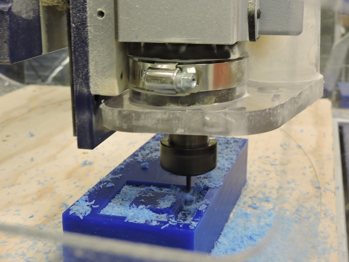
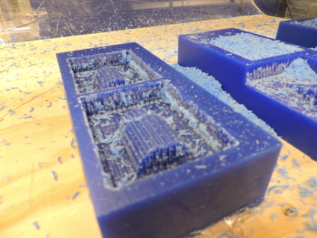
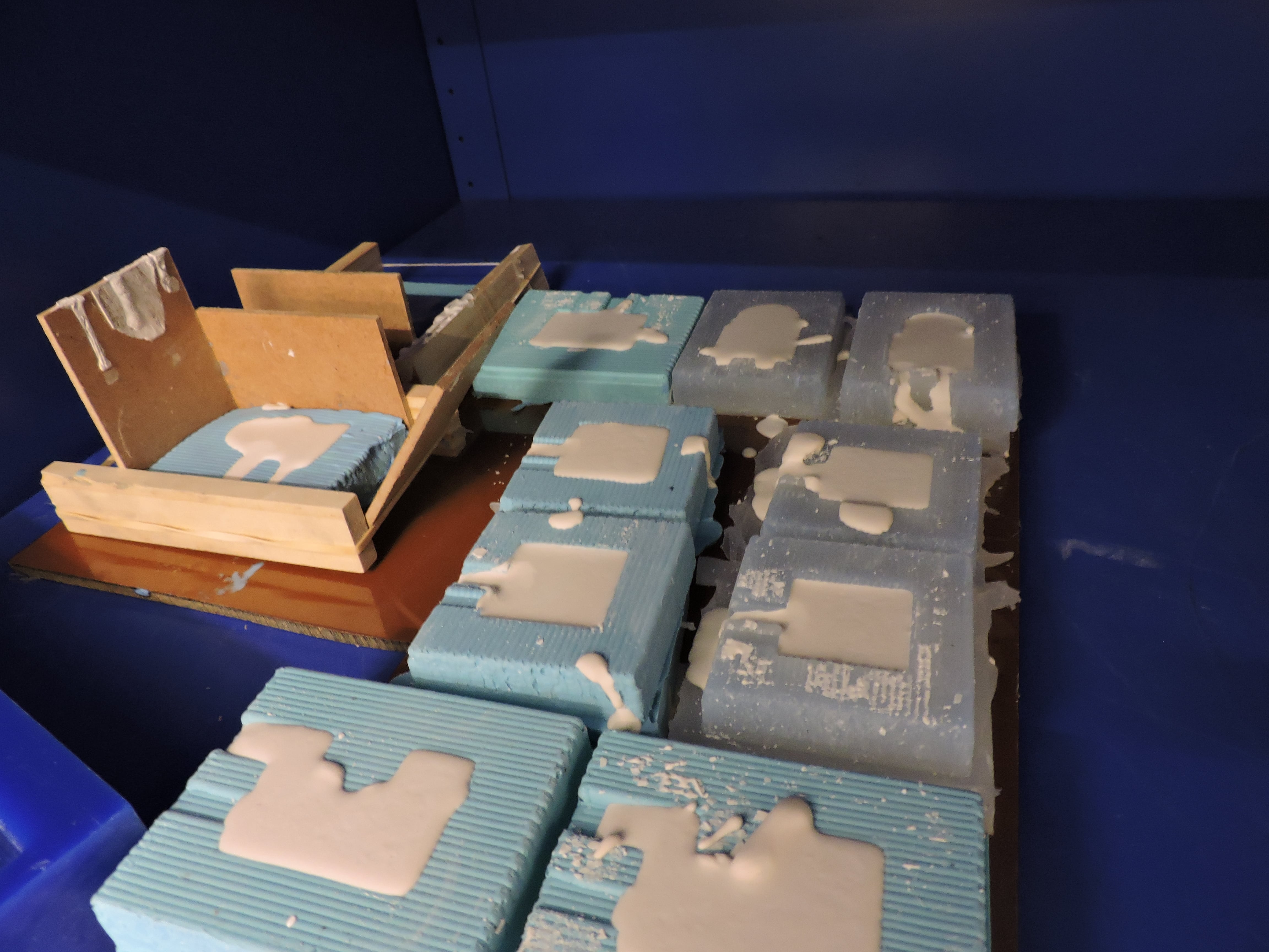
Because this entire project centers the Pawn, in a way that is not natural to this game (read: in this world), I wanted to represent that in some way. The purpose of this piece, in terms of function, as you will read later is to conduct electricity across copper plating and activate a light. So, it's technically what is hidden, what's in the underlay of the pawn that matters here. Regardless, I milled a block of wax for this to ultimately mold and cast in either Hydrostone or Liquid Plastic (I haven't decided). This process will be particularly useful since, I have a total of 16 pieces to cast.
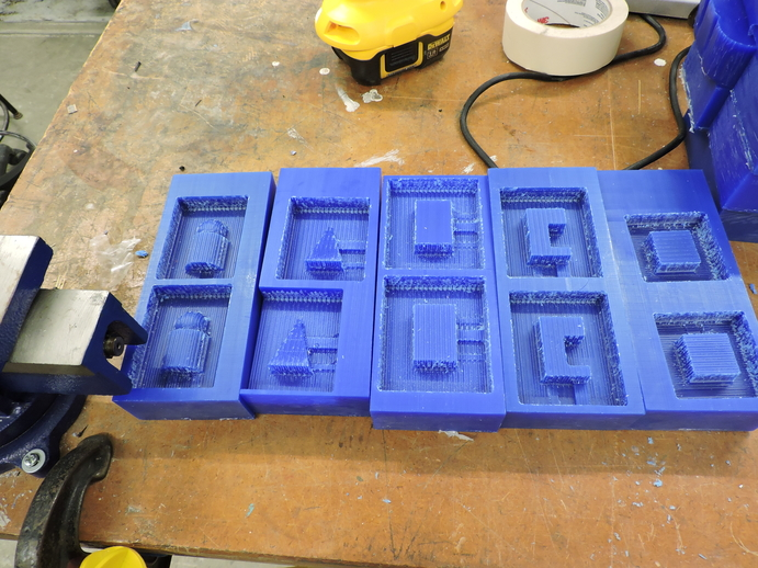
Similarly, I decided to mold and cast for the Queen, Rook, Knight, & Bishop. In terms of material, they will be made of Hydrostone or drystone. Maybe one side of one, the other of the other.
I imported the stl files into 3D Maker software and one half at a time (you have to create two halves of the mold for the whole piece), and milled the wax with a 1/8" bit. This was pretty straight forward, and realized well after this completion that my speeds were relatively lower than they should have been. Regardless, there were no issues with this process.
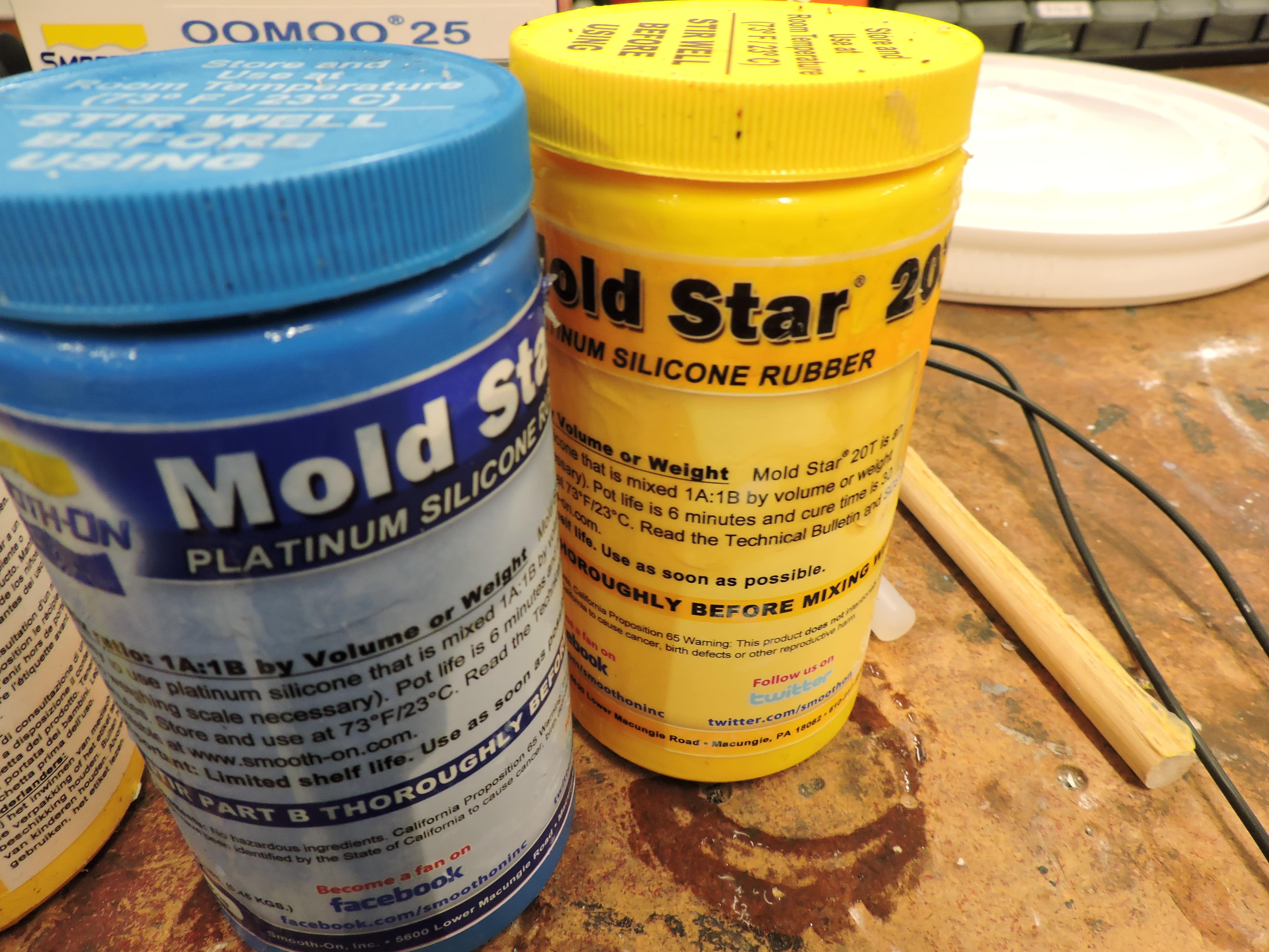
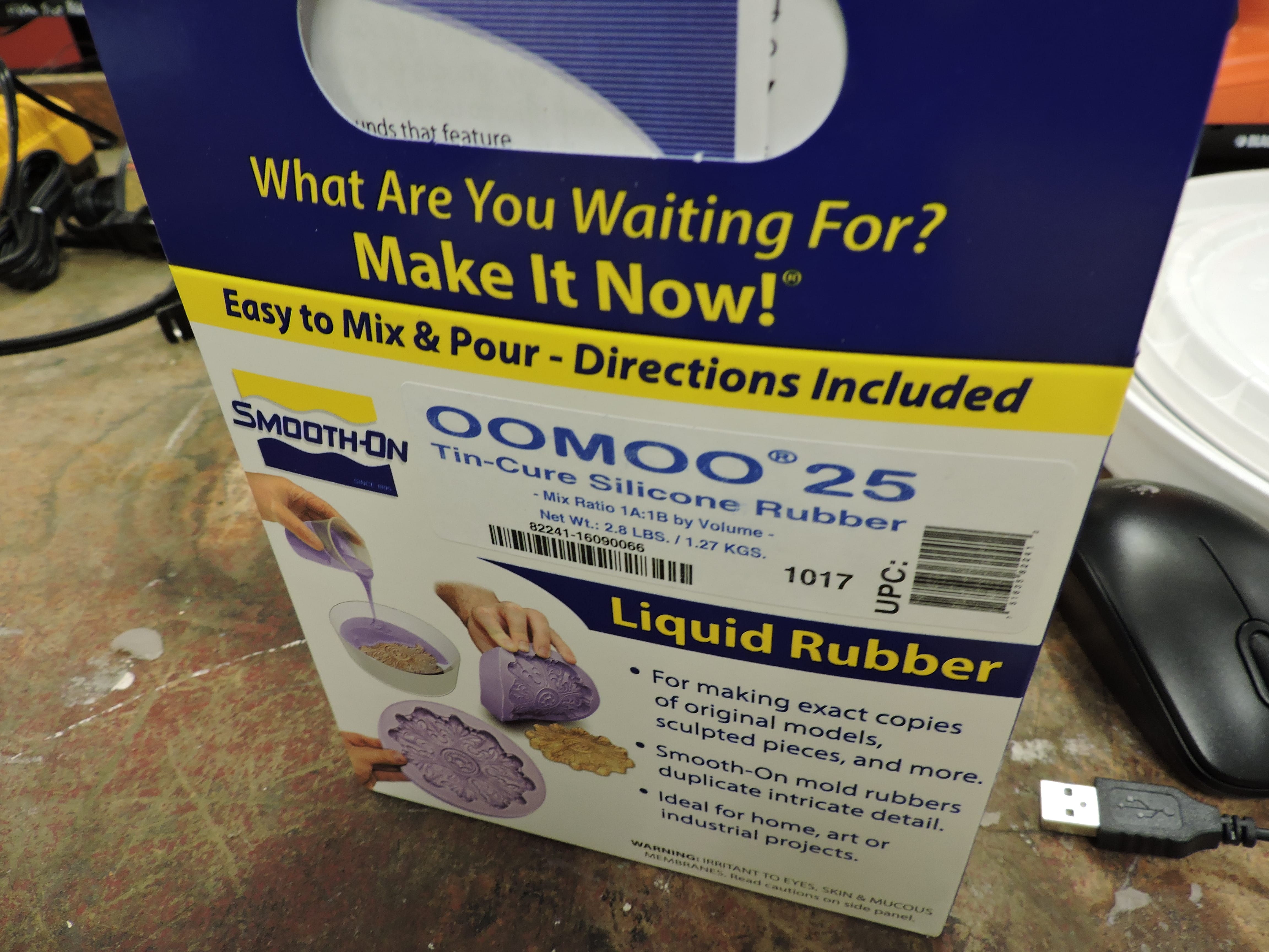
Currently waiting on more Oomoo to make my molds.
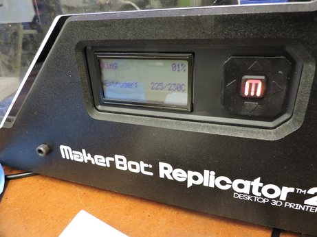
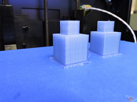
3D Printing
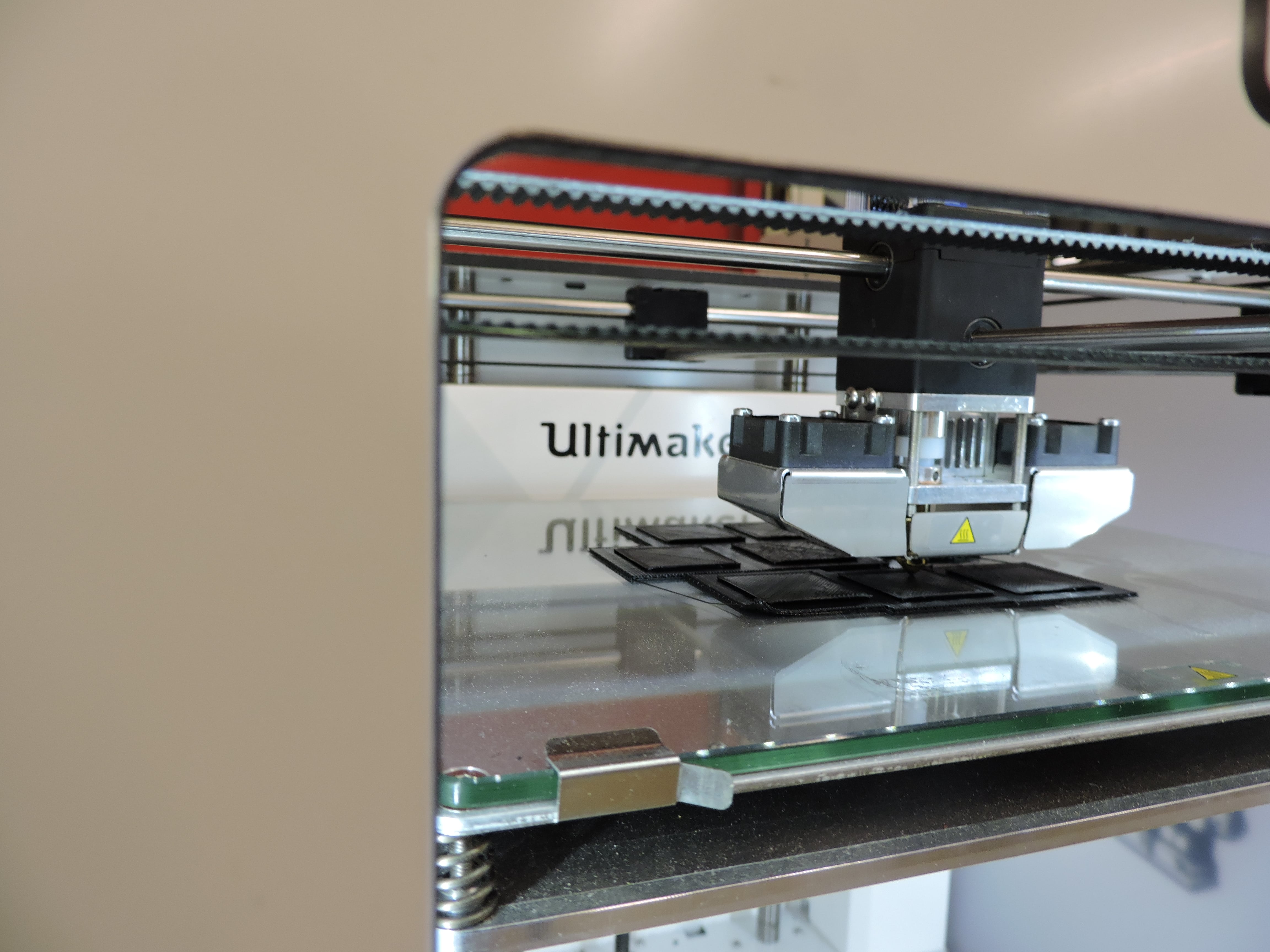
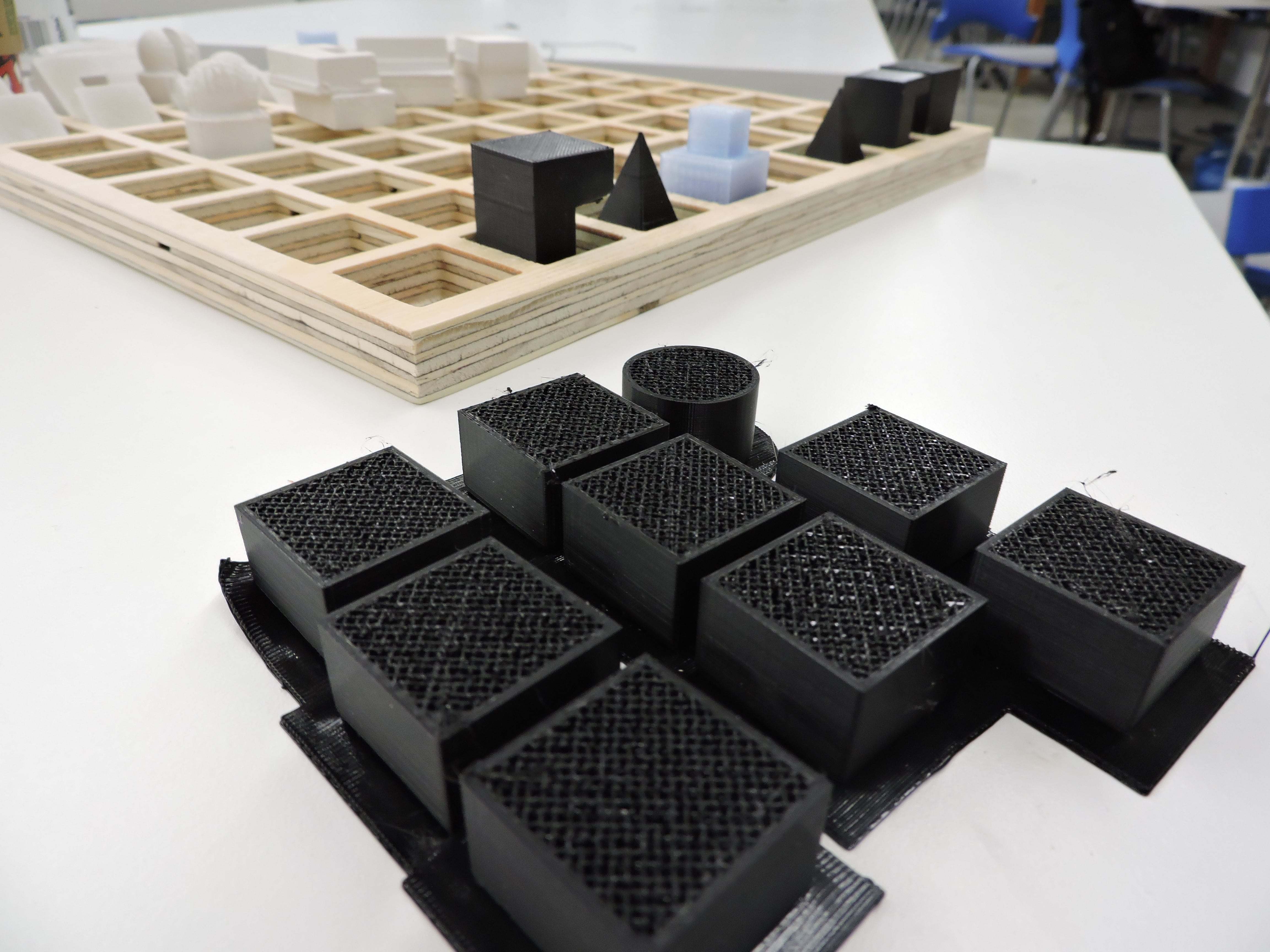
I decided to use the Makerbot to 3D print the King--using clear filament. This was very purposeful--primarily because I wanted to distinguish that this alternative world chess set was denoting the functions of power that lay within each piece, whether justly or unjustly so. Nevertheless, the clarity was to represent the illusion in notions of power and hierarchy. And yet, this print is rather structurally in tact, physically stable and altogether artificially created. Nonetheless, there is no denying the role of this piece, and position it holds.
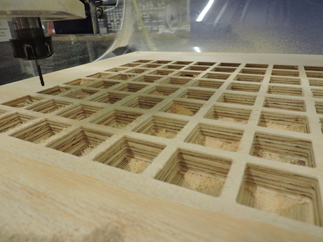
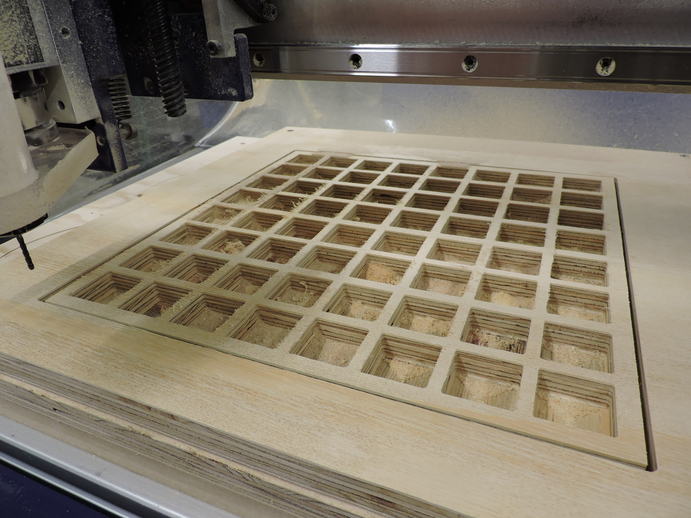
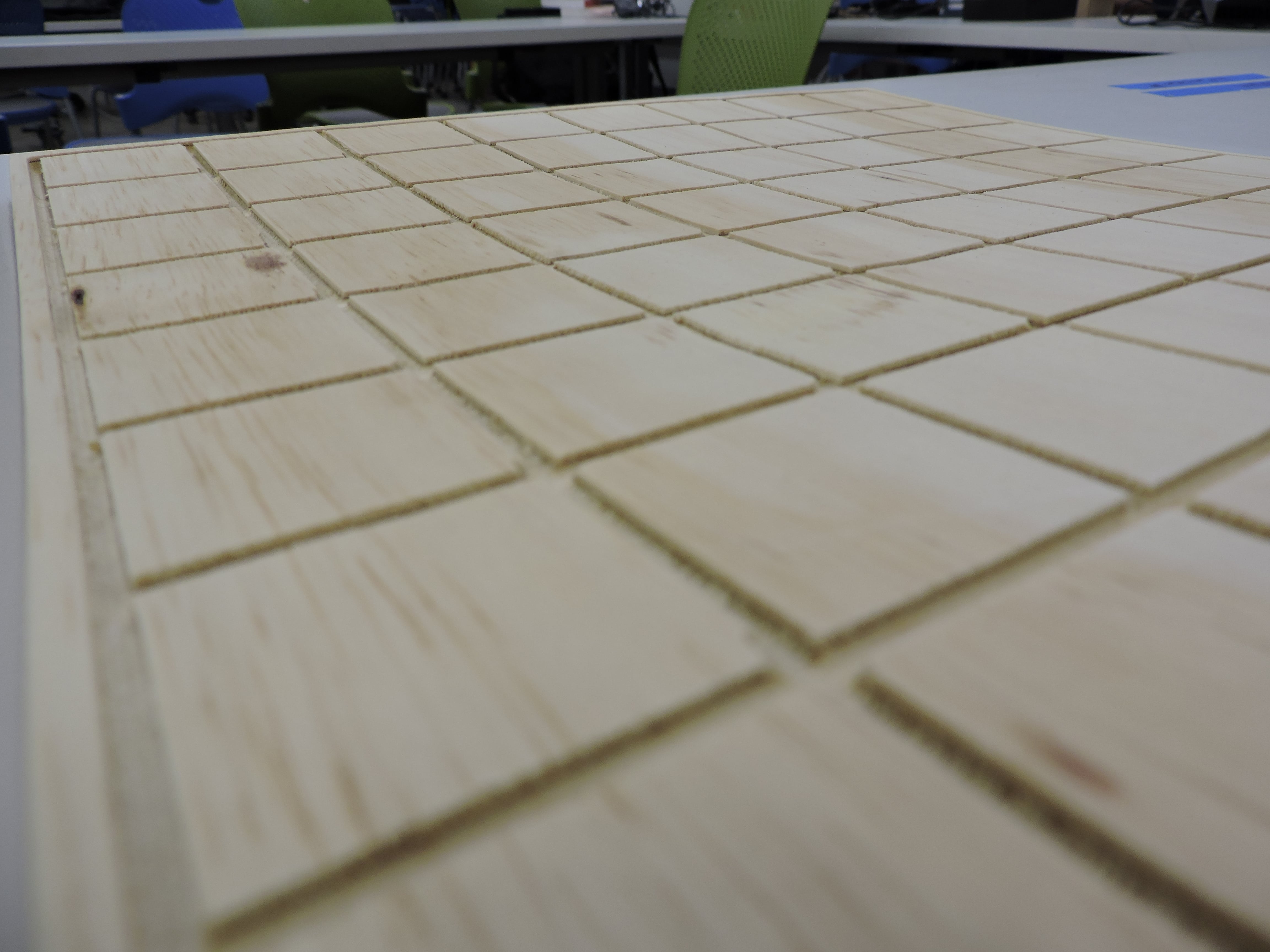
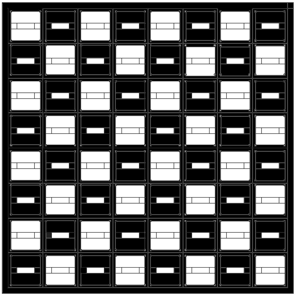
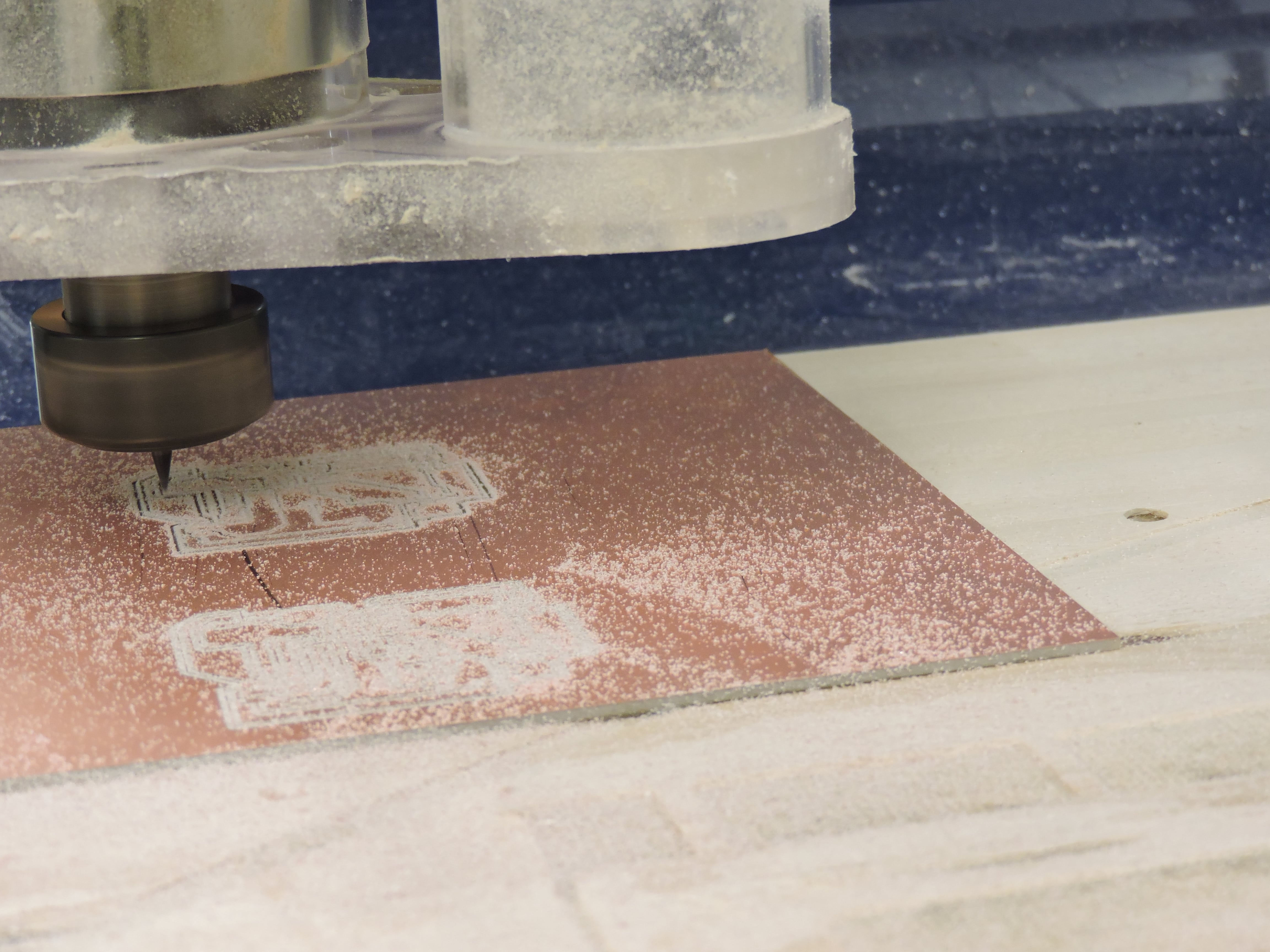
Computer Controlled Machining
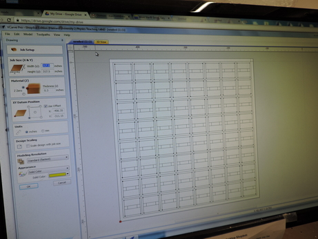
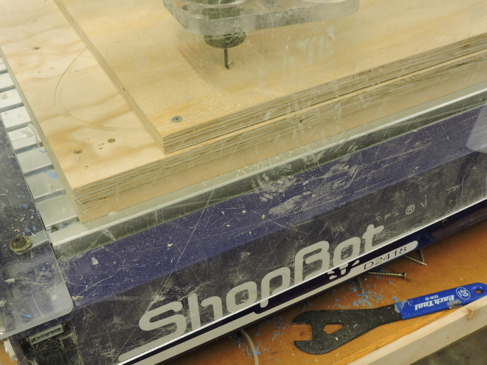
The chess board is physically composed of two main pieces. The top section, which connects directly with the chess pieces. Made of 17.37mm thick plywood purchased from Home Depot (sadly, I saw some quality issues after the buy), I used Vcarve to create toolpaths for my board--each piece will have a place holder that goes about 16.37mm (a little less than half an inch) deep--and the Desktop Shopbot to mill it out.
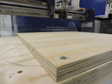
If you remember Week 9: Composites, where I milled a piece of styrofoam in the exact same form as this. That job was excruciatingly short, and for some reason didn't put two and two together to realize that this being wood, that would not be the case. 4+hours later...
Electronics
My final project requires the following components:
Step Response (Input): This will function as a distance sensor to determine location of the pawn on the board.
RGB LED (Output): This will function as the response to the pawn's location on the chess board. Dependent upon where the pawn is, the LED will shine a different color, along a gradient from blue to red.
Serial Communication: This will function as a means to connect all circuit boards of the chess board, and to in a future iteration read the data import from the step response and communicate to a computer through bluetooth.
Bluetooth: This will take place in a future iteration, functioning as a means to simulate the movement and dance of the pawn pieces on the board, in a variety of ways externally, other than light.
So, this week, I focused on integrating the first three components, in design and in code, and when time allowed (which it didn't really), considering possibilities for the bluetooth.
Messing with Code
Overall, I'm going to be using the ATTiny 44, which means regardless of what I do and how I'm using Neil's example as a starting point, which use the ATTiny45, I will be making some changes.
Step Response
As I stated earlier, I worked with Joe Negri to unpack exactly what was going on in the Neil's hello.txrx.45.c board and then Rob Hart to begin thinking how I could manipulate what was happening within this code to what I wanted for my project. Through these conversations, I was able to learn much more about the relationship between microcontrollers and how they denote, enable and disable Analog Digital Convertors. Not only was this helpful in beginning to unpack notions of time and loops within these programs, but understanding more intimately why and what needed to be changed in my using the ATTiny44.
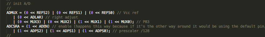
TxRx.45
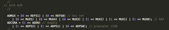
TxRx.44
Through this process, I also rid of the serial port section, as this code sends the data being imported to a program in python. That is clearly not something that I need for my progam. Additionally, I got rid of the for loop which adds cumulatively to the values of up and down. This will help in manipulating what I need from the variable I have introduced diff = up - down.
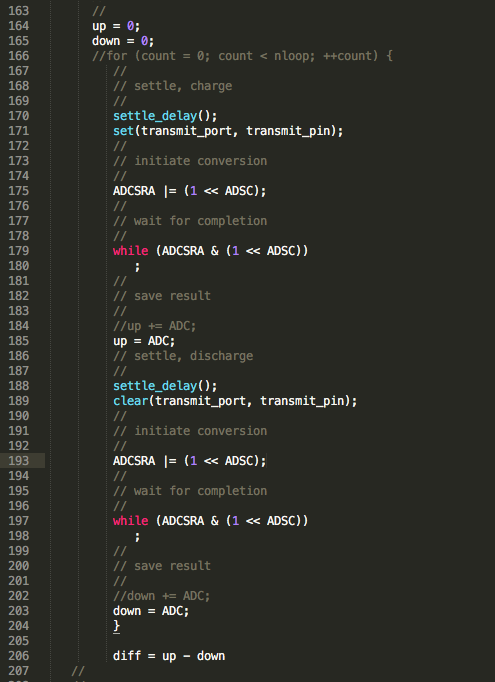
Some notes to keep in mind regarding code that will be useful for me down the line:
setthedelay() : time given to charge the capacitor
ADMUX : tells you which setting to use for the bits
REFS2:0 : determines the power source to be used for this conversion. We are using VCC, and thus
ADLAR : left adjust (value of 1) or right adjust (default and value of 0)--this tells you which way to begin reading, beginning from the left or the right. Important to note, that in the Tiny45 this exists within ADMUX. Within the ATTiny44, this exists within ADSCRB, so won't be something I have to address in my code. Setting within the 45 was default anyways.
ADEN : found in ADCSRA, and determines when the ADC conversion occurs. When the bit reads 0, conversion is disabled. Otherwise, when is set to 1, this feature is enabled.
ADPS2:0 : this determines the prescalar, the division. This generates frequency starting conversion at fixed intervals. 128 is the most you can slow the clock down, and you want to do this because you want to slow the conversion down to get more inputs converted before the function related to the output is down.
RGB LED
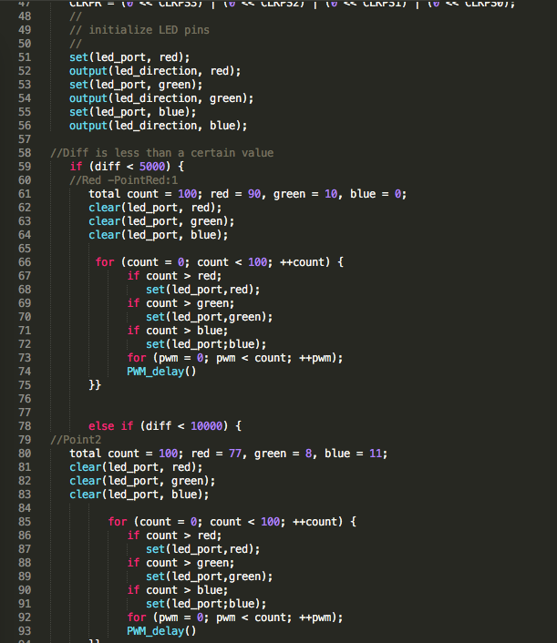
Gradient Lighting : Since a chess board is an 8x8 structure, I will have 8 main outputs from my RGB. I worked with Rob Hart to unpack thinking about these logic statements using if and else if statements, and possibilities of connecting this to the step response. Currently, what I will need to change within this code, are the values used for " diff"
 <
<
Step Response and RGB
In this particular bout of code, I connected my input and output. In the nature of spiral development, before I go forward and program in the gradients of color, I will use full colors of red, blue and green to test what values I should use in programming what to do in response to variable diff .
Asynchronous Serial Bus Communication
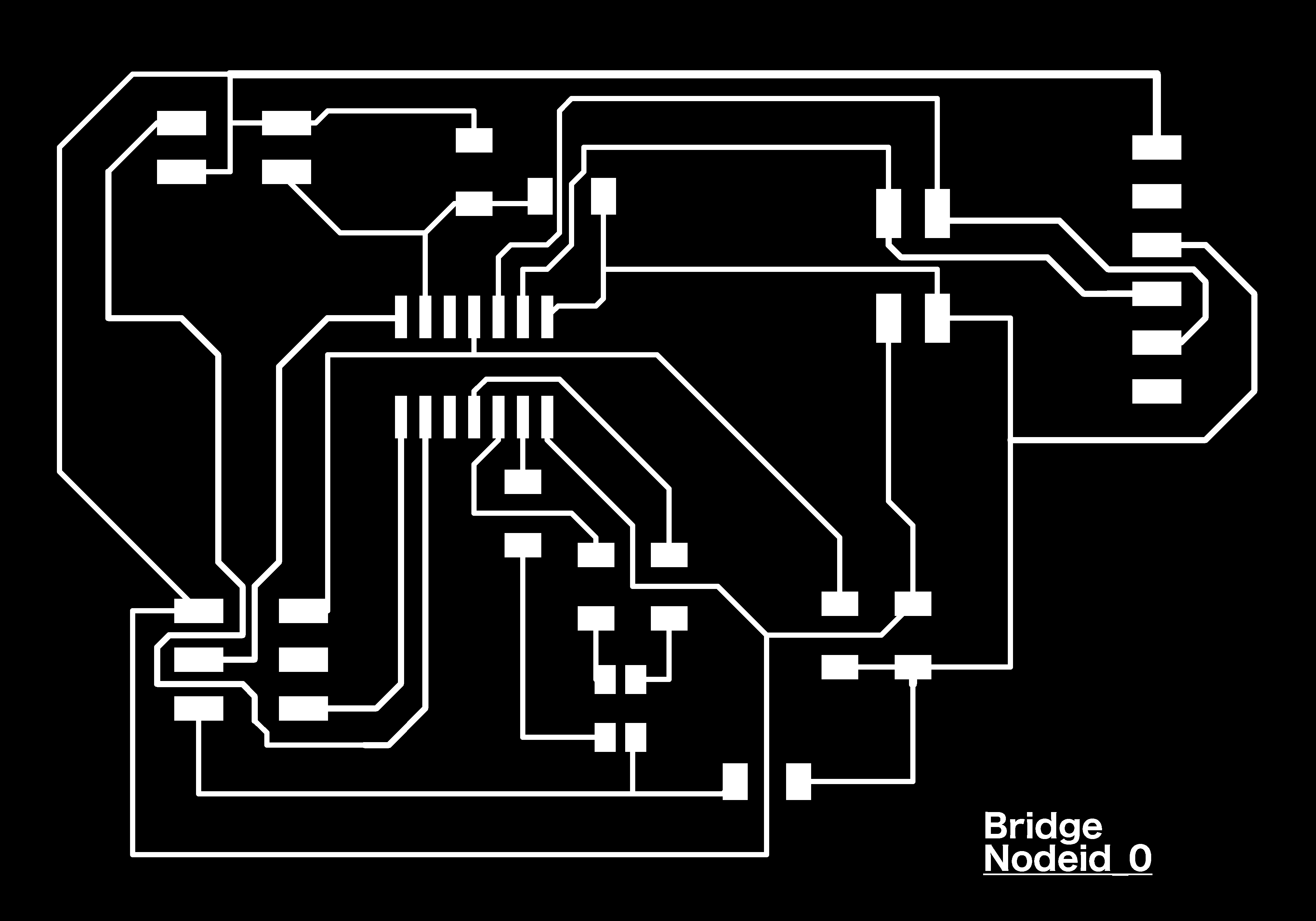
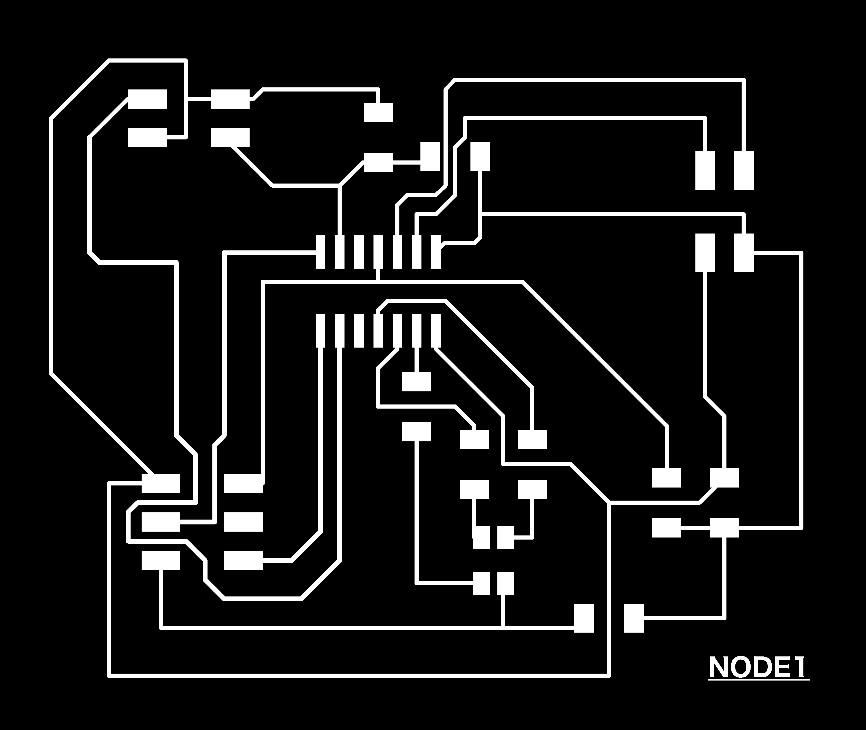
Through serial communication, I will use much of what Neil has used. In this iteration, it will be enough to just recognize my 8 boards: 1 Bridge, and 7 nodes. I will be working on modifying the code based on the microcontrollers. Perhaps the best use of doing this is to connect these boards in a way that to recognize if the circuitry of the boards are working as well as powering them through one main connector of the Bridge board.
My goal for the boards as it relates to serial bus communication, is for each board 1. To send recognition of their existence 2. Enter 3. Send value of the last diff (which in this later iteration could be used in a different way, but for now just to keep track in an external space) 4. Enter.
Some notes to keep in mind regarding code that will be useful for me down the line:
#include :refer to the libraries that the code is calling upon.
get char : to receive information
put char : to send some information out
put string : to put out a string of characters
flash : function to flash the LED once
node_id # : each of the node boards will hold the same code, the only thing being different is this node id. A means to keeping track of board's identity.
Baud Rate: Bits per second. 9600 bps is "standard". The higher, the faster the data is sent and received.
Parity: Low level error checking
Start | Data (chunk) | Parity | Stop : Frame of the information sent
1 | 5-9 | 0-1 | 1-2| : Bit size within the frame of information.
Through All of That...
So with all of that, I was able to develop a series of iterations of code that build upon each other.
1. hello.TxRxRGB.44.c : Step Response TxRx with basic RGB functions using defined diff variable
2. rgbgradient.44.c : Main that focuses on the specific function of RGB through the gradient of color in eight defined spaces. Of course, down the line, I need to define the eight diff threshold values to determine color.
3. hello.txrxRGBbus.44.c | hello.txrxRGBnode.44.c : Combines the serial communication for the bridge | node with hello.txrxrgb.44.c
4. NEXT : To develop an updated hello.txrxRGBbus.c | hello.txrxRGBnode.c that includes rgbgradient.44.c specifics.
Design -- Did I Fail?
So, after feeling relatively successful in this above unpacking, I felt better about going into this process of designing behind my paper schematics.
I went through the step by step process on Eagle, drawing nets, labeling them and connecting them. When it came to draw my traces and connect my components, I was able to focus much more on what my board was supposed to look like, rather than being lazy and assuming the software would read my mind and connect things together in the way I had on my paper. Overall, drawing the schematic out first on a sheet of paper, labeling it with the appropriate pins, etc. was super helpful. I even caught that I mislabelled my TISO and TOSI pins, by checking my traces using the show A6 command, which of course, I would not ever really pick up otherwise. Who knows how many mistakes of this nature I have made in the past and pushed me into spaces of unwanted misery.
Who knew that dedicating time to these foundational steps would be so important? Ha!
Electronics Updates
Code
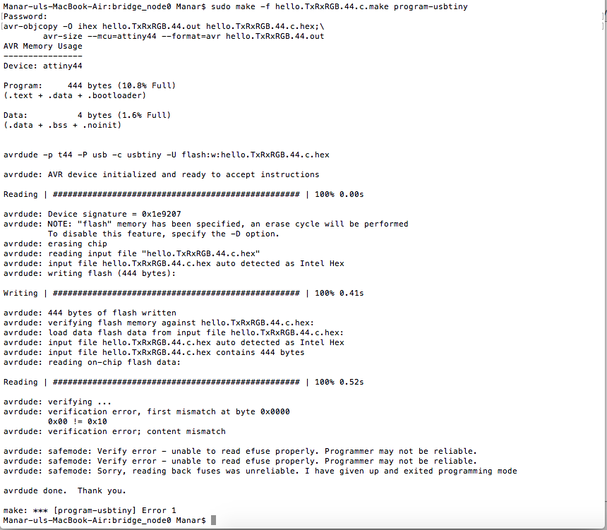
So, I definitely have some work to do regarding this. From the code I have captioned above to trying to flash it onto my boards, I received several error messages referencing some syntax errors and warnings that I defined certain variables and never used them in my function. Going through this process of debugging, I must say allowed me to sit with some of these lines of code (which felt untouchable at first--bc who knows if you'll accident break something by doing that). I definitely feel a lot of more comfortable with the process.
Electronics Design
4hours of Soldering, Debugging, Checking Connections, and more, and my my Bridge board was still not working. Why? There is a reason why none of my boards up until this point have worked. The progress I have made comes down to:
SCK to PA4
The reason why none of my boards have been connected is because the circuit board didn't have a clock function, or means to keep time. None of them have had this connection--and who am I to know that this was particularly necessary?
Back to Code, Back to Design
So after some rewiring and code amends (it's funny to see now the blatant errors I made in the above snippets of code), my circuit board was finally recognizable. Hallelujah! I first decided to test my RGB light to make sure that everything was working--and yay, it was! However, I realized a little later down the line that it's definitely best to check to ensure all of the colors are working.
I found out later that my green connection was not work. When I move to set or clear the green pin, my blue light changes. Red works fine. Blue does nothing. After checking my connections and designs, I came to see that the way that Eagle sets up your RGB and the way its presented in Neil's diagrams are in a very different order. So, essentially, my green light wasn't working because I had a 499K resistor attached to it, rather than the 1K that it needed to work.
Regarding my code, for some reason things worked up until a single point. I found out after about 30minutes of troubleshooting that there was an unnecessary "}" cutting stopping all of my directions in response to the step response my light action to work.
Step Response & Variable Diff
So I have a number of updates regarding Step Response. After deciding to remill | solder a new board and begin the process of beginning again with this whole code, I came to a realization of a number of things.
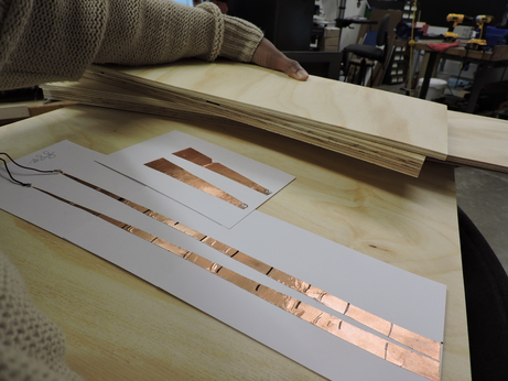
- The first point has to do with wanting to find the different diff values that would occur along the length of the board. So, I placed a piece of copper on the bottom of a piece and began tests out values, too big too small, until I landed onto the turning point of the value changing from one output to the other at the value 1023. I thought, SCORE! I was on a role, one down, 5 to go. (The first and last squares would just be diff < __(last turning point value)_ ; diff > __(last turning point value)_). However, after talking with Joe and Miki, I came to realize that the copper was the perfect conductor for this circuit, and instead was closing it. Essentially, I had created a button. When connected, I would receive one input, and when separate another. It didn't really matter where in distance this piece of copper was.
So, I decided to instead go along with this idea of a button, create 8 buttons, that no longer would run down the length of each column, but run across, or perpendicular to each column (across each row). Each strip of copper would be assigned a color, and when the circuit closed, you would see a light show of sorts.
It makes me sad that this step response doesn't work in this way as Rob and I had initially hoped. With that in mind, I then turned to run python and see specifically what was going on up until 1023, and what sorts of materials might be used as a suitable conductor, instead of simply copper.
Serial Communications with Python
I found two useful student pages to get python up and running: One & Two. There was no tutorial online or space documented to show how to start this process--who would have thought that the archives of previous students would be this helpful? So, I installed Pyserial, created a Python File, configured my USB port, ensured that my code had correctly assigned its serial port outputs and pins.
Last but not least, to the suggestion of Miki, I downloaded CoolTerm so I could see in realtime the values that were being communicated from my PCB to my computer. I also learned a thing or two from him about how to read the messages sent through serial . We fiddled with CoolTerm and were able to see that the values were changing, and in fact using Hex to ASCII converter, I was beginning to understand things. Not enough to relay it back to you at the moment, but a bit more time and things would make sense. Thank goodness for Python.
Somehow I was able to open Python and see this visualization in realtime, using Neil's code. However, low and behold, the next day when I came back to this exact process|procedure, it wasn't working, of flat out even functioning. Even though, i was able to flash my circuitboards, both the bridge and the node, I couldn't open Python or CoolTime--my programmer wasn't even being recognized as a serial port. For about 4hours, I troubleshooted this issue, between visiting a number of websites to search for answer, to switching programmers, and even laptops, nothing was changing.
Serial Busing
And with that series in my spiral development not working, I wasn't able to move forward with serial busing communication between my currently existing bridge and node. In essence, I was moving blind in an unfamiliar territory, and definitely too late to begin unpacking this. Instead, I will use a network cable to power the eight different boards I will have. I shall get back to you with how that goes.
Final Updates
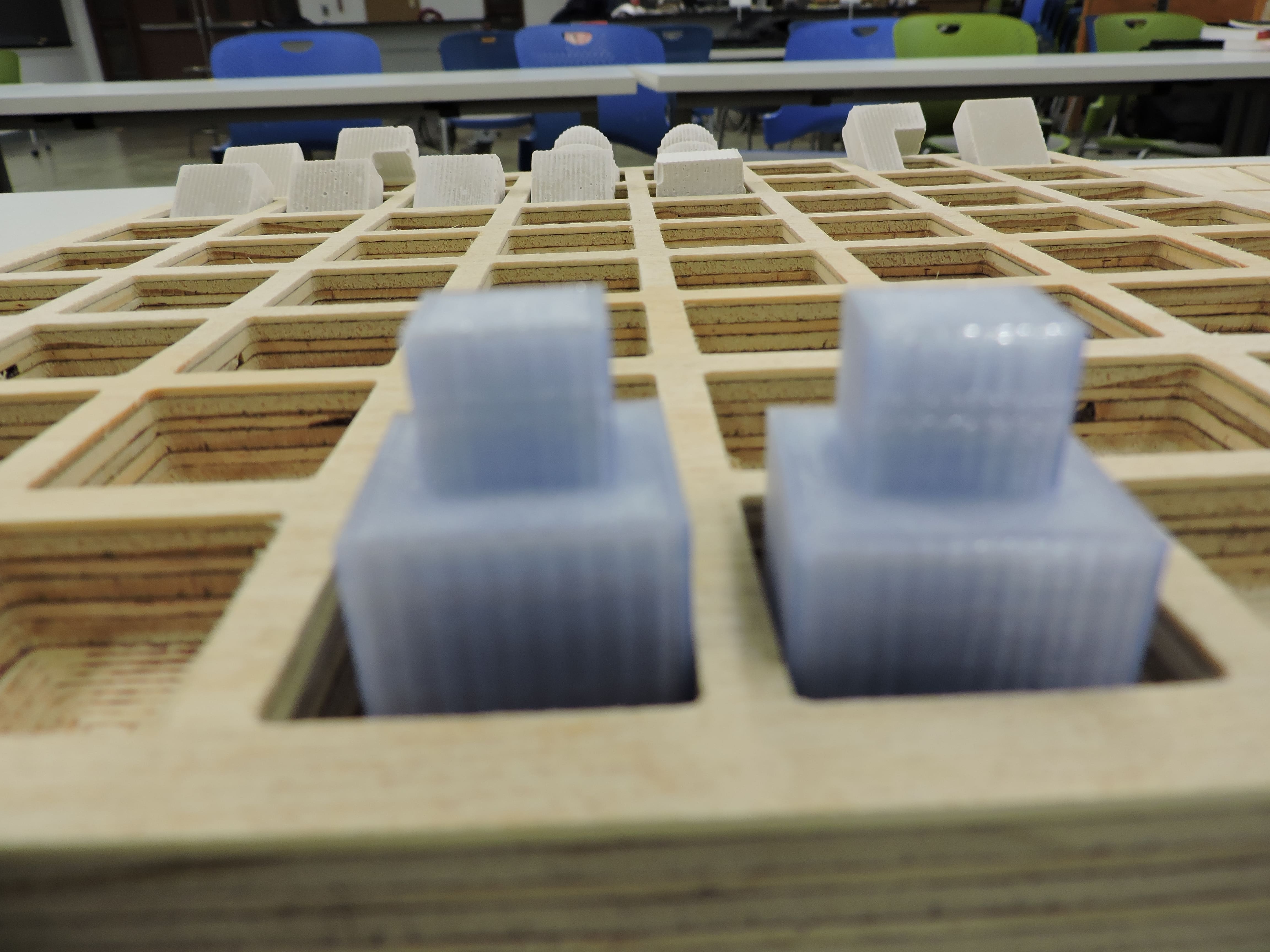
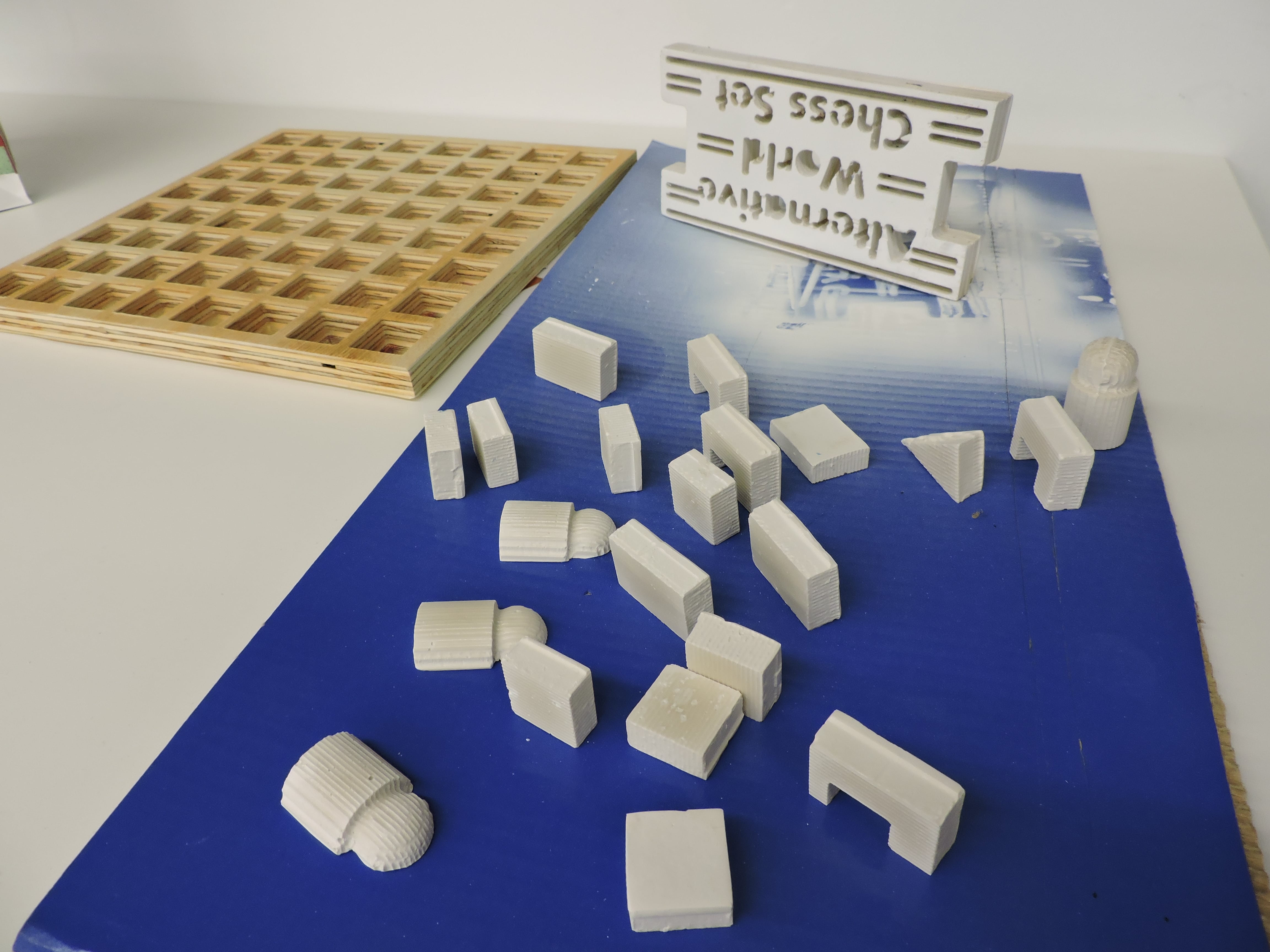
Chess Pieces
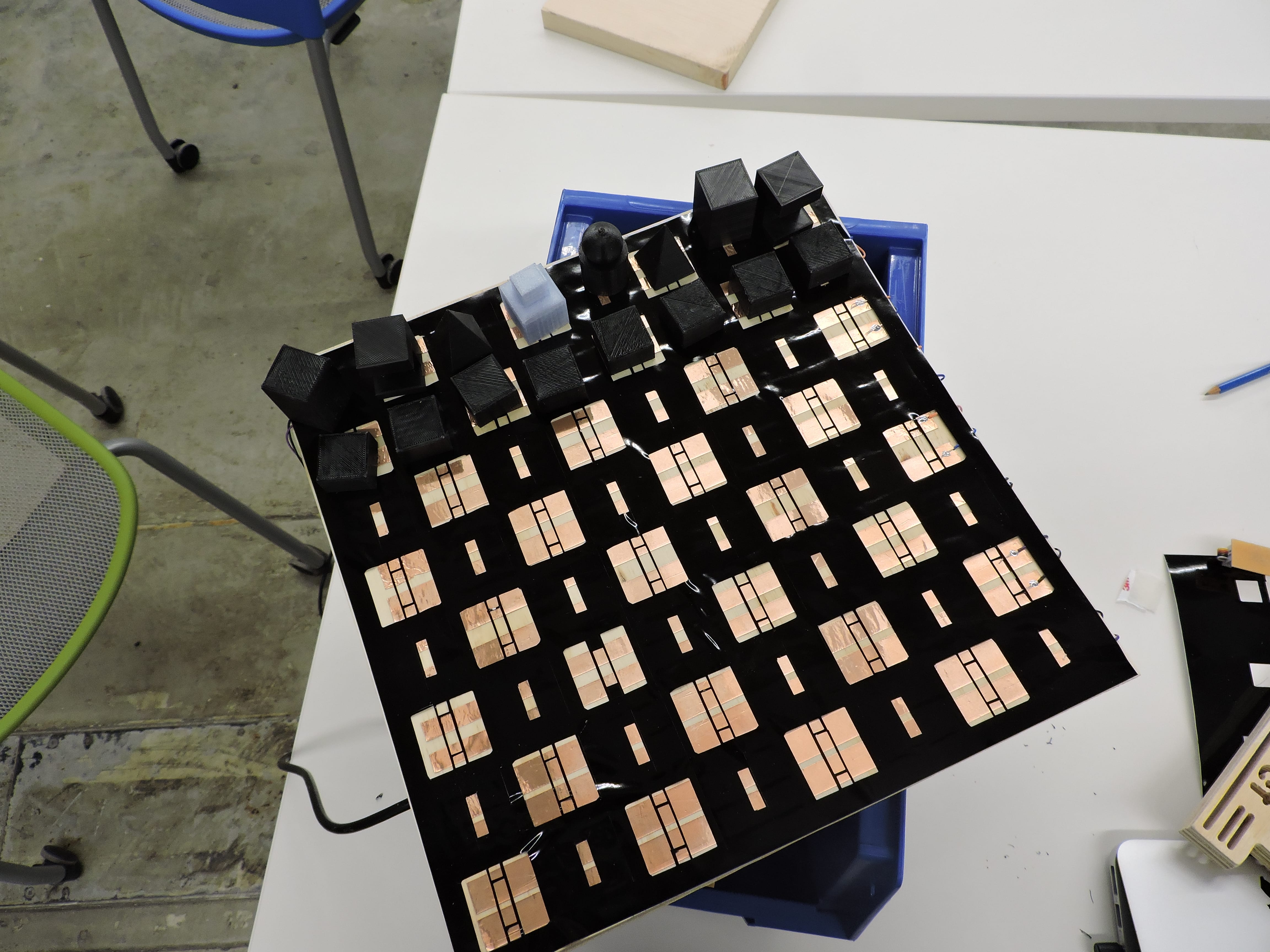
And so it goes, despite my initial plans, I ultimately created pieces--half Molded and Casted from DryStone and the other half 3D Printed. The backs of each of the pawns are .9*.9" pieces of copper. In the flat board, they are means to be facing downward as to create conductance across the board, and in the board with depth, they are meant to face the player, so they reach above the depth. I sprayed the finished pieces with
Each of these pieces are textured, so theoretically with the full working version of this board, you could also play in the dark. The lights giving away how close you are to the opponents. Generally, what I wanted to do was create a body of movement based on the movement of the pawns across the board. Each of the DryStone pieces were sprayed with a finishing coat to offer some longevity.

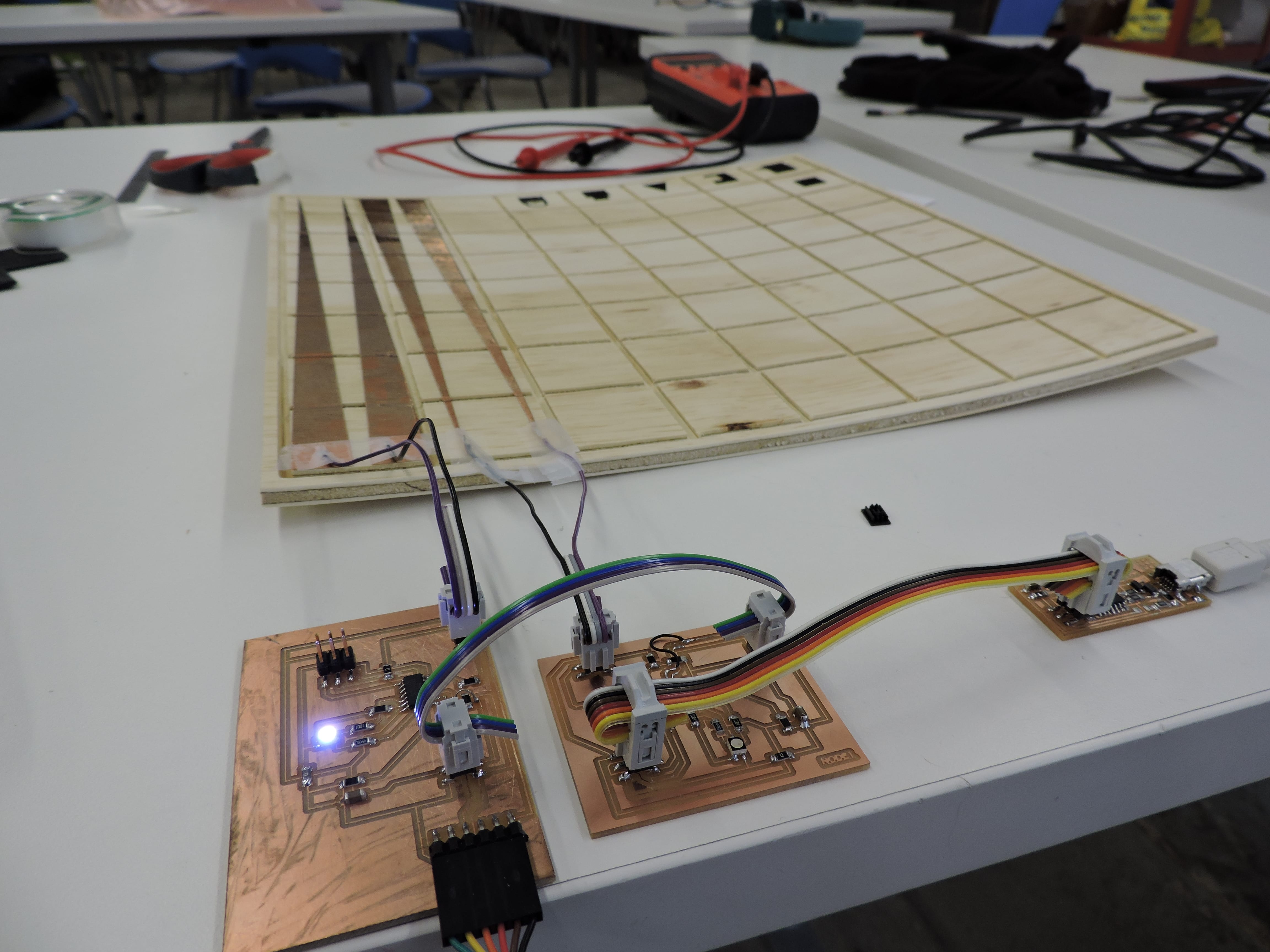
Board
I ultimately created two boards, a flat one (which was meant to be the underlay--aka home of electronics)and one with depth, the piece that the each chess piece would sit. As previously mentioned, the wood used to make these boards came from home depot. The flatter of the two pieces, the 1/4" was essentially warped and impacted the final products that I produced--namely, the flat chess board, and the side panels to my reflector box. Because of this, the two piece idea was temporarily scratched. Instead, the 5-6hour milled chess board (the one with depth) is currently more for show, and a means of transport for the rest of my pieces.
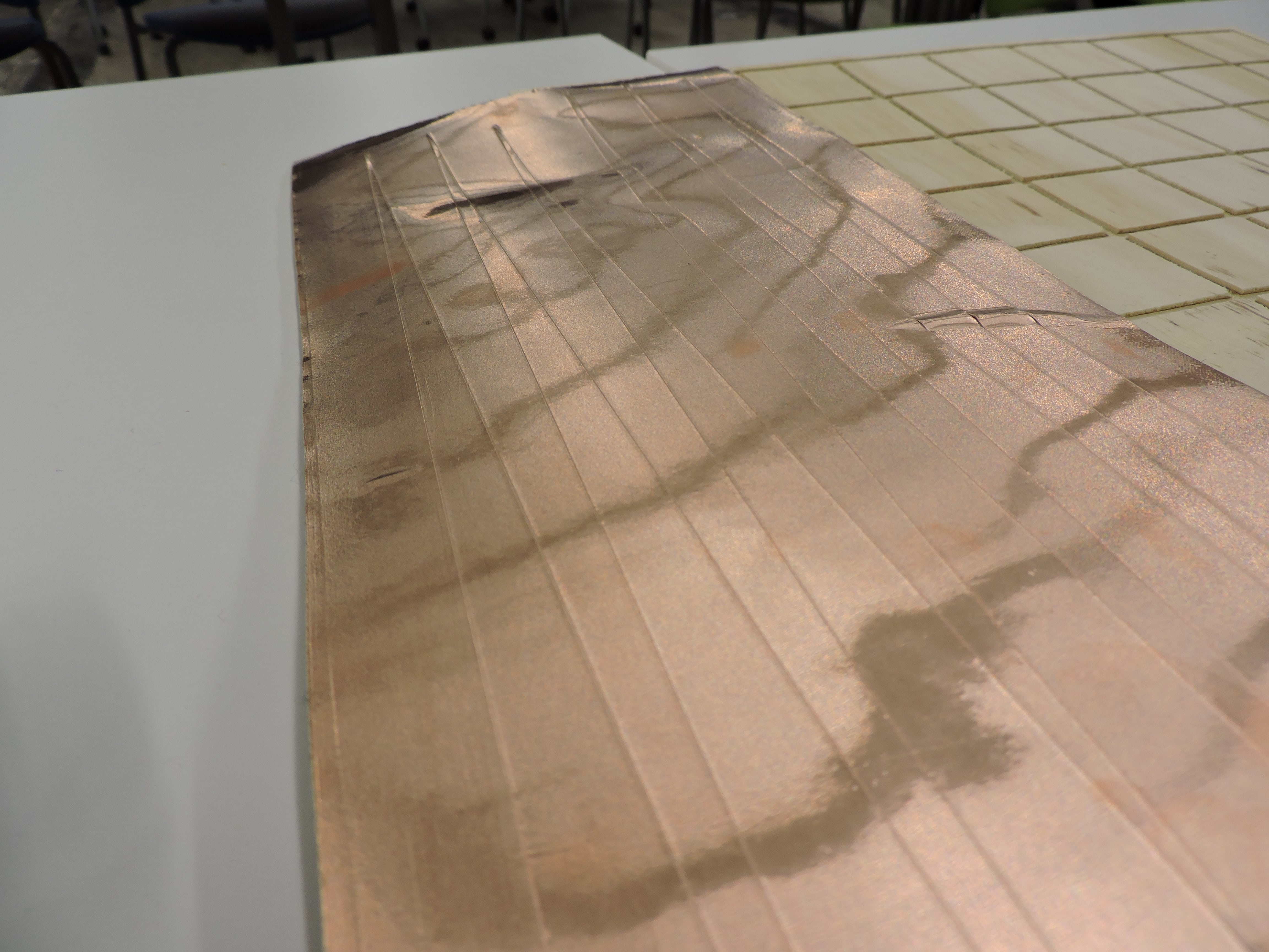
Regardless, I used the vinyl cutter to cut copper traces for each of my rows and then again the Roland to cut a trace overlay made of black vinyl. As you might have guessed, this is where the depth of the board was initially meant to be.


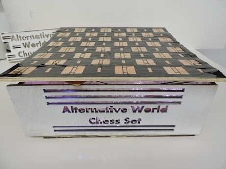
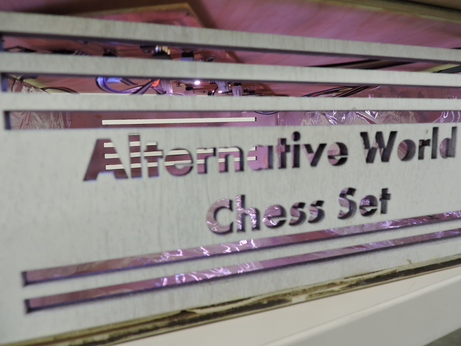
Reflector Box
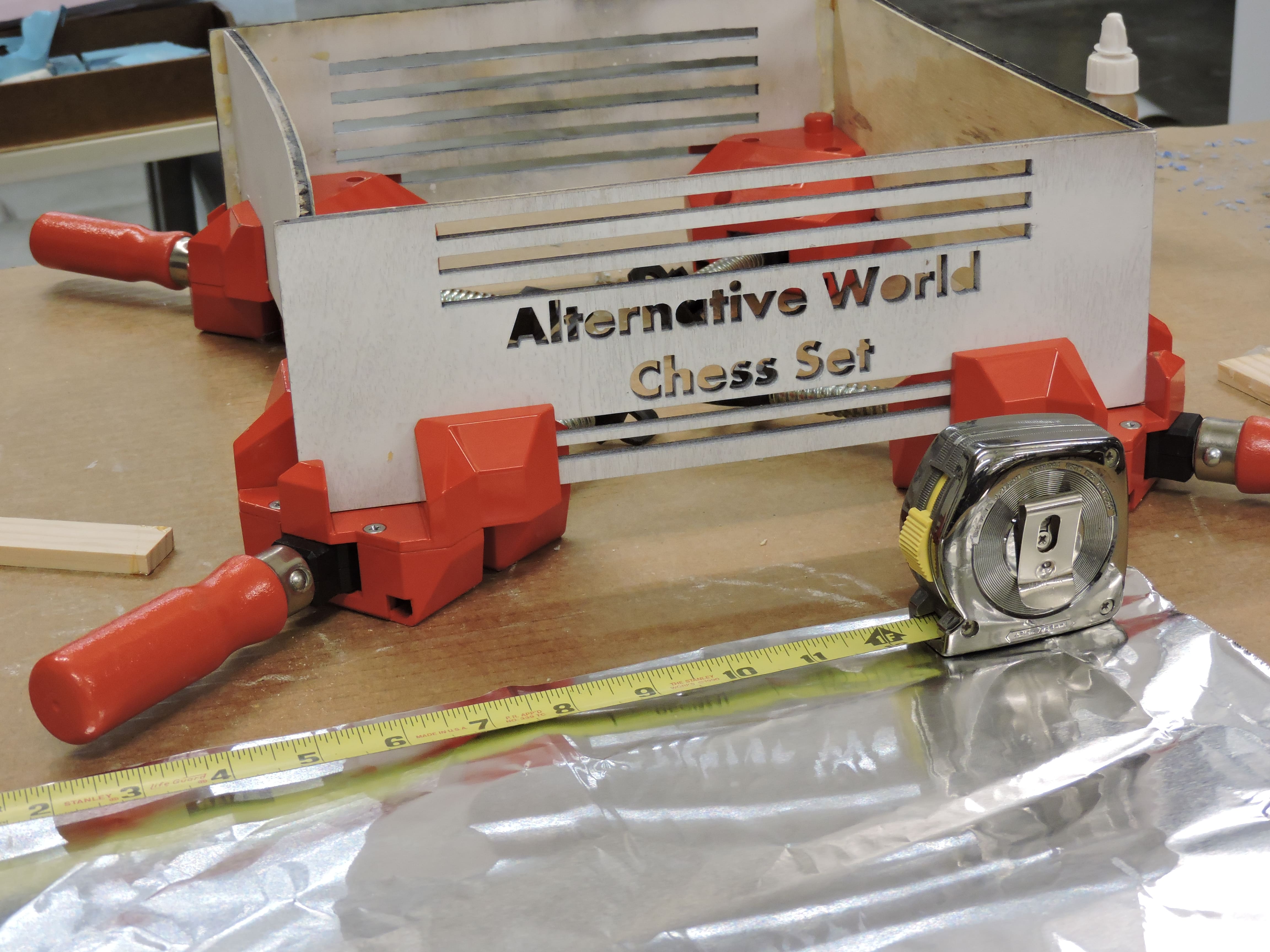
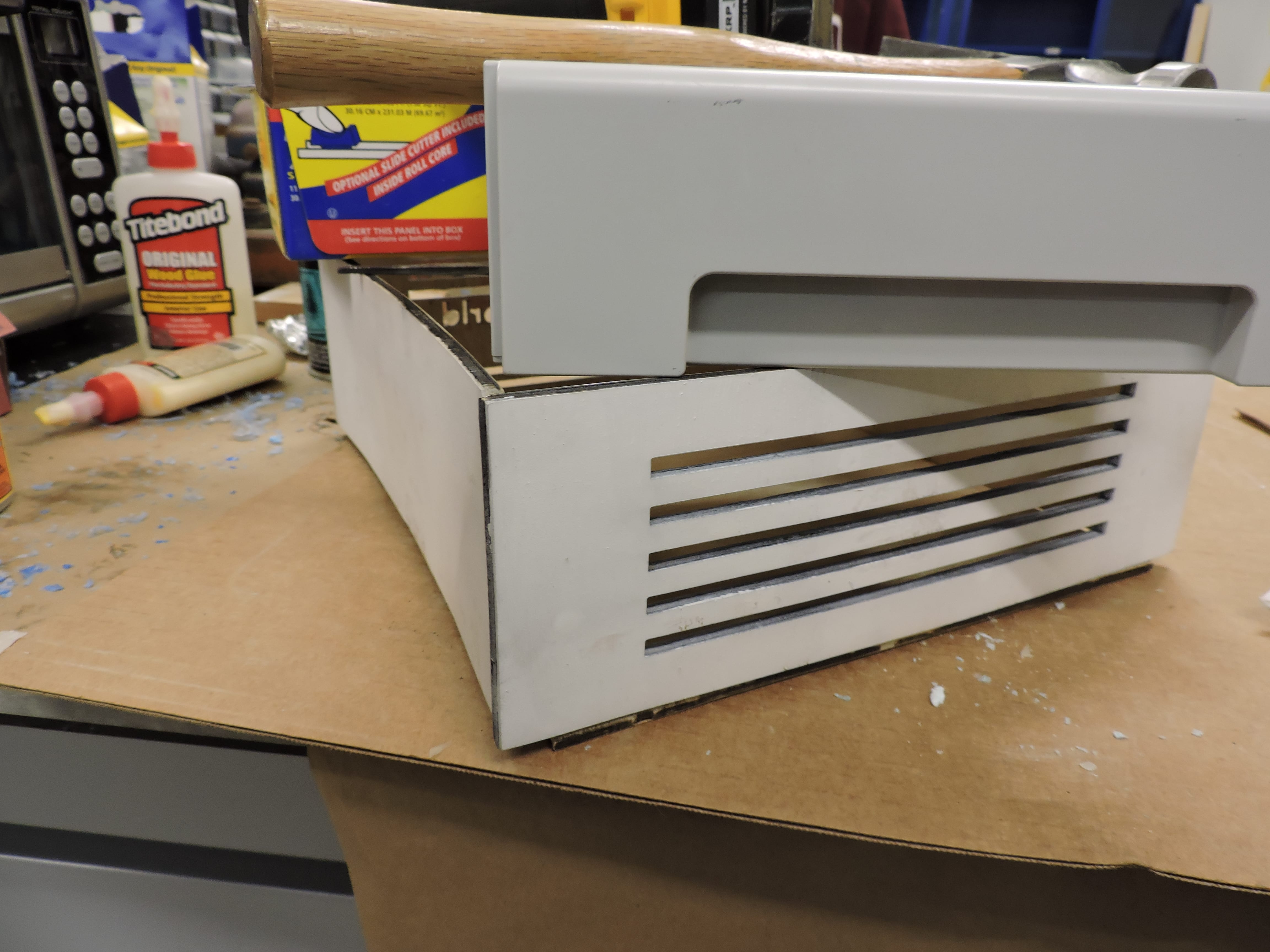
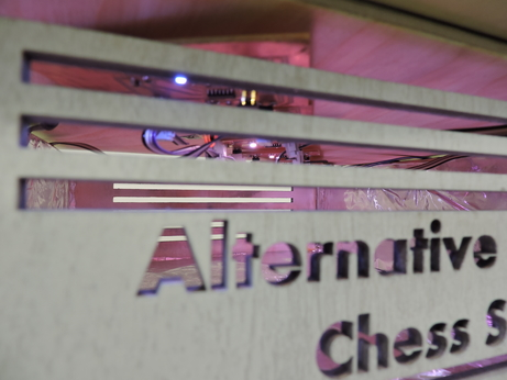
I developed a series of designs for this reflector box, and as time progressed, I had to make this more simple and use materials that I already had--so instead of an acrylic shelf with cross hatched shelves that would act to refract the light in multiple ways, I made a simple 12*12*4" box, whose bottom piece doesn't completely fit (the laser cutter temporarily broke, so I made do with what it gave me). Nonetheless, by using foil on the inside, the light will refract in a similar way (more similar that without it).
In efforts to make this box, I first used the Desktop Shopbot to mill from the wood scraps of my 3/4" wood. I had enough to make a 8*8*4 open press-fit box, but on my second piece, the 1/8" bit broke over a thickly packed piece of sawdust. I loaded it up again, and made sure the settings were in tune, and for a reason I don't know (there was enough room for the stopover, no sawdust there--I placed the vacuum nozzle overhead, and it wasn't going obviously too slow or fast), the bit broke again. So, I paused and came back another day.
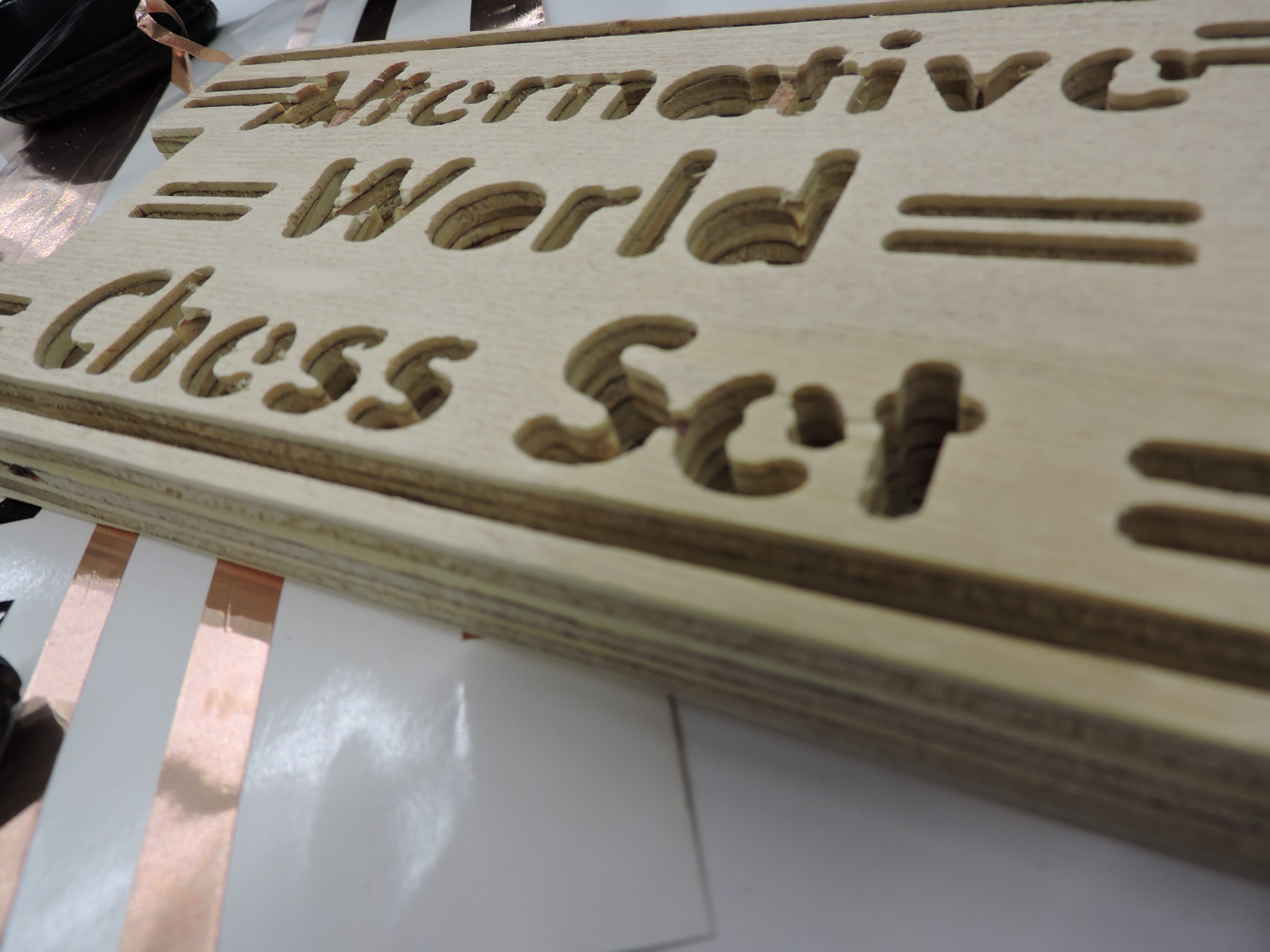
I ultimately used the laser cut, which turned out a billion times better -- especially for my lettering, to cut my wood to size. Using Daniel's corner clamps, Wood & Gorilla glue, I was able to secure my slightly warped pieces of wood to create something aesthetically decent. Each of the boards was sprayed with Gesso Primer Spray Paint, and the inside lined with Reynold's Foil.
Electronics
I'm happy to say that I was able to uncover exactly what happened for those several days where I couldn't access the python script. A learning moment, to be precise--the FTDI pin header is what is Transmitting and Receiving the serial script, not the programmer. It just didn't seem to connect with me until I sat down with several someone else’s to unpack this.
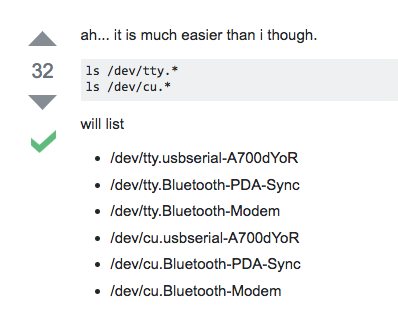
By following this advice, and seeing usbserial, I automatically took that to by my USB programmer. Mistaken, I realized I was.
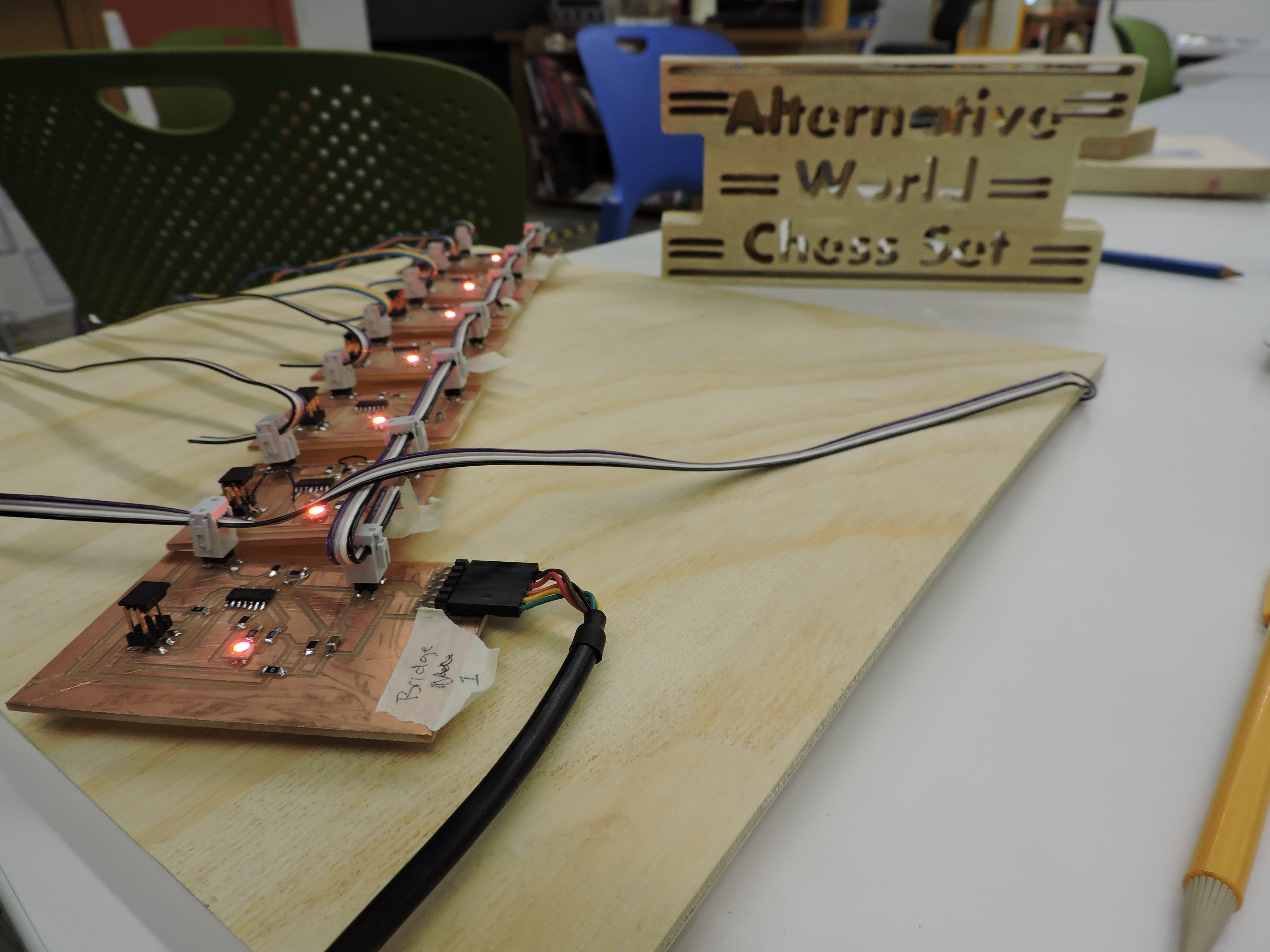
Ultimately, I have a total of 7 PCB's, 6 which would theoretically act as nodes, and the main bridge.
I was able to ensure that each 7 of my circuit boards were functioning as they should be. Although, I still was unable to work within the realm of networking communications, to get the programmers to talk to each other and move in unison, they currently function as independent bodies, connected to produce a single dance of light movement over time.
In the next iteration of this project, it would be interesting for the board to operate as a collective entity. Perhaps, to create specific sensors for each position on the board and sending the information to a program, where I could simulate the happenings through other mediums.
Overall
Project Presentation - FAQs
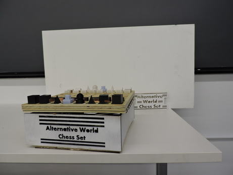
What is it?
Alternative World Chess Set is a chess board in the traditional sense, with 16 main pieces per player. What makes this an alternative world is the political framework which undergirds the existence of this game--specifically imposing a new value for the position of each pawn.
What does it do?
In this iteration, this chess board responds to the movement of the pawn with a series of light displays. Once turned on, the LEDs will glow white, however once pieces are placed in position, the light show begins. As pawns begin to move across the board, the lights and shades of each changes.
Who's done what beforehand?
I'm pretty certain that no-one has done this before--however, there are a variety of very interesting chess boards out there.
What did you design?
I used Fusion360, Eagle, Paint, GIMP, and my oh-so handy paper and pen to design everything. Inspiration for shapes of each piece and the chess board itself was taken from Bauhaus movement.
What materials and components were used?
Chess Pieces: Wax, Moldstar | Oomoo, DryStone, PLA Filament (Black | Clear), Finishing Spray
Chess Board: 3/4" and 1/4" Plywood, Copper Sheet, Black Vinyl
Reflector Box: 1/4" Plywood, Tin Foil, Wood Glue, Gorilla Glue, Primer Spraypaint
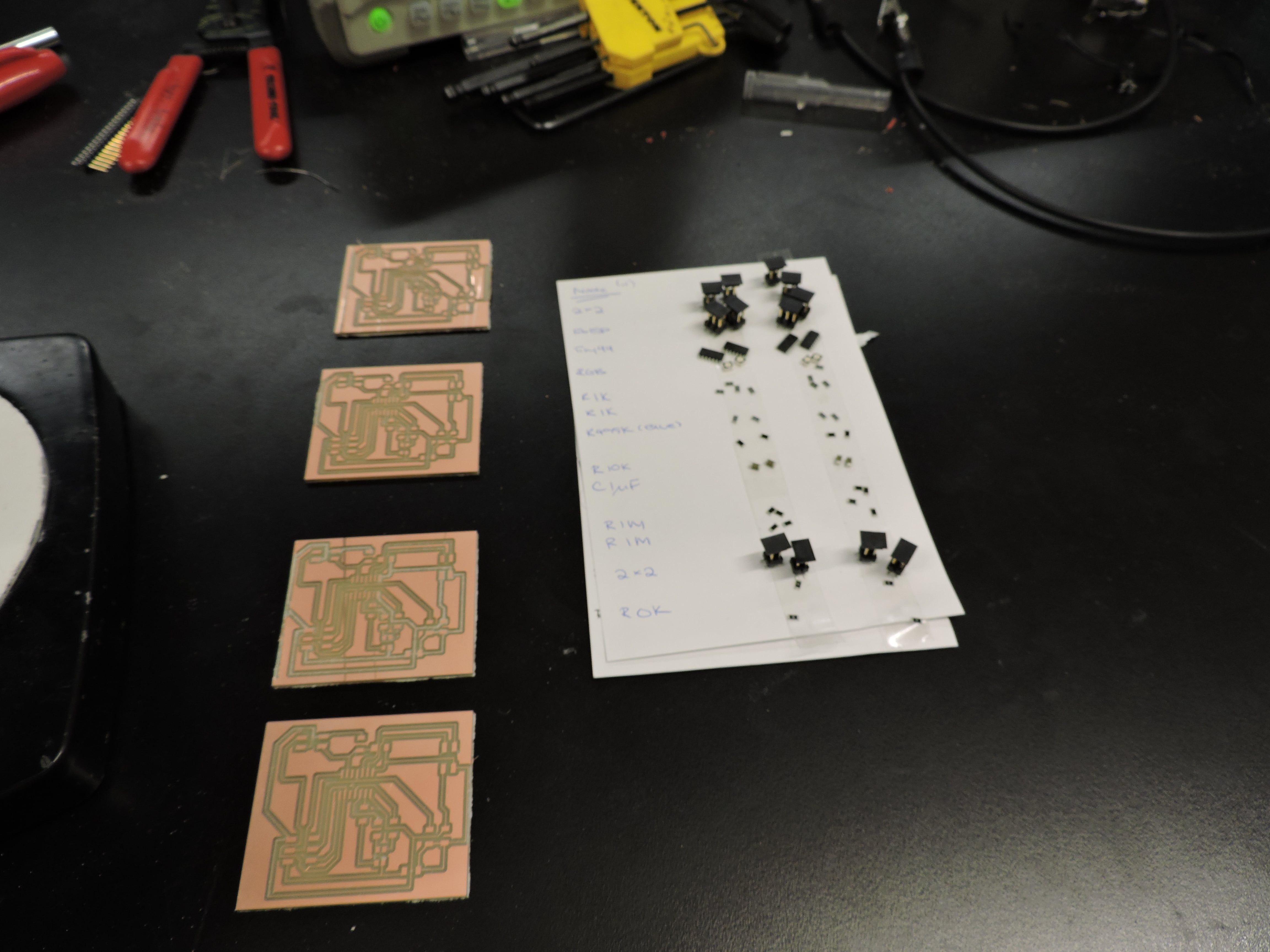
PCBs: Copper Base, 2 1M R (step response), 2 1K | 1 499K R (RGB LED), 1 2x2 header (Step Response), 1 2x2 or FTDI pin (Serial Busing), 1 3x2 header (FabISP), 1 10K R | 1 1uF C (Limits current), 1 ATtiny44 (microcontroller)
Connecting: Cable Headers, Cables, Velcro, Double Sided Tape
Where did they come from?
Most of these items and components came from the lab. Otherwise, I purchased the wood from Home Depot, the spray paint/finishing spray from Blick.
How much did they cost?
Wood came out to a total of $16, Finishing Spray $11, Gesso White Primer $10 (plus tax)
What parts and systems were made?
All of these pieces were made from scratch--well of course, except for components.
What processes were used?
Input: Step Response
Output: RGB LED
What questions were answered?
Mainly, my questions revolved around me developing and finishing a finished project, while actually understanding what it is that I was doing. This was a great starter project to begin to think about creating a finished item while integrating most of these weekly lessons.
Generally, I found myself unaware of the importance of each individual electronic component. Between using someone else's design and designing for yourself, and going through the process and route that current takes through your PCB was particularly helpful--additionally, drawing schematics by hand as references, rather than through Eagle.
How was it evaluated?
Q: Does it work?
A: Yep!
Q: Do you understand how it works?
A: Yep--just scroll upward and read.
Q: What has this process of creation done for your learning?
A: A lot. Just scroll upward and read.
Q: How would you think about building this out moving on?
A: Again, scroll upward and read. From Serial Communications to Bluetooth, to simply not warped wood, there's a fair share.
What are the implications?
To put it lightly, I started with a general college physics background (6 years removed) and no fabrication skills to start. Knowing myself, there's no way what I created couldn't have some narrative, some relevance, some use--and while a chess board is a purely practical thing to have, its political statement--at least, I'd like to think--is a means for me to address the world, even in this particularly insular way.