Final Project: AN INVISIBLE FORM
Week 01-xx | How to Make (Almost) Anything | MIT Media Lab | Fall 2016
IDEA: CONSTRUCTED INVISIBLES
This is a working prototype as part of my MDes thesis at the GSD next semester about sculpting airflow. We design visible forms. We understand the built environments from geometry, pattern, texture, sound, and lots of other elements that we perceive. I intend to take a step in understanding ways to articulate invisible forms in a similar vocabulary as those visible ones- points, lines, surfaces, etc.
In this project I decided to work with heat and motion as generating forms of flow. Heat: creates difference in refraction index and base structure of the form; Motion: sculpts the form with other objects based on their aerodynamic properties, speeds, trajectories.
List of tasks:
1. An array of tiny heat coils mapped onto a 3D form- a programmable heat form;
2. Stepper motor control the spinning motion of this 3D object;
3. A viewing screen;(TBD)
4. An input system- one wire bus temperature sensing;(TBD)
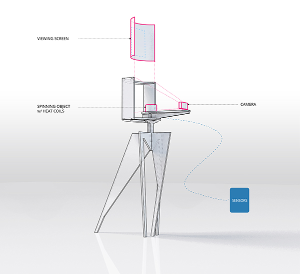
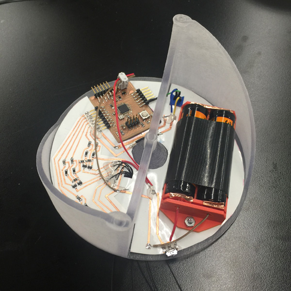
5. A designed object acts as a "fan", and integrates the electronics and other components;
6. A "big" stand that hold together the fan, screen, input system and other elements;
7. Tests with Schlieren imaging setup;
8.
PART A: HEAT COIL CIRCUIT
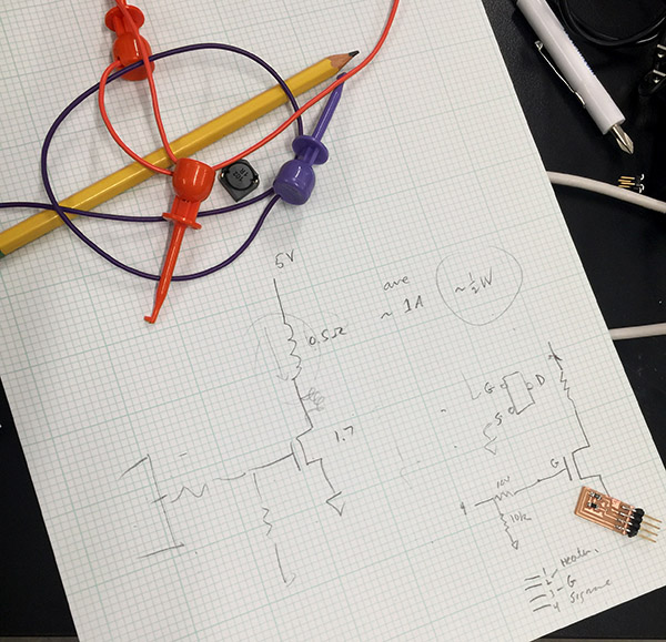
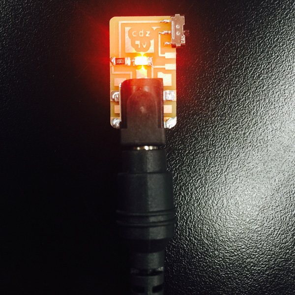
Starting output week, I worked on putting together the circuit of a series of heat coils. For the initial tests I used 0.5mm nichrome heat wire, and created a programmable heat painting piece:
Working with Rob on designing the circuit:
Testing process:
Modified for final:
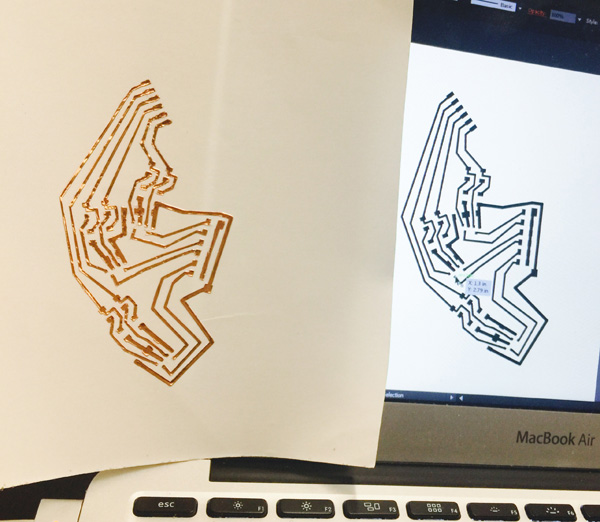
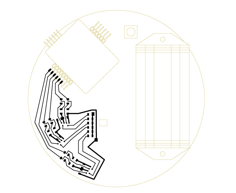
In order to pack all the circuit onto the object rotating with stepper motor, I decided to vinyl cut. And many failures later, I finally cut out one that had all the traces in place.
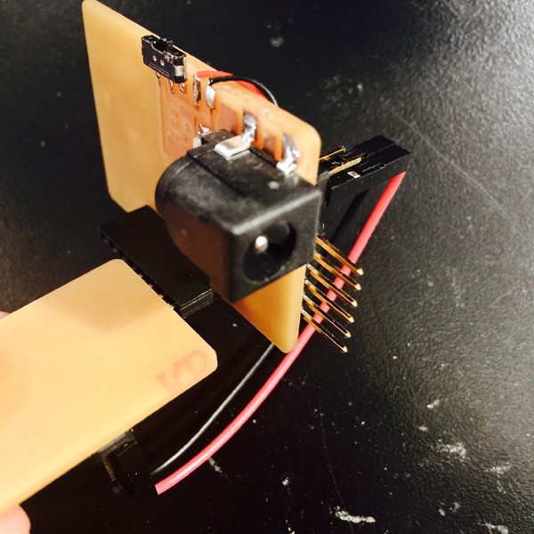
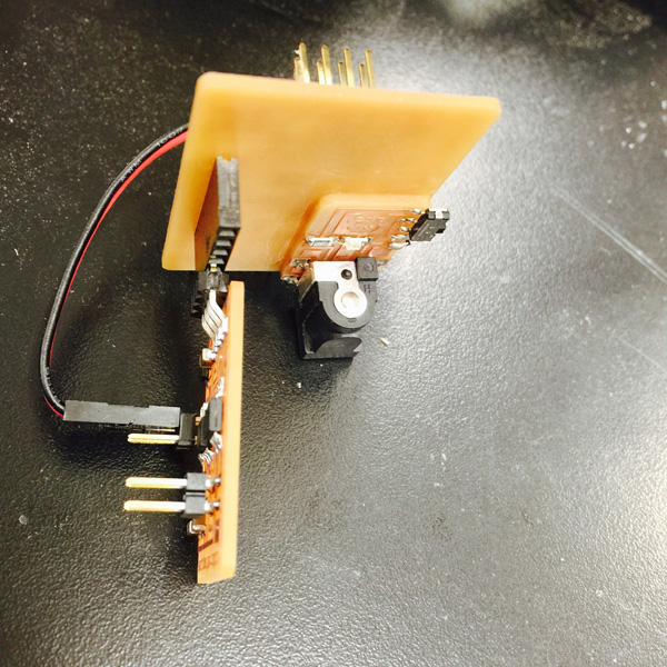
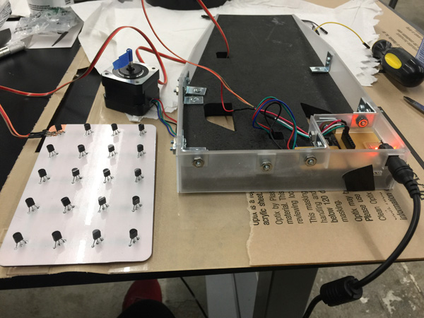
PART B: STEPPER MOTOER
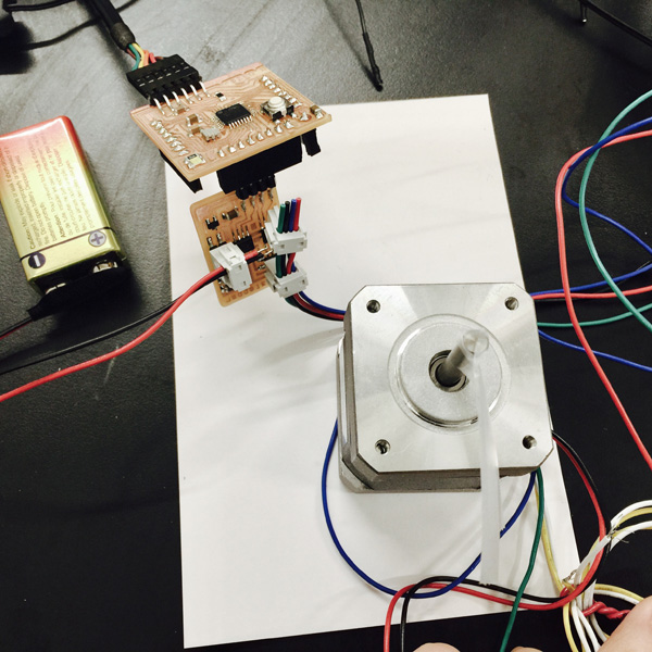
In output week, I also started on the stepper motor process with a breakout board and a Fabduino:
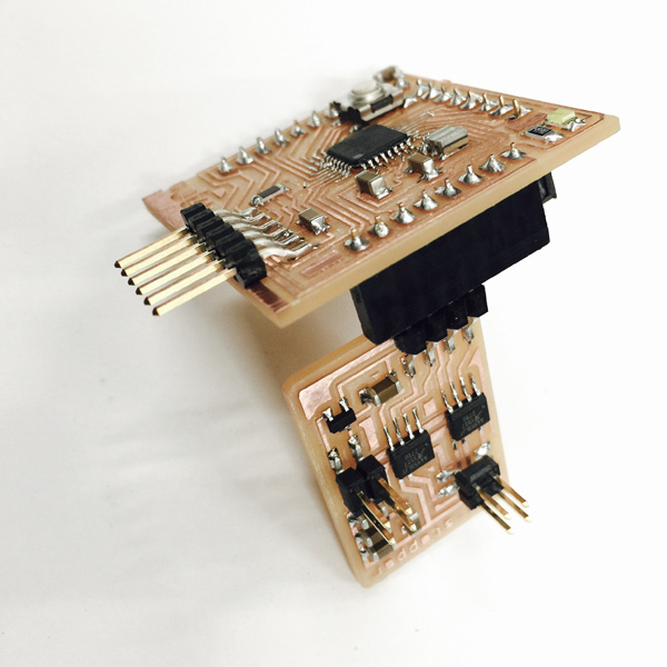

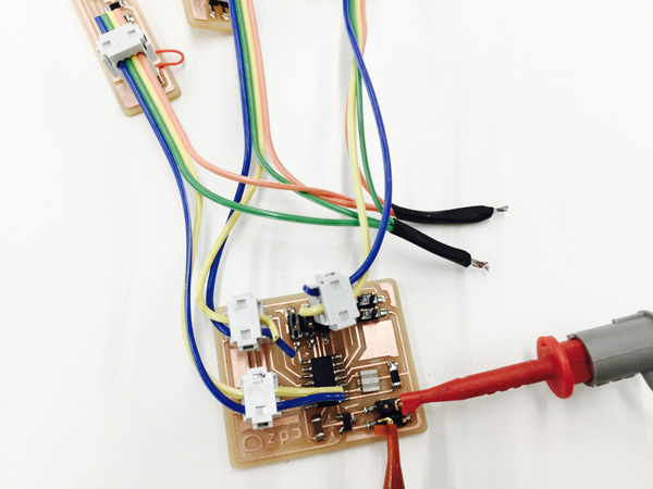
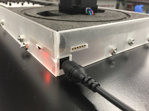
Adding a power jack breakout board to the final board with stepper motor and sensor:
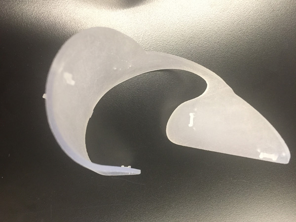
PART C: VIEWING SCREEN
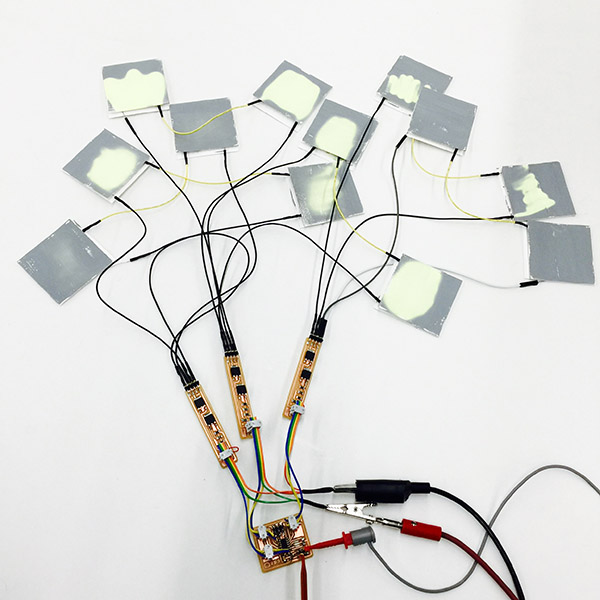
PART D: INPUT 2D HEAT PATTERN
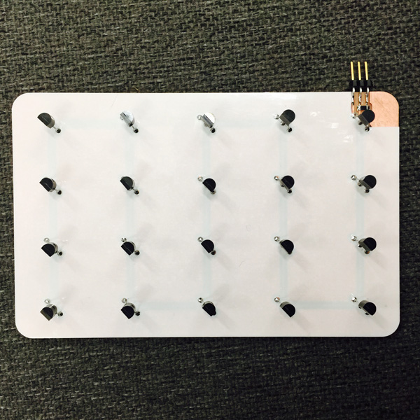
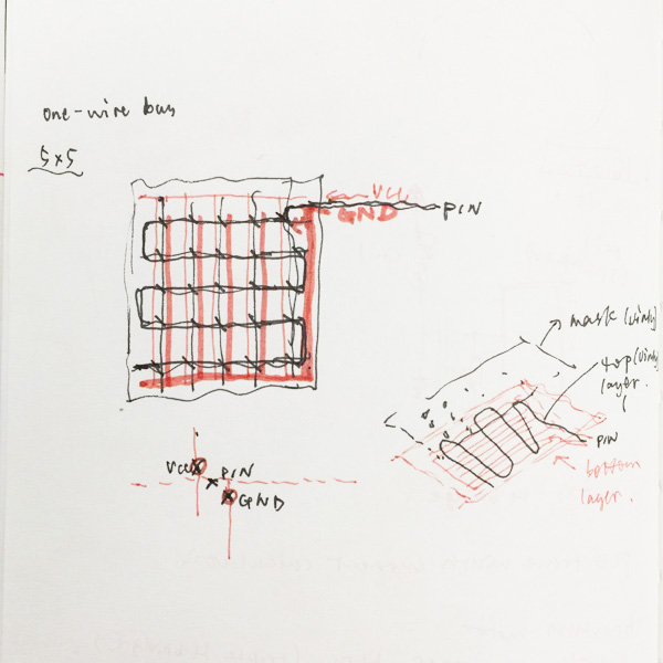
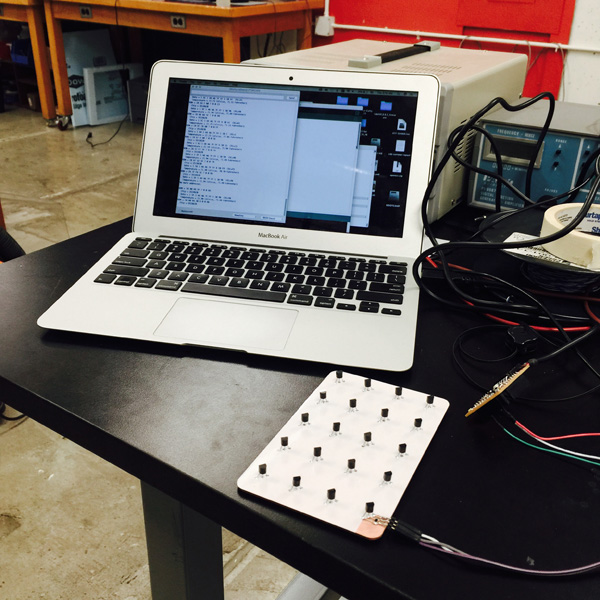
To create an interactive 2D heat pattern that would later be mapped onto 3D form, I looked into ways of sensing gradient heat pattern. 1-wire temperature sensors of Dallas Semiconductor's 1-Wire Protocol seemed to be the most feasible and interesting way after researching. I made my own sensing pad using DS18B20:
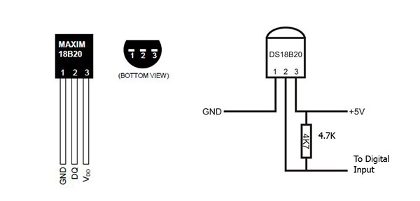
I looked through a list of references and tutorials about circuits and programming: https://www.hacktronics.com/Tutorials/arduino-1-wire-tutorial.html https://www.hacktronics.com/Tutorials/arduino-1-wire-address-finder.html
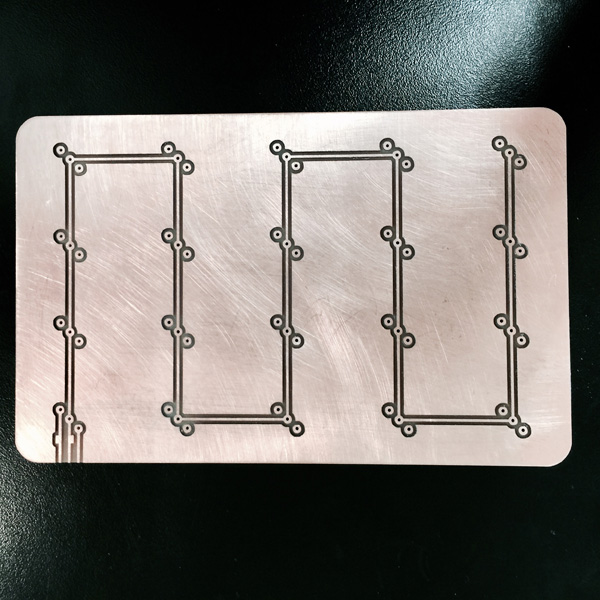
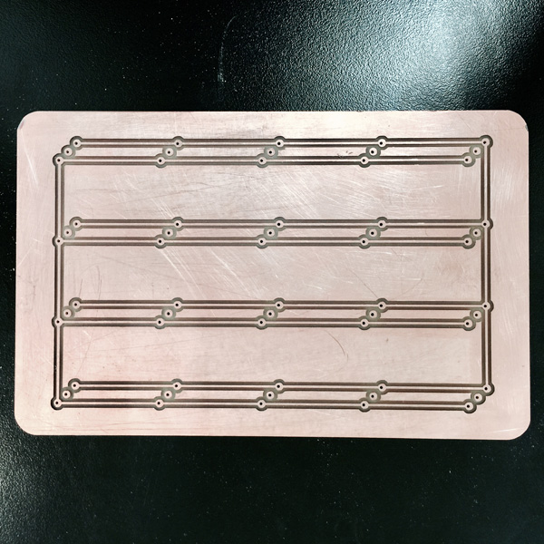
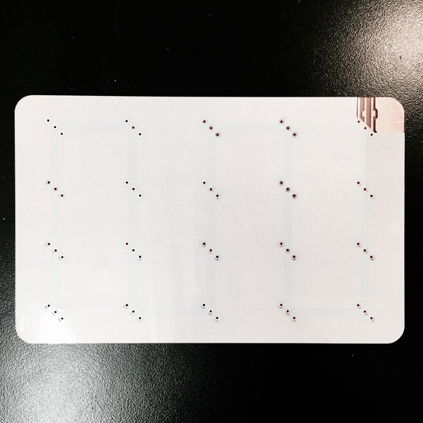
I used 20 DS18B20 sensor to create a 4x5 grid. Other things needed are an Arduino (in this case I used my Fabduino instead), and a 4.7k -ish pull up resistor (I used 5k because I couldn't find a 4.7k in the lab).
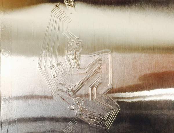
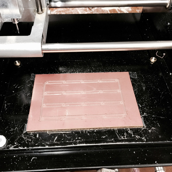
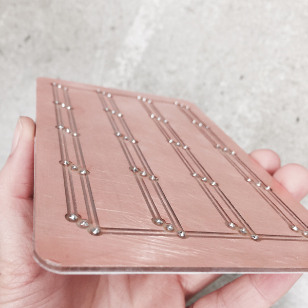
Milled the double sided board:
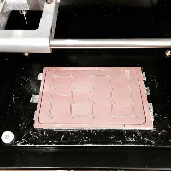
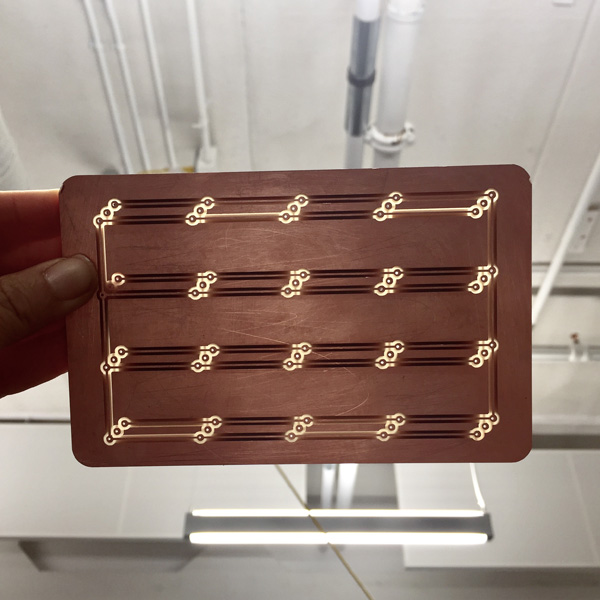
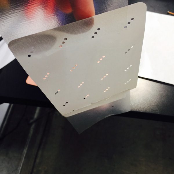
Then I vinly cut the epoxy mask as a thermal insulation so that the heat from the copper below won't interferer:
Soldering:
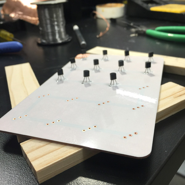
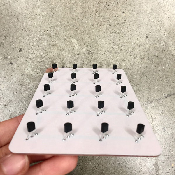
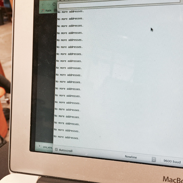
I first followed the power instructions on DS18B20 datasheet and used a external power and couldn't find the addresses of any sensor. Then I switched to the VCC and GND pin on Fabduino and it worked.
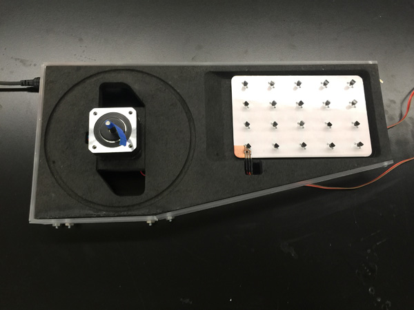
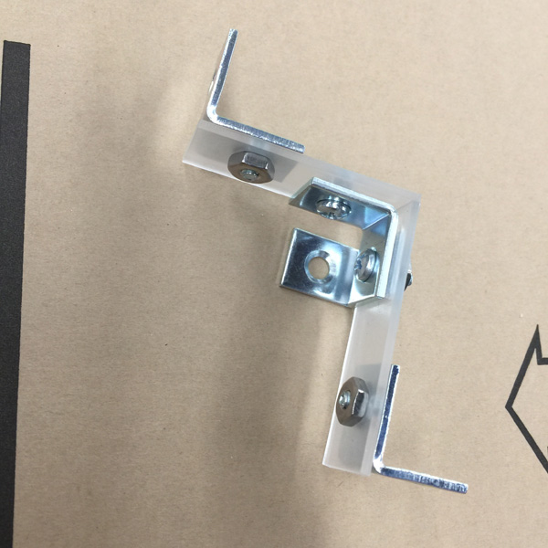
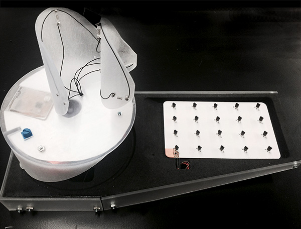
PART E: THE FAN
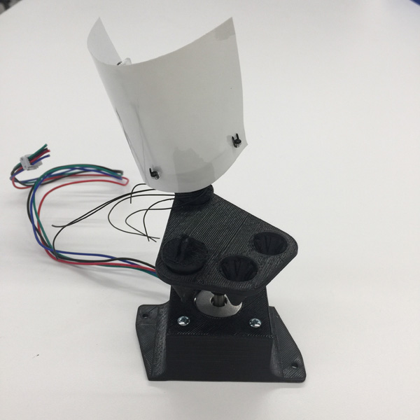
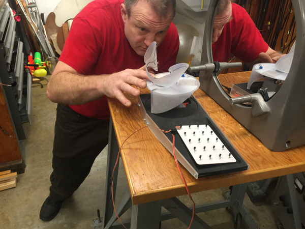
To start understanding what shape of blades and array of heat points would affect generating invisible forms, I began by putting together a first prototype for testing.
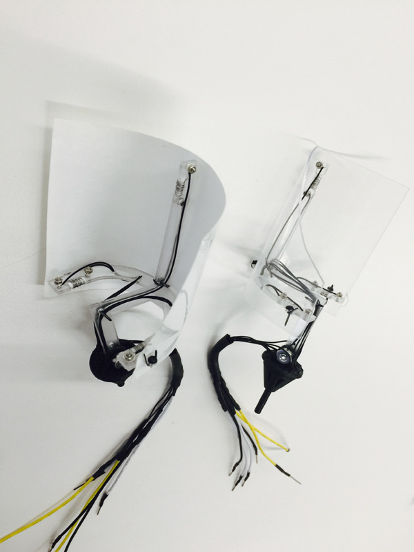
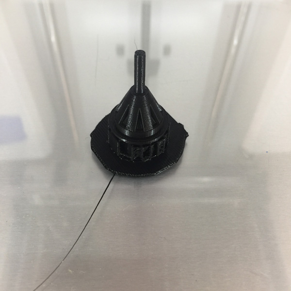
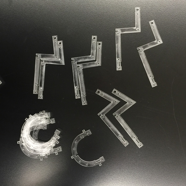
3d printed holding structure and lasercutted structure for blades.
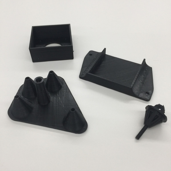
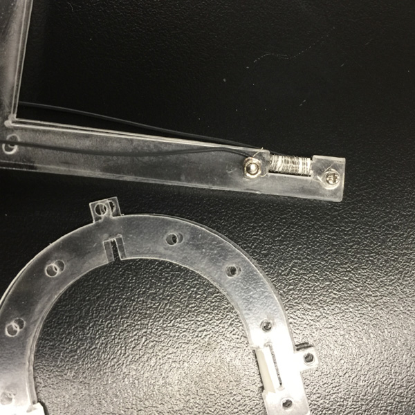
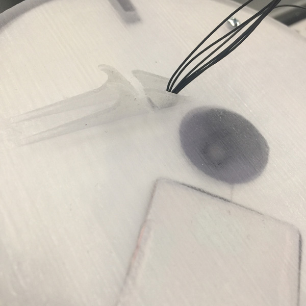
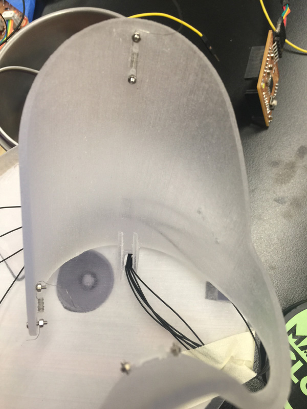
Because heat wire does not solder, I had to use mechanical connections to attach them with the circuit in 3D space. Due to the size of optical testing devices I limited the overall size and that made all the connections very small- barely could screw all of them with tiny screws by hand...
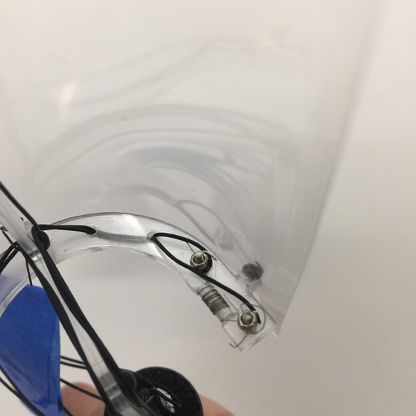
I made the blades at different angle to check if that result in any obvious difference in aerodynamic effects. The joints connecting blades and the rotating plate could precisely be positioned at 8 different angles also for testing purposes. And here is one piece sitting on base with motor housed in the holder.
Then, revising design for the next iteration.
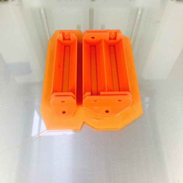
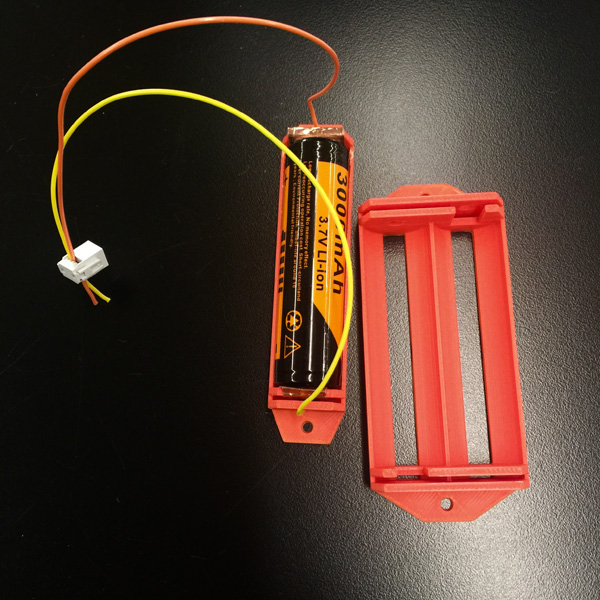
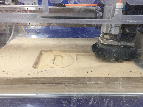
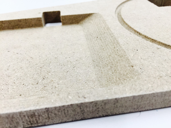
PART F: THE BASE
Milling MDF:
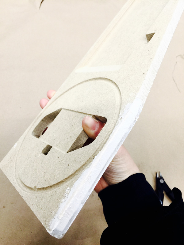
Holding electronics in place:
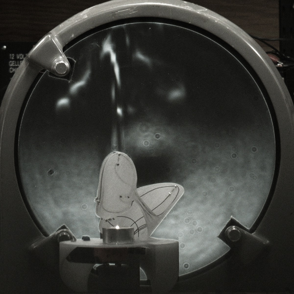
PART G: TESTING
First prototype testing with Schlieren optics setup:
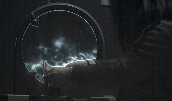
FANS prototype001 from catty dan zhang on Vimeo.
Yes... Needs some serious system integration... Also, the wireless hasn't been worked out so heat and motion are not synced yet. The rotation is quite small because the heat circuit boards are not being moved with the fan and that restrained the angle at this moment.
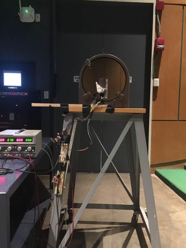
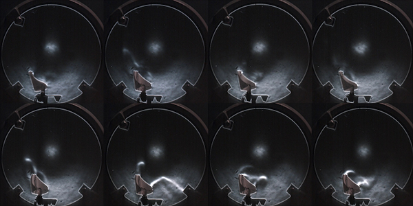
Second prototype testing with Schlieren optics setup: (Heat board ran into some problem earlier in the morning and Daniel suggested we test with candle in motion instead)
Thank you for reading!