Input Devices: TEMPERATURE BOARDS
Week 09 | How to Make (Almost) Anything | MIT Media Lab | Fall 2016
This week I learnt lots of things, one of them is what "at the bottom of a mountain" means. Anyway, I'm still far away from my goal of this week, which was to create a gradient temperature sensor as part of my final project- turning 2-d heat pattern to a 3d output heat frame with tiny heat coils arranged on a spinning device.
To do that I started my research in using multiple temperature sensors and found (Quantitative Two-Dimensional Temperature Measurements ) as a reference. I started by breaking down the steps:
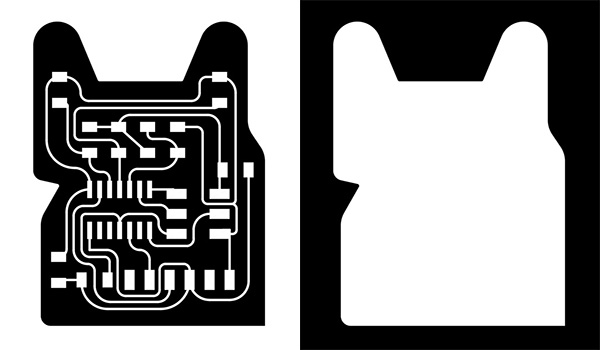
1. Make Neil's hello temperature board
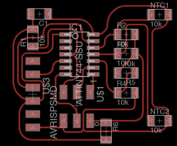
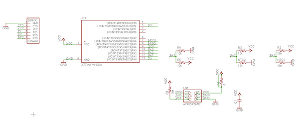
2. Design a board with a few NTC sensor with attiny44
3. Test both a simplified mode of sensing (non-bridge) with those sensor, and a One-Wire configuration.
4. Make some visualization
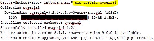
To summarize the achievement of the week: got python, pyserial to work; made three boards; understand much better with datasheet of attiny44 digital/analogue
And failure and for the future: the first board with attiny44 couldn't send serial correctly; failed to work with softwareSerial library on Arduino which I was originally to mainly use to start the process; need better understanding of differential input channel- the bridge did not function correctly on the new board.

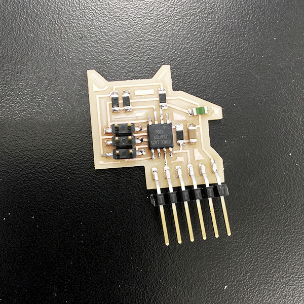
To begin with, I simply modified Neil's hello board.
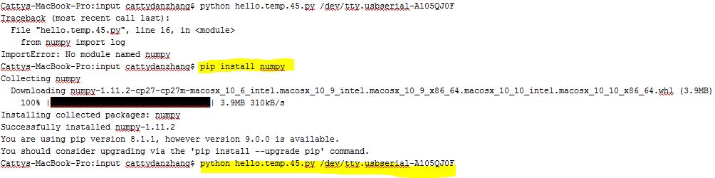
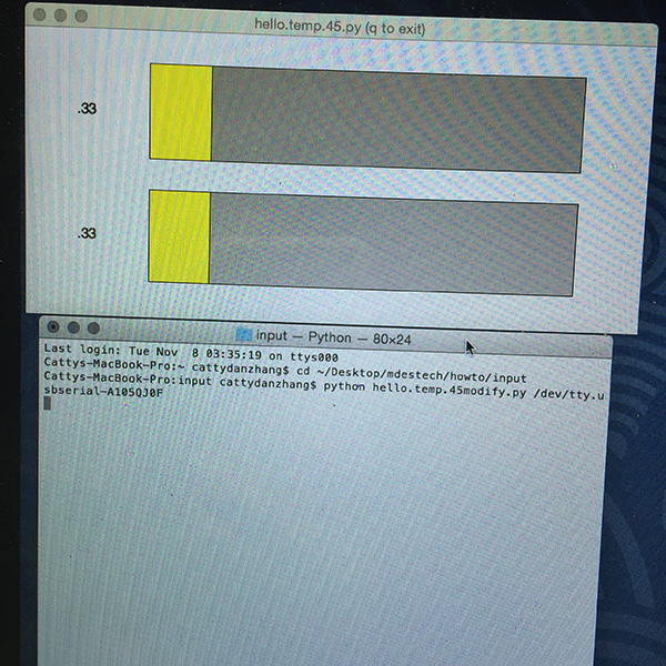
I was having some trouble making pyserial working on Python 3 so I ended up installing python2.7. I also needed to install numpy for the math operations Neil had for the temperature calculation.

Then I was playing with the python code, haven't gone very far on that:
Tried with processing code for visualization. This was modified from Nathan's example for rxtx board. It didn't seem to perform very well on this one. I haven't take a very close check what might be the problem yet.
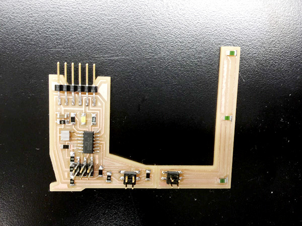
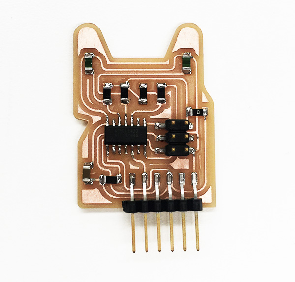
However, I thought I was ready to move on to start my test on multiple sensors. I designed the first board to be have a 2x2 header and could switch configurations of sensor arrangements.
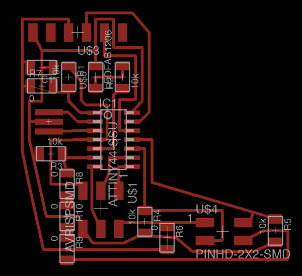

I had a LED originally connected to PB2 and three sensors on PA pins. This is not a bridge circuit- just a simple voltage divider to measure.
I modified Neil's code to adapted to 44 by changing ADMUX per datasheet, and serial port out to PA pins where RX connected to. And for unknown reason I couldn't do that without getting errors. I ended up cut the trace and wire PB2 to RX instead, and still get no correct serial reading. I then checked with CoolTerm and compared with that with hello board. On my designed board I kept getting random letters that does not make sense.
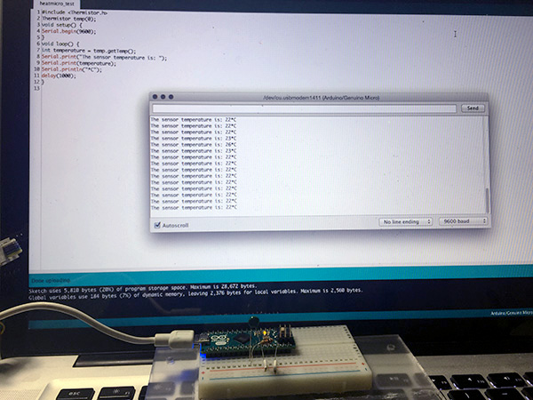
A tiny break: played with Arduino Micro
At this point I decided to simplify the design. The goal was to get it to work with attiny44, and working towards two sensors with a bridge circuit.
I tried program the board with both reading the bridge and not. Not quite correct yet-
I was also trying to modified the C code to send the read from both sensors, and haven't fully figured out.
Need to dive into AVR programming more but also need to make some plans on how to working towards final.
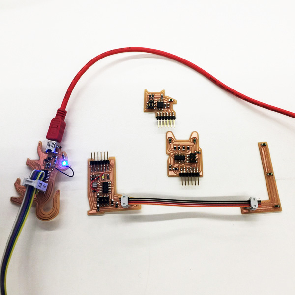
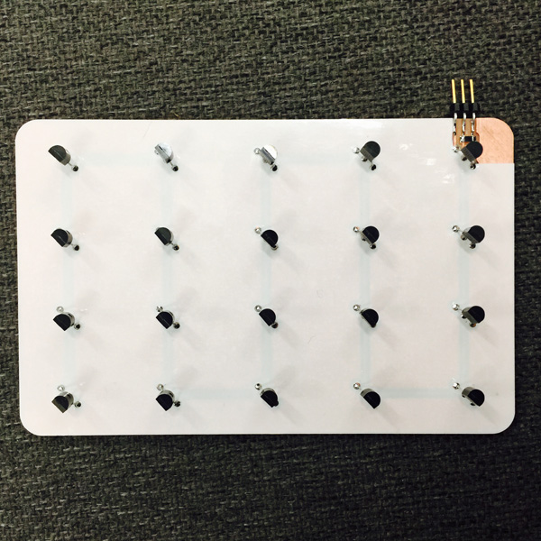
Updated: I made a sensor grid using one wire protocol for my input device for final project in Application Programming week. see Final Project for more details.
Thank you for reading!