Interface and Application Programming: HEAT PATTERN
Week 12 | How to Make (Almost) Anything | MIT Media Lab | Fall 2016
At the beginning of this week I made my new input device for my final project- a grid of heat sensors that captures a 2D temperature pattern. See Final Project for more detail of making the board and references. And then I used processing to start visualizing the gradient heat.

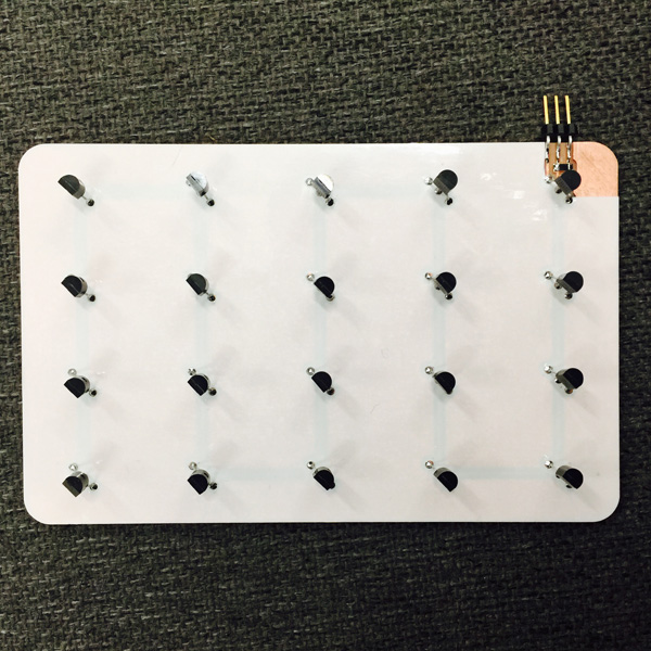
In theory each sensor on this one-wire bus has its own identity and the correct way of find out this information should be connect them individually and run a address finder program using Arduino IDE. I completely missed the individual tests step and soldered them all on to the board, so my addresses ended up being printed in serial monitor as a list of 20. I had no idea whether the order was same as their physical location on the wire. So I ended up spending some time applying heat to individual sensor and check which one has a change in value. By doing this I figure out an order of all the addresses that aligned with their order on the wire. Code below:
// This Fabduino sketch reads DS18B20 "1-Wire" digital
// temperature sensors.
// Tutorial:
// http://www.hacktronics.com/Tutorials/arduino-1-wire-tutorial.html

// modified by Catty Dan Zhang

#include <OneWire.h>
#include <DallasTemperature.h>

// Data wire is plugged into pin 10 on the Fabduino
#define ONE_WIRE_BUS 10

// Setup a oneWire instance to communicate with any OneWire devices
OneWire oneWire(ONE_WIRE_BUS);

// Pass our oneWire reference to Dallas Temperature.
DallasTemperature sensors(&oneWire);

// Assign the addresses of your 1-Wire temp sensors.
// See the tutorial on how to obtain these addresses:
// http://www.hacktronics.com/Tutorials/arduino-1-wire-address-finder.html


DeviceAddress temp[20] = {
  {0x28, 0x80, 0xB8, 0x5F, 0x07, 0x00, 0x00, 0xBD},
  {0x28, 0xB0, 0x64, 0x20, 0x06, 0x00, 0x00, 0xB6},
  {0x28, 0xB0, 0x64, 0x20, 0x06, 0x00, 0x00, 0xB6},
  {0x28, 0x14, 0x8E, 0x5F, 0x07, 0x00, 0x00, 0xC8},
  {0x28, 0xCE, 0x78, 0x1F, 0x06, 0x00, 0x00, 0xB2},
  {0x28, 0x6E, 0xBF, 0x20, 0x06, 0x00, 0x00, 0x4F},
  {0x28, 0x9E, 0x8E, 0x20, 0x06, 0x00, 0x00, 0x74},
  {0x28, 0xDE, 0x21, 0x21, 0x06, 0x00, 0x00, 0xD2},
  {0x28, 0x29, 0xE0, 0x5F, 0x07, 0x00, 0x00, 0xDC},
  {0x28, 0x59, 0xB1, 0x5F, 0x07, 0x00, 0x00, 0x1C},
  {0x28, 0x79, 0x75, 0x5F, 0x07, 0x00, 0x00, 0x97},
  {0x28, 0x75, 0xA8, 0x5F, 0x07, 0x00, 0x00, 0x58},
  {0x28, 0x3D, 0x19, 0x60, 0x07, 0x00, 0x00, 0xDC},
  {0x28, 0x33, 0x02, 0x60, 0x07, 0x00, 0x00, 0xC3},
  {0x28, 0x6B, 0x6D, 0x5F, 0x07, 0x00, 0x00, 0xE0},
  {0x28, 0x87, 0x26, 0x60, 0x07, 0x00, 0x00, 0xFF},
  {0x28, 0x67, 0x0D, 0x60, 0x07, 0x00, 0x00, 0x5E},
  {0x28, 0x57, 0xF7, 0x5F, 0x07, 0x00, 0x00, 0x7A},
  {0x28, 0xB7, 0xD2, 0x5F, 0x07, 0x00, 0x00, 0x79},
  {0x28, 0x7F, 0xF8, 0x5E, 0x07, 0x00, 0x00, 0x8D}
};


void setup(void)
{

  // start serial port
  Serial.begin(115200);
  // Start up the library
  sensors.begin();


  // set the resolution to 10 bit (good enough?)
  for (int i = 0; i < 20; i++) {
    sensors.setResolution(temp[i], 10);
  }
}


void printTemperature(DeviceAddress deviceAddress)
{
  float temp=sensors.getTempC(deviceAddress);;

  if (temp == -127.00) {
    Serial.print("Error getting temperature");
  } else {
    Serial.println(temp);

  }
}

void loop(void)
{
  //delay(200);
  sensors.requestTemperatures();

  for (int j = 0; j < 20; j++) {

    printTemperature(temp[j]);

  }
}
To send the data with a float number to Processing, in Arduino the "Serial.Write" won't work. Instead the "Serial.println" will write a string and will need to be translated to float number in Processing. Here is what I figured how to do it after searching through several forums about this issue:

Then I did a basic program for visualizing the heat pattern. It is far from what I would like it to be as a visualization, but given the time restrain after making and trouble shooting the new input board, I decided to get a clear picture of what's going on with it first to move forward to the next steps.


//by Catty Dan Zhang
//Dallas one-wire temperature

import processing.serial.*;

Serial myPort;
int linefeed=10;
String myString=null;
float temp;
int num=20;
int dx, dy;
int i=0;
int x, y;
int n;
int y01, y02;


void setup() {
  size(800, 600, P2D);
  background(255);
  printArray(Serial.list());
  myPort = new Serial(this, Serial.list()[3], 115200);
  myPort.clear();
}

void draw() {
  dx=width/6;
  dy=height/5;

  while (myPort.available() > 0) {
    myString = myPort.readStringUntil(linefeed);
    if (myString != null) {
      //print(myString);  // Prints String
      temp=float(myString);  // Converts and prints float
      println(temp);

      ///////find location to draw
      println(i);
      n=i%num; // map to 20 spots
      y01=(n/4+1)%2; //odd column=1, even column=0
      y02=(n/4+2)%2; //odd column=0, even column=1
      x=width-(n/4+1)*dx; // find x coordinates
      y=y01*(n%4+1)*dy+y02*(height-(n%4+1)*dy); //find y coordinates
      ellipseMode(CENTER);
      fill(temp*16%255, 90, 90,150);
      noStroke();
      ellipse(x, y, temp*4, temp*4);
      textSize(10);
      textAlign(CENTER, CENTER);
      fill(255);
      text(myString, x, y);
      i++;
    }
  }
  myPort.clear();
}
I was hoping to start mapping the data to a 3D frame following certain logic(unknown!). This is the very basic 3d test in Processing without data from the sensor:
However, first try on mapping the actual data wasn't quite successful. The rotation and camera angle made it hard to mask the previous frame- needed to figure out a way to sync serial timing and framerate next.
Thank you for reading!