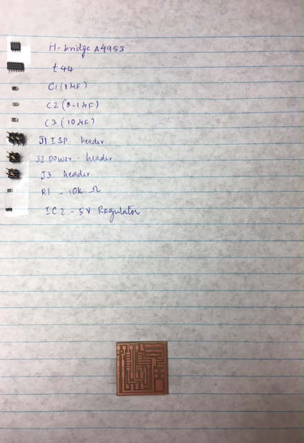
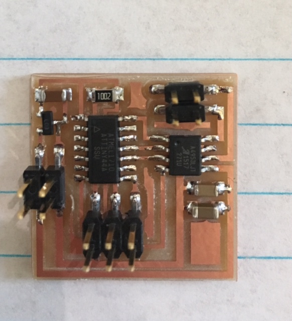
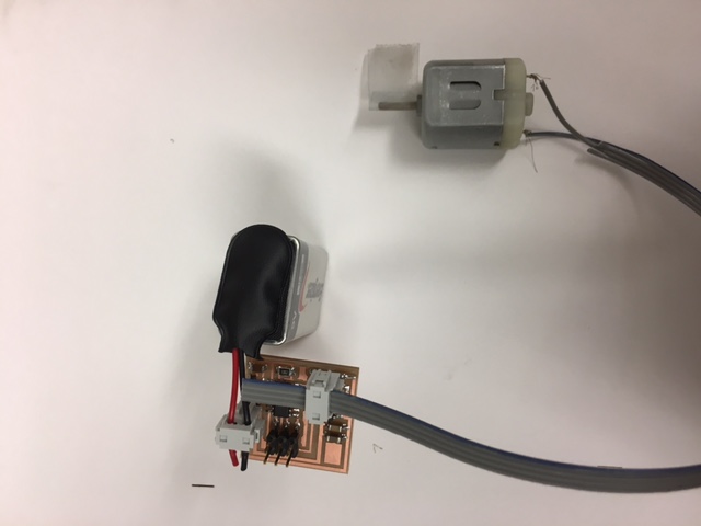
This week, we had to make a board that connect to an output device and program it. I decided to make a board to control DC motors with different voltage ratings, and rotational speeds, and learn to interface with the power supplies and program the board. After making and milling the board, I started with gathering all the components required. Notice that we need the H-bridge to run the DC motors. We hadn't used this component until now. It enables voltage to be applied in opposite directions. So, we can rotate in clockwise and anticlockwise directions. We could envision this being super important in robotics and other fields where we want objects to turn in different directions.

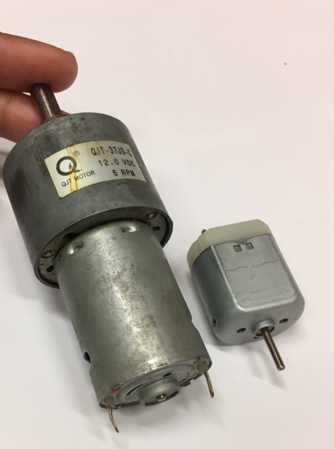
These are the two DC motors that I picked. One of them requires 12V DC, and the other requires 9V DC.
For the motor that required 9V, I used a 9V battery as power supply and connected it to the 2x2 header on the board that was providing the power to the motors.
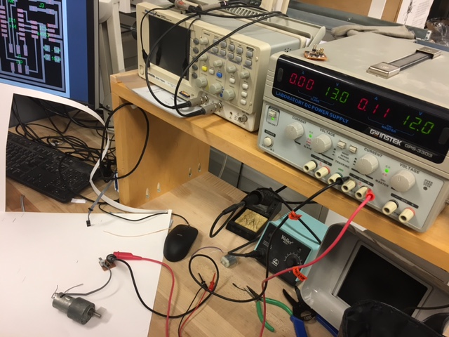
For the second motor, I used the power supply in the lab. I hooked up the pins using alligator clips, and then set the voltage on the power supply to 12V.
Here are some short videos of both the motors working !! We can see that the bigger motors rotate much more slowly but can support heavier loads, while the smaller motor rotates rapidly, but wouldnt likely be able to drive higher masses.
I also made an LCD display and heating element as output devices for my final project.. Check that out here!