For this week, I decided to learn about different communication protocols. Serial communication allows us to send one but at a time, sequentially, over a communication channel vs. parallel communication that sends several bits as a whole on a link with several parallel channels. There are different types of serial communication: Synchronous serial interface always pairs its data lines with a clock signal, so all devices on a synchronous serial bus share a common clock. Ex. SPI and I2C. Asynchronous communication means that data is transferred without support from an external clock signal. The asynchronous serial protocol has a number of built-in rules - mechanisms that help ensure robust and error-free data transfers. Data bits, Synchronization bits, Parity bits, and Baud rate.
Typically, I have used 9600 and 115200 as standard baud rates for communication with some of my boards. Serial bus consists of two wires - one for sending data, transmitter (TX) and one for receiving data, receiver (RX). Whereas I2C protocol is a multi master, multi slave serial bus that uses only two bidirectional open drain lines, Serial Data Line (SDA) and Serial Clock Line (SCL), pulled with resistors. Typical voltages used are +5 V or +3.3 V, although systems with other voltages are permitted. This week, I decided to learn more about I2C.
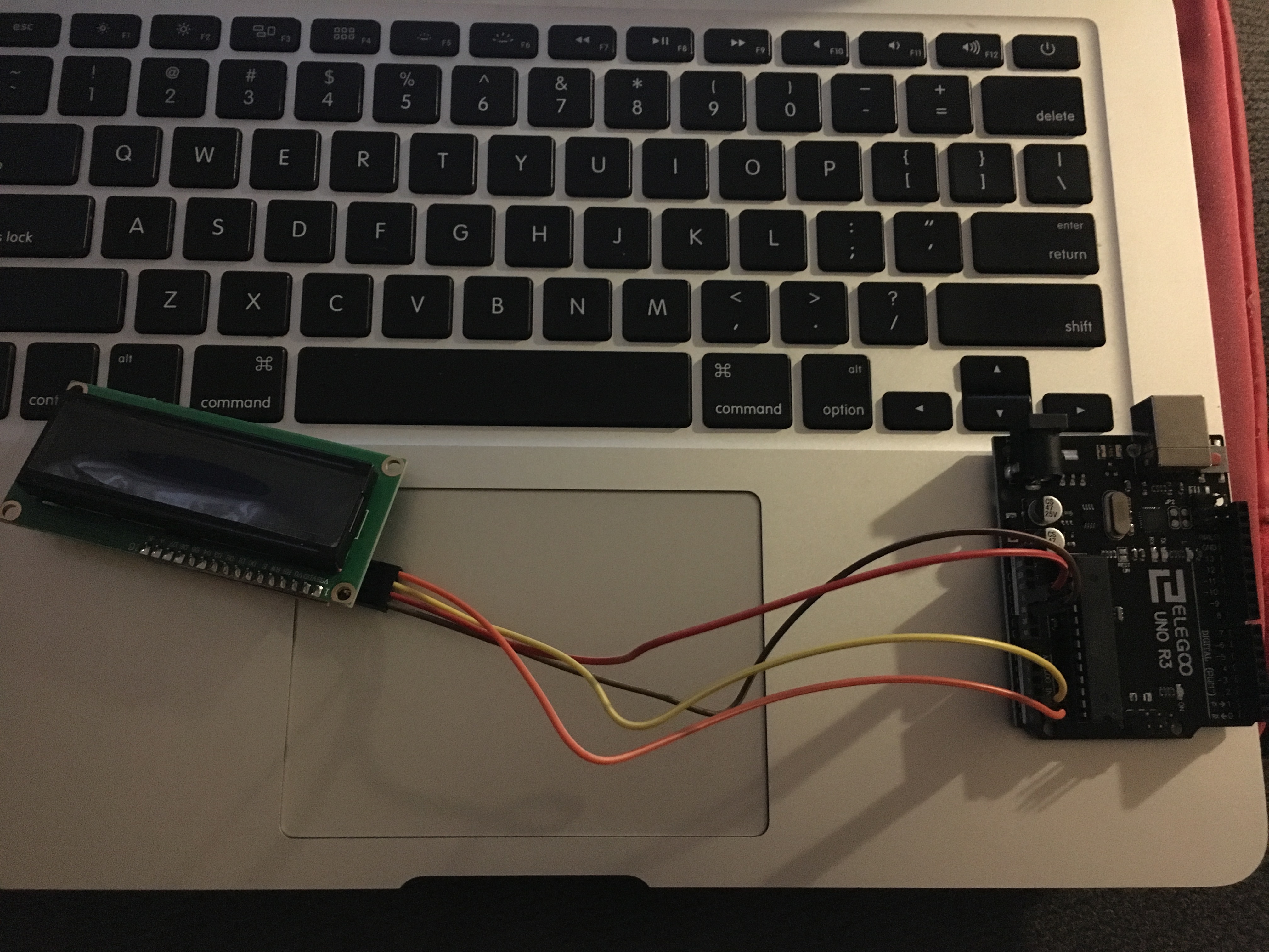
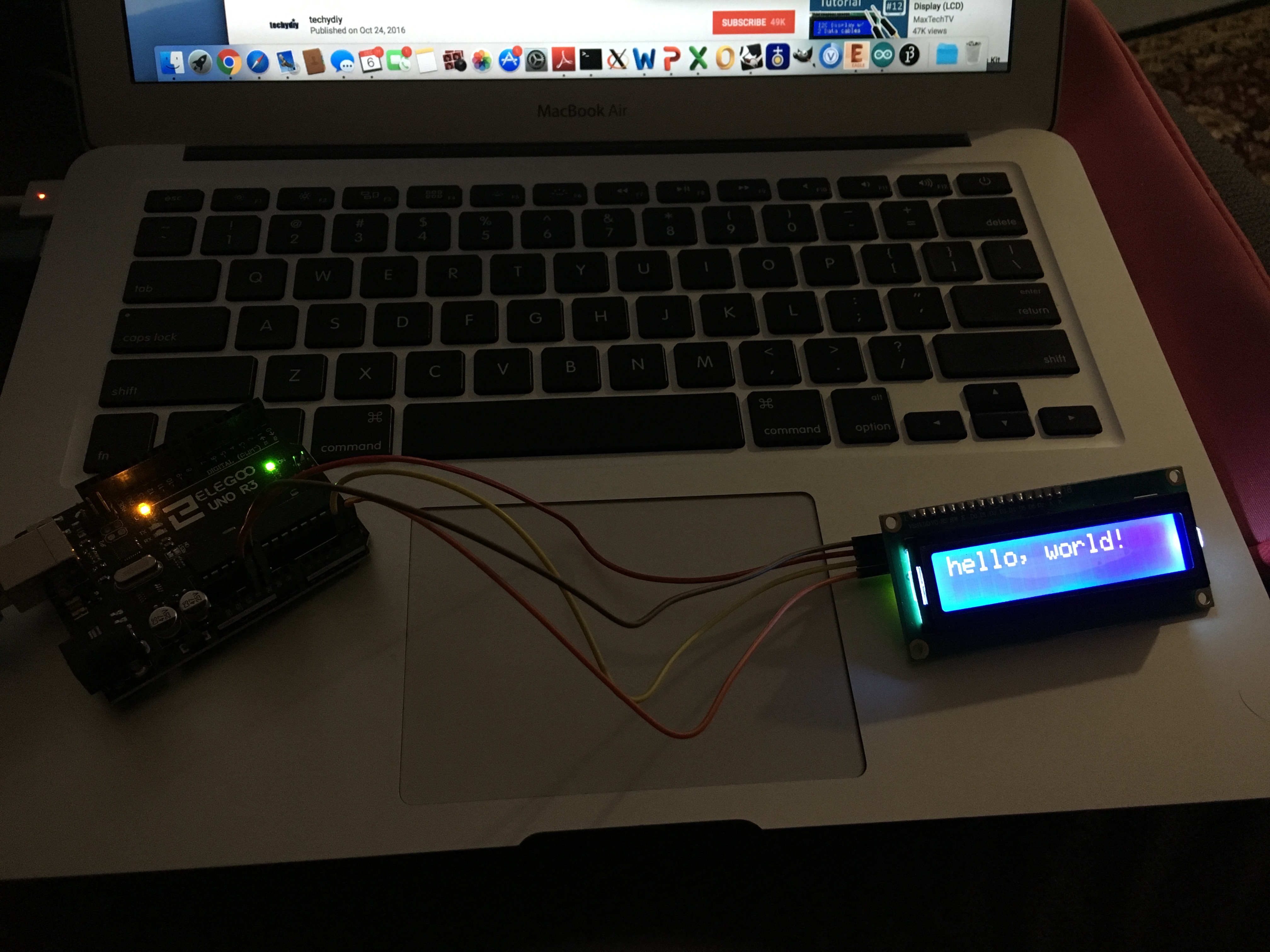
For my final project, I need an LCD display to display temperature from the temperature sensor. So, I started with getting the LCD display to work. The display came with an I2C bus. So, I hooked up the GND, VCC, SCL and SDA likes of the I2C bus with the Arduino Uno board.
The LCD display has the following ports: GND, VCC (5V), VO - Potentiometer to control contrast, RS - send characters, R/W - read/write - sending data or reading from LCD - have to be high when sending data, E - Enable, D0 to D7 - 8-bit parallel data port - values of characters - check ASCII, A, K - Anode and Cathode for LED backlight.
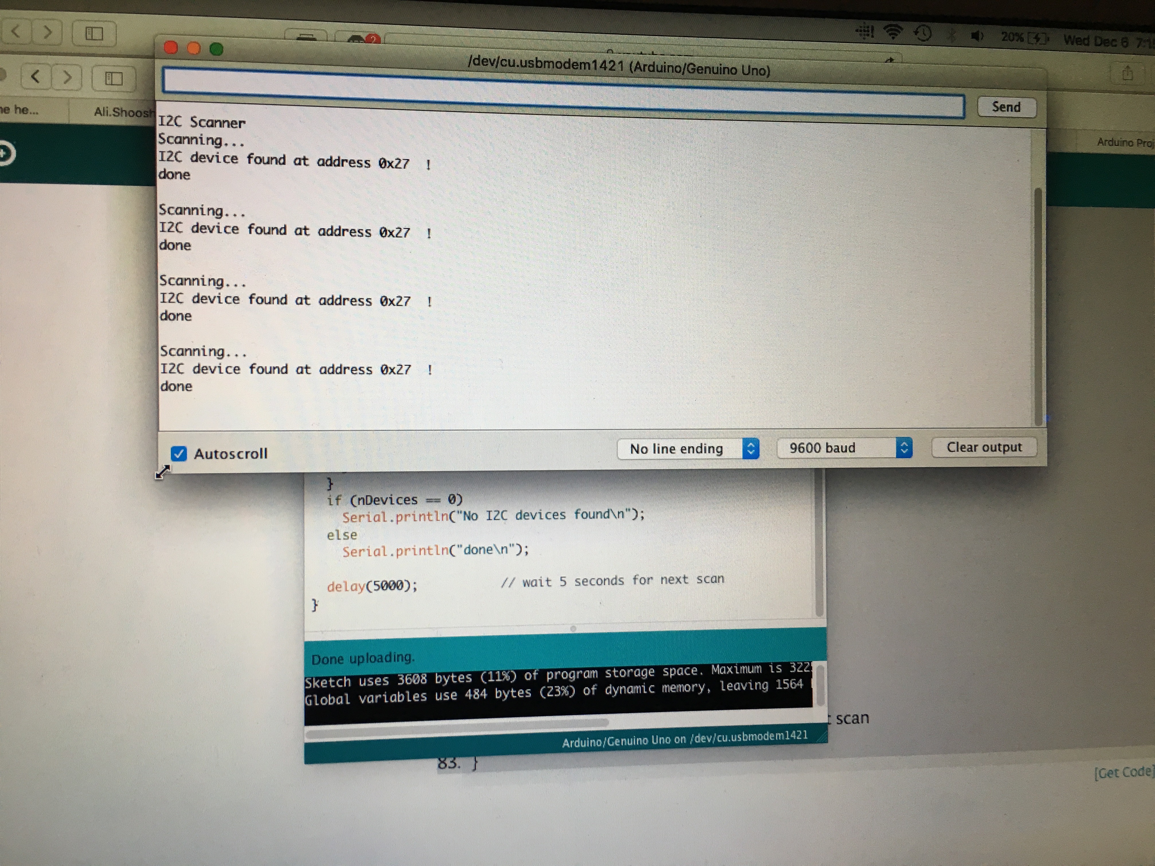
First, I had to download and add the library "LiquidCrystal_I2C". Then, I opened the serial monitor on Arduino IDE, and ran a quick scanner to detect the LCD display and display the port. The port that displayed was 0x27.
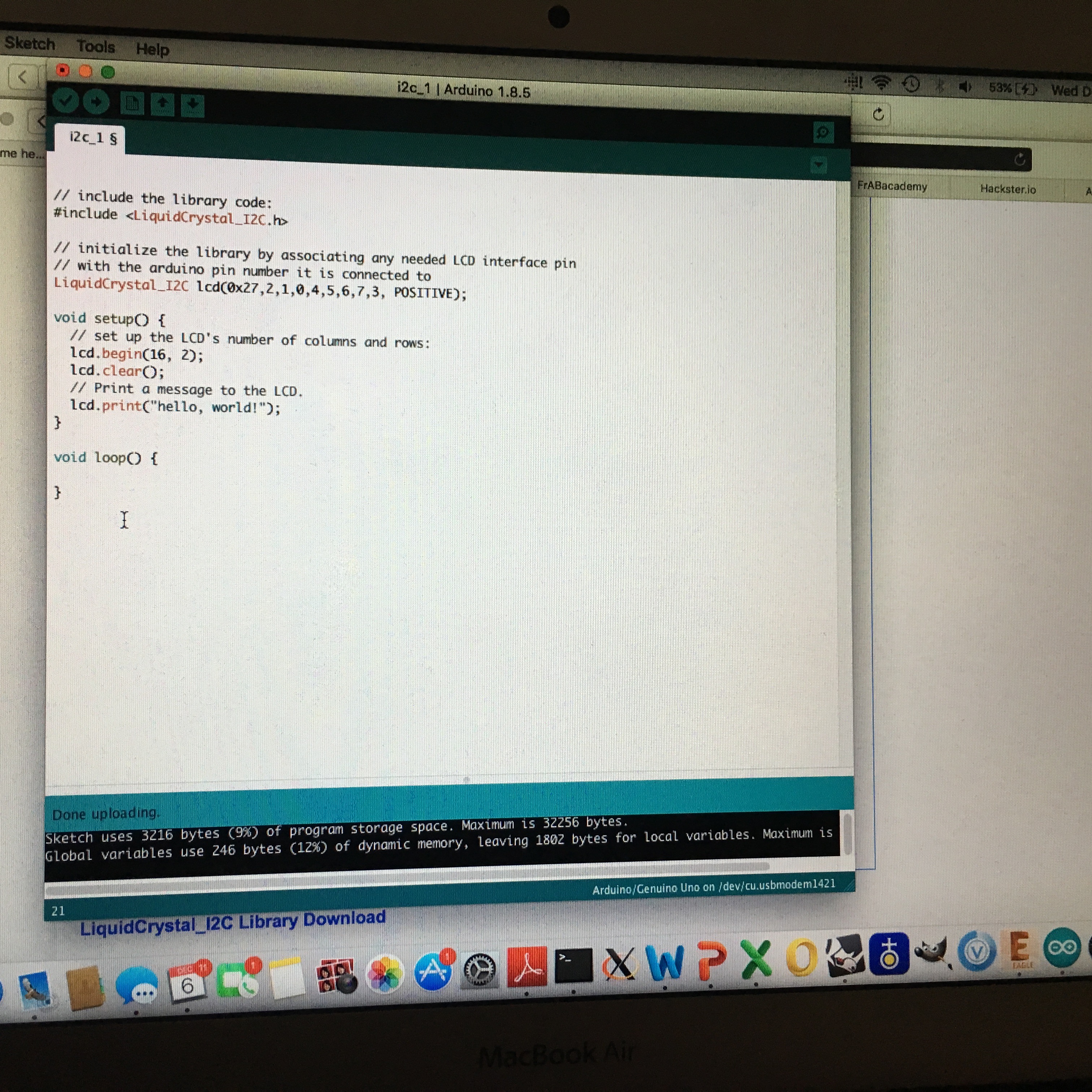
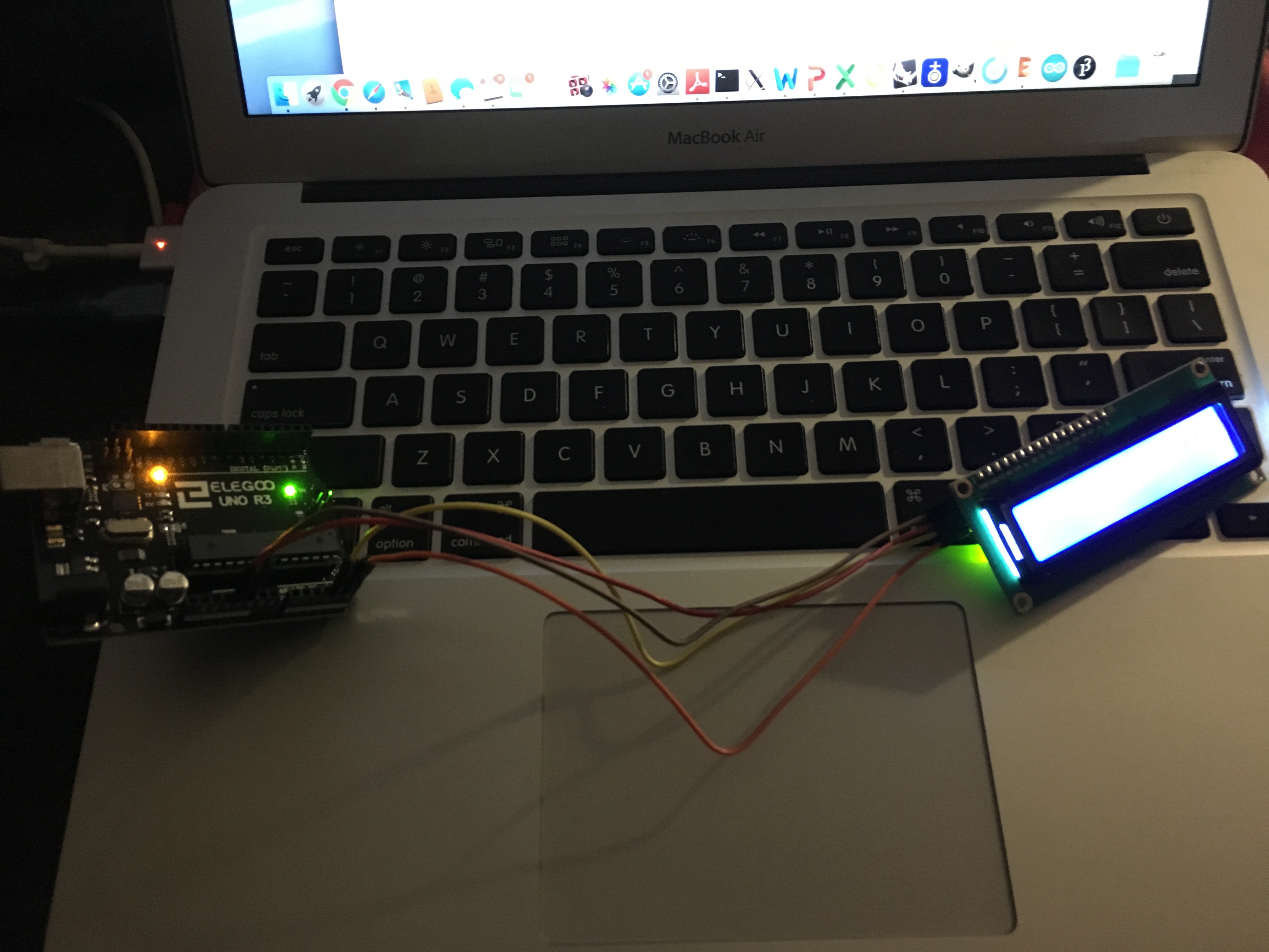
I uploaded the program, and there I saw "hello world" on the LCD display..
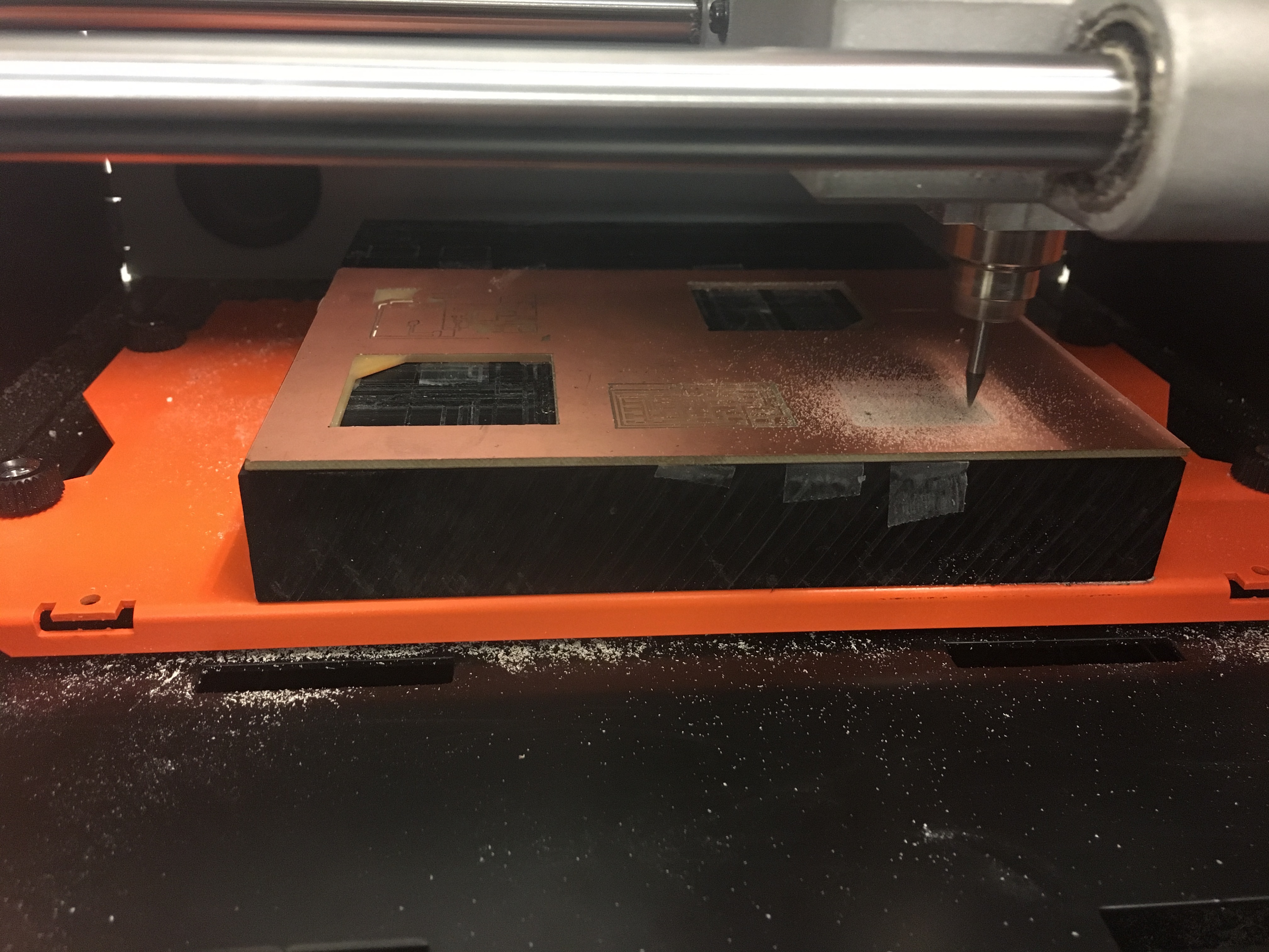
I then decided to make my own I2C boards (a master and slave board), and program it to light an LED, and then use the same I2C master board for the LCD display..
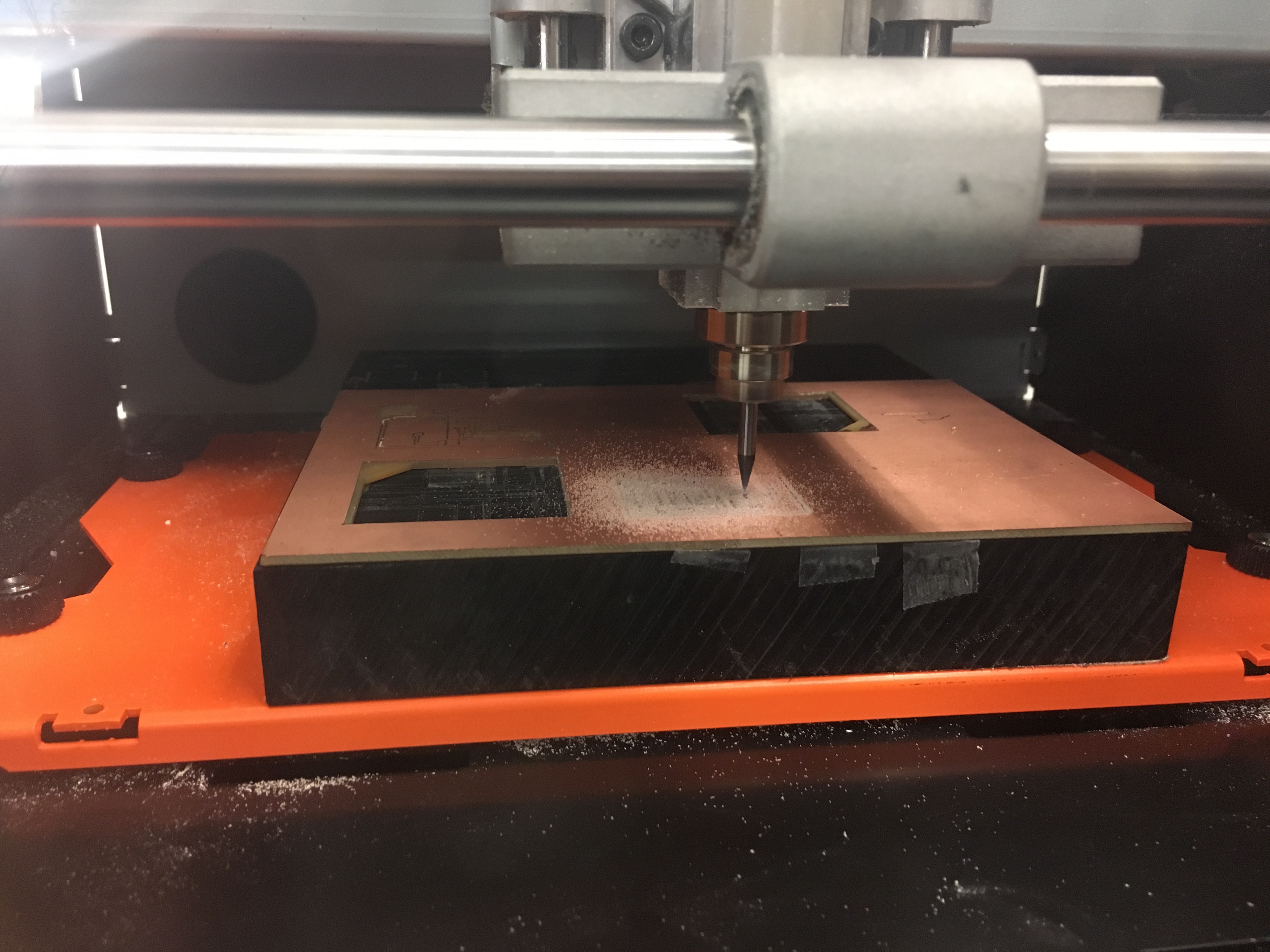
The production part went smoothly, and I was able to mill and solder the boards in under an hour, which was a vast improvement!
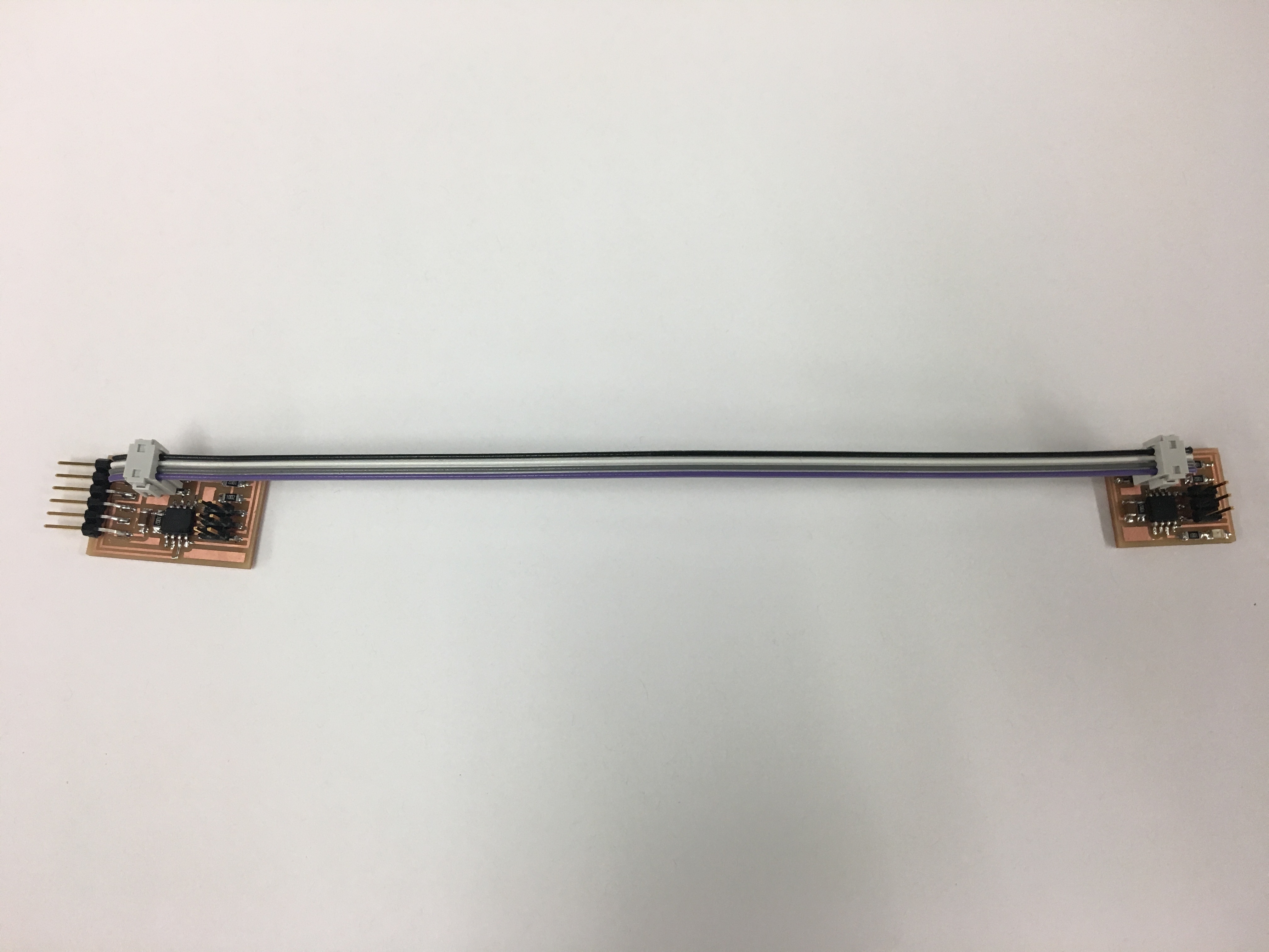
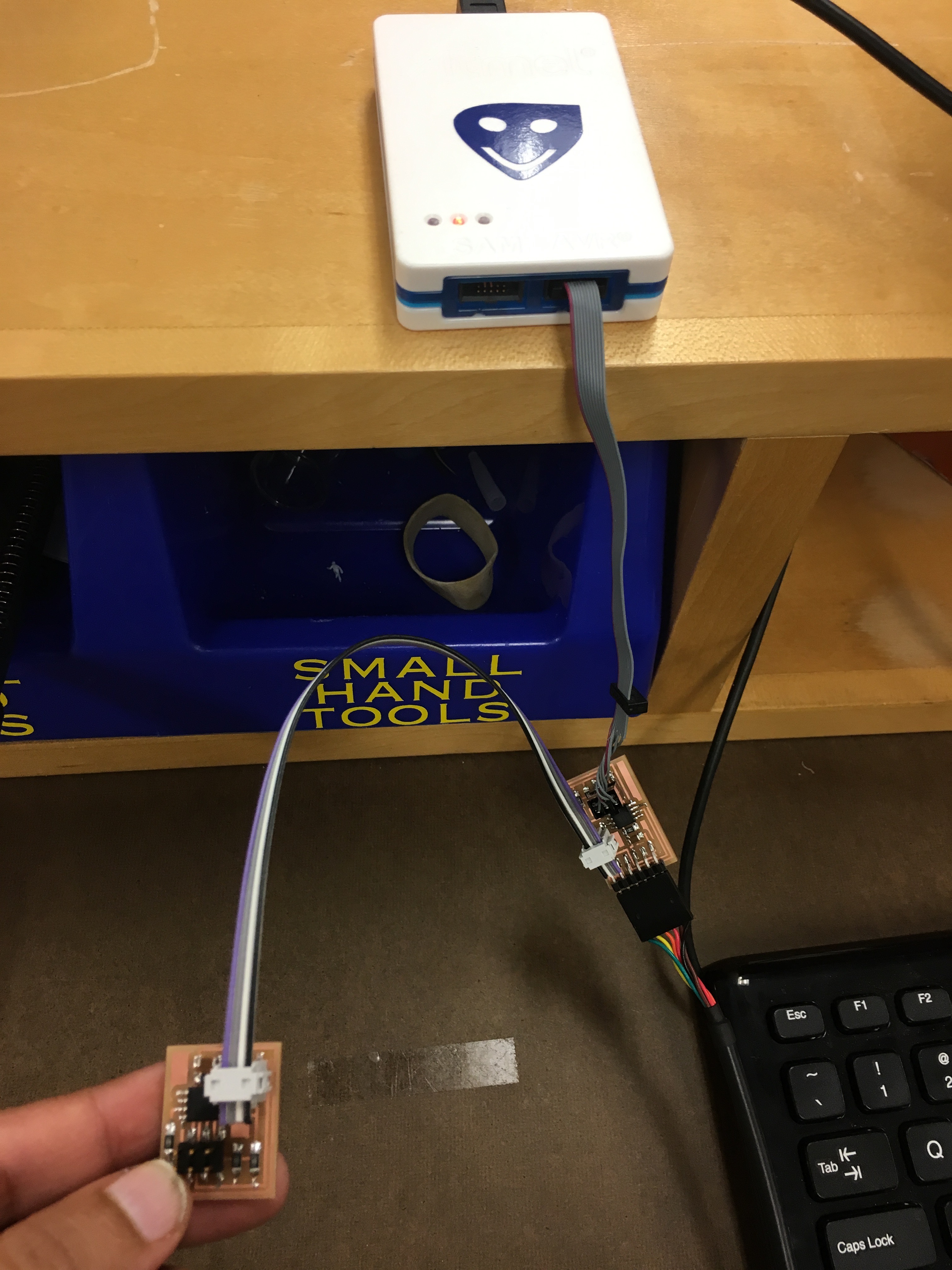
Here is a picture of the two boards - a master and a slave with wires connecting the 2x2 headers.
I then hooked up the master board to the AVRISP in an attempt to send/write information to the receiver.
I then connected the master board to the LCD display and used the FTDI cable to connect to the computer.
It was the end of the time for this week. I continued working with the LCD display and incorporated it into my final project. You can see the results here!