I’ll update this page as I make progress on my class project through the weekly assignments.
Index
- TL;DR
- Week 1: The Idea
- Week 4: The First 3D Print
- Week 5: The Hardware Design (Mechanical Design, Motors, Sensing, Electronics)
- Week 6: The Chassis Redesign
- Week 7: The Control
- Week 8: The Changes from Neil
- Week 9: The Later-Unused Arduino
- Week 13: The Circuitry (PCB, Chassis)
- Week 14: The Prototype Iteration (Robot v.1.1, Robot v.1.2, Robot v.1.3)
- Week 15: The Final Countdown (Production, Video, Remote Control, Collective Movement)
- Future Work
- Parts and Files (Robot Components, Remote Control Components, Code, Design Files)
TL;DR
This page is long. Here’s a quick summary of the end result.
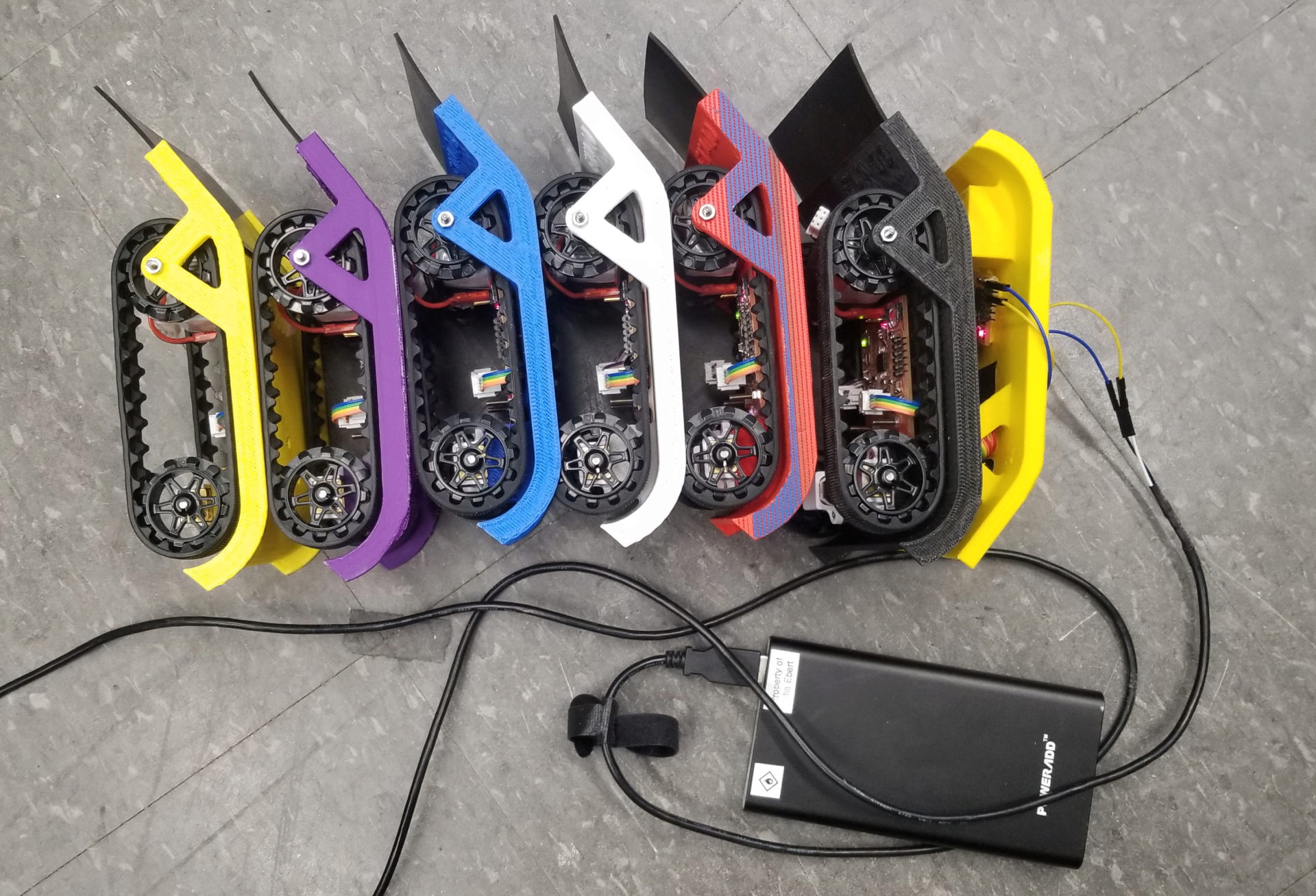
My goal was to make Overdrive: robots that drive over each other to move together as a group. This is what went into making each of my six robots:
I controlled the robots with an infrared remote, and each robot also has an infrared LED on the bottom of it. When a robot senses IR light (from the remote or another robot overhead), it stops moving until the light is gone. The robots move together, even over small obstacles.
Week 1: The Idea
For my final project, I am interested in building robots (hopefully more than one) capable of aggregate locomotion. This is based on the locomotion of sawfly larvae (genus Perreyia). I first saw this behavior in a video from Smarter Every Day on YouTube:
The larvae are moving on top of each other, using the layers below them like the moving walkway at an airport to speed up how fast they are moving. Counterintuitively, this leads to the group as a whole moving much faster than any individual could move on its own. In principle, if there are \( n \) layers each with the same number of larvae and each larva is moving with velocity \(v\), the velocity of the group as a whole is . With 3 layers, that 1.5 times as fast as they could move on their own!
This has some really cool implications for collective swarm robotics: it would allow a group of small, slow robots to move much more quickly between locations. For example, if (in some future world) you have a group of robots collectively constructing a skyscraper, they could move between sites on the tower a lot faster and get a lot more work done.
However, it looks like very little research has been done on this approach to aggregate locomotion, both in biological systems and in robotics. I want to build a simple robot that will be capable of this type of movement in two dimensions, including using detected forces between the individuals to stop and start the group’s movement.
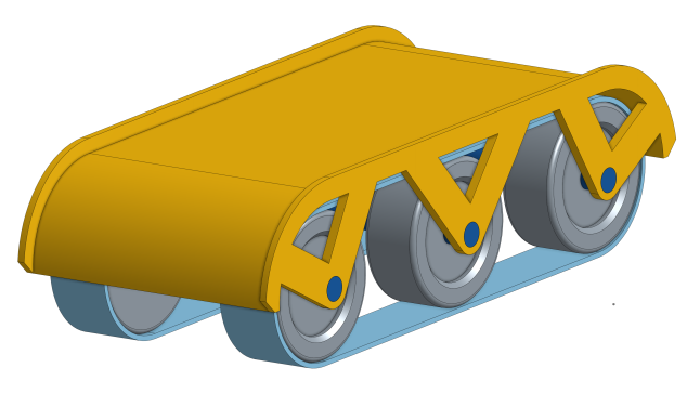
In the first week, I proposed a project to create a group of robots that could climb over each other to move faster than a single robot on its own. Knowing nothing about mechanical or electrical engineering, I knew from the start that there would be a lot of changes required to make this thing work - both to get a single robot moving as well as to get the collective behavior I’m looking for. This week I made a very simple, naive model of what I imagined the robots looking like, without having any idea of sizes or what parts I might end up using.
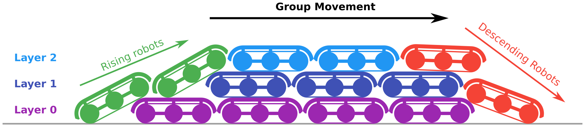
I also made a diagram of what the collective behavior entails (below). Robots on the bottom/lower layers will be slower (purple robots) and end of becoming “uncovered” at the back of the group, at which point they are unburdened by the robots on top of them and are able to start climbing of the back of the group (green robots). The robots on the top (light blue) use those below them as a moving walkway to reach the front and start descending (red). As they descend, they move slower and are eventually pulled under to the bottom layer.
Week 4: The First 3D Print
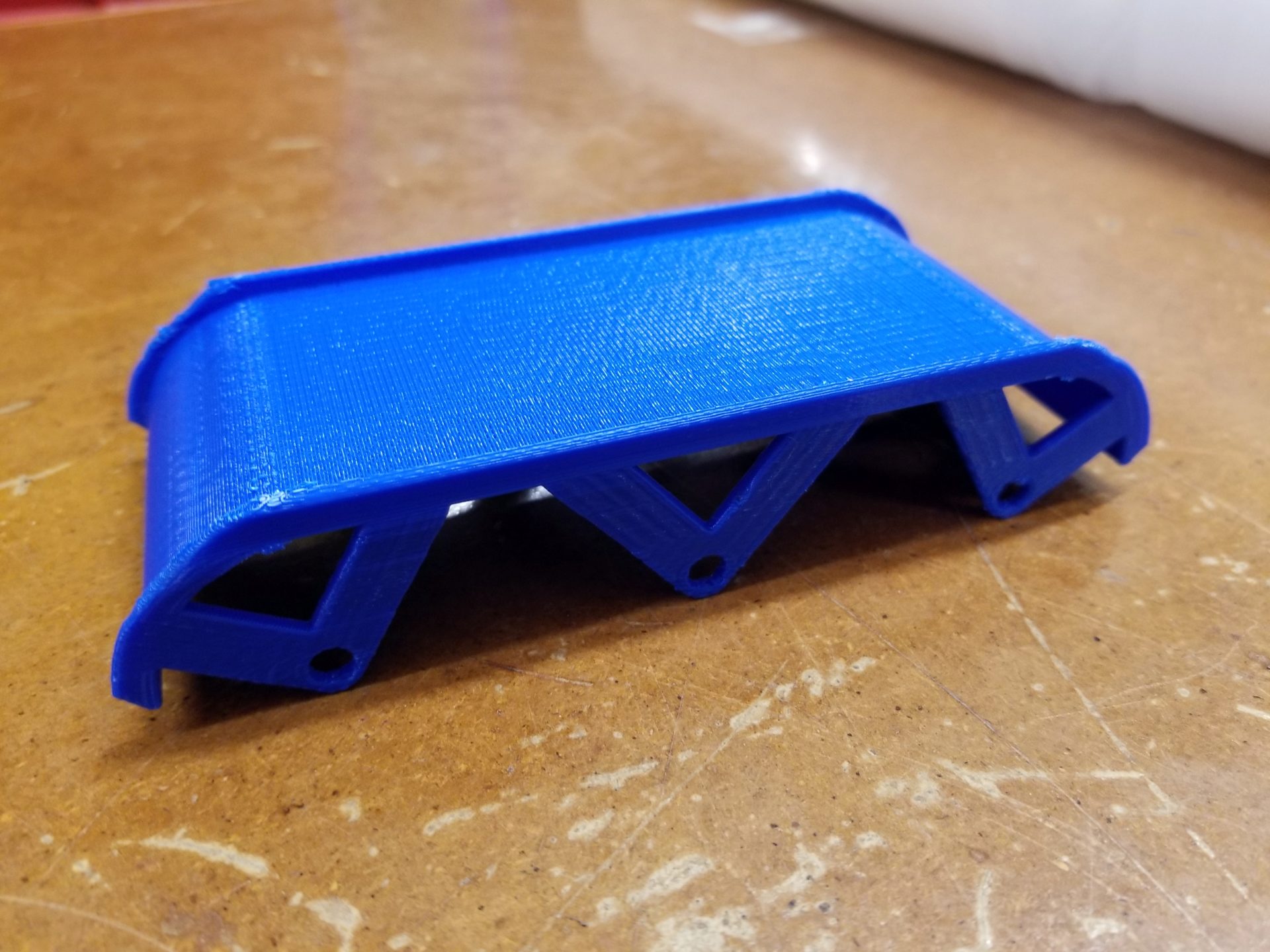
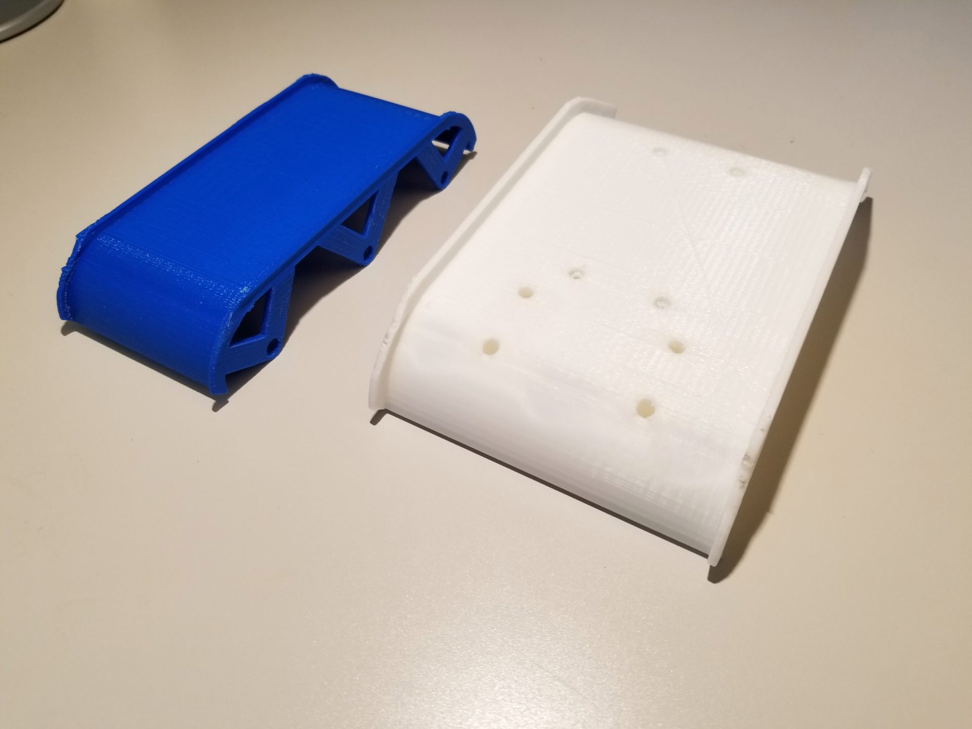
In our 3D printing week, I made the first prototype related to my project when I 3D printed my first cover design for the robot. (You can check out more on my Week 4 post.) From this initial print, there were a couple of things that immediately jumped out as changes I’d need to make:
- It’s too small. This would make an adorably-sized robot that will fit in the palm of my hand, but it will be too small to fit all of the electronic components, wheels, and motors underneath the cover. In particular, it will need to be a lot wider.
- I need to make things thicker. The axle supports and lip are very thin, and the lip is so short that it won’t do much to keep the robots from driving off the side of each other.
- If I change the angles of the struts, I can get rid of the need for support material inside of the struts.
- The ends are too steep. The robots need to be able to climb onto each other, and the quarter circle at each end means that when a robot tries to climb up the back, it’ll be impossible. Their covers will hit each other rather than the rear robot’s wheels or tread getting to the cover, and even if the wheels made contact, it would likely be too steep to climb up. The easiest solution is to make the robots asymmetric, with a more gentle ramp off the back to start climbing and a more blunt front end that will help robots get sucked into the bottom layer when the reach the front of the group.
In addition to these changes to the cover, I also started thinking about additional improvements to my initial design. In particular, I started questioning my plan to use tank-style treads. I initially selected treads because they would provide grippy contact with the surface at all times when climbing and prevent the robot from “bottoming out.” However, treads are difficult to adjust and calibrate the tension. Plus, the tension of the treads can quickly cause 3D printed tread guides to warp and become unusable, as people in my lab discovered on this robot.
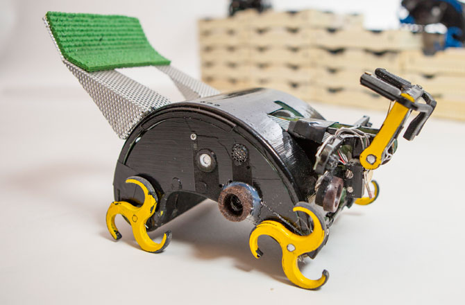
Is there a simpler alternative to treads? One option is “whegs” (a portmanteau of “wheels” and “legs”), as shown on the Termes robot to the left. The grabiness of whegs makes them particularly good for climbing things about the same size as them. However, since whegs are not circular, this causes the robot to move slightly up and down as the whegs turn. This might end up being a problem when the robots are stacked on top of each other. Another alternative is to just use some grippy rubber wheels. This is by far the simplest solution, and I could use existing, commercially available parts. Both wheels and whegs could face the problem of bottoming out as they climb, depending on the angle of the climb and the spacing of the wheels. If I don’t use treads, I’ll have to think more carefully about the length of the robot or keep a third set of wheels/whegs in the middle.
Another way to help the robots climb and move easily is to give them good grip on the backs of others - rubberizing the top of the robot covers. One way to do this would be a two-material printer to print the rubber as part of the cover. But since it’s a rectangular piece with curvature only in one direction, it would likely be easier to just cut out and glue on a piece of rubber. This could also end up helping create the ramp for robots behind to climb. With only a rigid solid cover, the longer, lower, and gentler the slope off the back, the smaller of a maximum angle the robot will be able to climb. If more of this ramp tail is made with flexible rubber, the longer, lower, and gentler the ramp can be while still allowing robots to climb at steeper angles.
Based on these ideas, I’m currently redesigning the next iteration. It will be larger, asymmetric to have a gentler slope in the back, and have greater clearance to allow for swapping out and testing wheels, whegs, and treads.
Week 5: The Hardware Design
Mechanical Design
I talked to some labmates about my robot plans and uncertainty about where to start looking for parts. A postdoc, Nic Carrey, suggested Pololu micro metal gearmotors, which it turns out a number of people in our lab use on their robots since they’re very small and affordable.
I enlisted the help of my friend Clark Teeple to help me figure out some of the mechanical engineering and design parts of my robot. Some of his recommendations:
- Go for tracks (instead of wheels or whegs). They’ll prevent bottoming out and avoid the need for a gearbox or drive belt. We specifically looked at these tracks from Pololu, which say in the description that the tracks are elastic enough to allow some wiggle room in terms of positioning.
- Add fillets to all the concave corners of my design to avoid stress points.
- To actually screw the motors to my 3D-printed cover, try countersinking the screws through the top surface of the cover. I may or may not have to end up solid-printing the blocks the motors sit on for stability here. Based on the bracket specs and a chart of hole sizes, I’m planning to use a 0.0960” free fit hole, planning for the possibility that FDM printing may have oozy material and make the hole a little smaller.
- Since I belong to a lab that’s part of the Wyss Institute, I apparently have access to all sorts of awesome 3D printers at 60 Oxford St., some of which can do multi-material printing, including rubbery materials. I could try using this to print a grippy top surface as part of my cover part.
Motors
Clark also helped me figure out what motors to try; that list of motors is really intimidating. We went through some back of the envelope calculations. First, we estimate how fast we’ll need the motor to turn. I started with the estimate of wanting a robot to go up to \(v=1 \text{ m/s}\). From the size of the tread guides, we also have \(r=17\text{ mm}\). We can calculate the angular velocity:
This is the speed you’d need assuming there’s no torque – that you have a weightless robot. The robot will be pretty light, but it’s still best to round up from there to figure out how fast of a motor to get. From the available options here, this makes the \(625 \text{ rpm}\) option look best. But how much force can this handle? The stall torque for all of the \(625 \text{ rpm}\) motors is \(15 \text{ oz-in}\) (do people actually use these units?), which more usefully is \(0.106 \text{ Nm}\). To figure out the force at the tread, we use our tread radius as the moment arm:
To give a sense of what that means, how heavy of a robot could the motor pull vertically? (If the robot were going up a wall while somehow magically stuck to the wall.:
But the robot won’t be going straight up. At this point, the ramp slope is \(30\deg\), which means only half as much force (a factor of \(\cos 30\)) is needed to counteract gravity, so the robot can be about \(1.27\text{ kg}\).
At this point, we remembered that the robot will actually have two motors, so you’d only need a motor half as powerful, right? But the biggest limitation here is likely not the slope – it’s the fact that robots will be trying to crawl forward with more robots on top of them and pushing them backwards. That means that all of this is just enough to give us an estimate of the motor power. I can start with this and adjust based on my experiments, because the motors should be pretty easy to swap out by unscrewing the bracket.
For the \(625\text{ RPM}\) motors, there are both \(6\text{ V}\) and \(12\text{ V}\) options. The \(6\text{ V}\) requires higher current and would be slightly less efficient. But a quick search of my lab’s Amazon history showed that people are generally using \(7.4\text{ V}\) batteries on their robots, so I’ll plan for \(6\text{ V}\) motors for now.
Finally, there is an option for a double shaft motor or not. The double shaft lets you attach an encoder to measure the velocity of the motor (and estimate position). For future research and analysis, I’d really like to know how fast the robots are moving, so I’ll plan for using encoders. Which finally narrows it down to the 50:1 Micro Metal Gearmotor HP 6V with Extended Motor Shaft.
I’ll probably come back to this more in the week when we look at output and motors.
Sensing
My robots need to know something of what’s going on around them. Specifically, I want a robot to be able to know when (1) there is a robot on top of it and (2) the robot on top is walking over it. I need some sort of force sensing, but all force is relative to something. I need to be able to detect force between that upper robot and the current robot. I could add some sort of flexure in the top of the cover and put a force sensor between that and the solid part of the body. Alternatively, I could put something like these force-sensitive resistors between the rubber top coating and the body. However, I don’t know how sensitive these sensors are, and the description even says that they can be very inaccurate. This sensor film kit seems interesting. I’ll also probably play around with force sensors the week we cover inputs.
Those would allow me to detect the downward force of a robot, but how do I sense a robot driving on top? My first thought was detecting a horizontal (forward/back) force. But I’m having a hard time figuring out how to detect this kind of shear force. Another option is just more force sensors, along the length of the body. Then I’d be able to detect as the weight of a robot moved from back to front over the robot below. I’ve got two concerns here. First, how many sensors would I need for this? Would just two (front and back) be enough? Second, how well would this work as you get more robots piling up? For example, when there are two robots on top of a single robot, or when there are multiple layers of robots.
I’m now feeling a lot more confident about the mechanical design and movement of the robot, but the sensing is looking like more of a challenge than I’d initially given it credit.
Electronics
Here are the electronics components that at this point I think I’ll need:
- Raspberry Pi Zero
- 7.4 V battery
- 6 V voltage regulator to power motors (a linear regulator will likely be fine, since the loss voltage drop is relatively small)
- 5 V voltage regulator for Raspberry Pi Zero
- Motor driver (h-bridge): TB6612FNG Dual Motor Driver Carrier. This one can drive two motors, and it specifically says that it will work with the motors I’m planning to use. Depending on how many other small parts I end up with, I could end up making my own PCB that incorporates the voltage regulators, h-bridge, maybe something for force sensing, and whatever other electronics don’t directly connect to the Pi.
- Motor encoders (2): Magnetic Encoder Pair Kit for Micro Metal Gearmotors, 12 CPR, 2.7-18V (HPCB compatible)
Week 6: The Chassis Redesign
At the beginning of the week, I printed the update chassis part. It’s now significantly larger than the first version, once I’ve left space for the motors, Pi Zero, and wheel tracks.
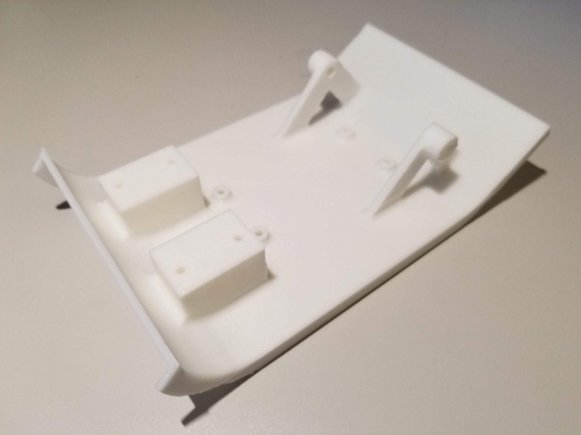
There’s now actually stuff on the bottom as well. In the front are blocks for the motors to sit on, with screws holes through from the top for the motor brackets. In the back are mounts for the rear track wheels. They turn freely and are driven by the motors in the front, which makes things easier here. I did my best with the diagrams from Pololu, but I still feel like the front and back wheels won’t line up. If not, though, then I can just make an adjustment and reprint!
In the middle there are offsets and screw holes for a Raspberry Pi Zero. Since I’ve got a couple of these laying around, I could actually verify that these work! The holes are the right size and line up perfectly. It’s really simple, but it’s super satisfying when something you make actually works with an existing part.
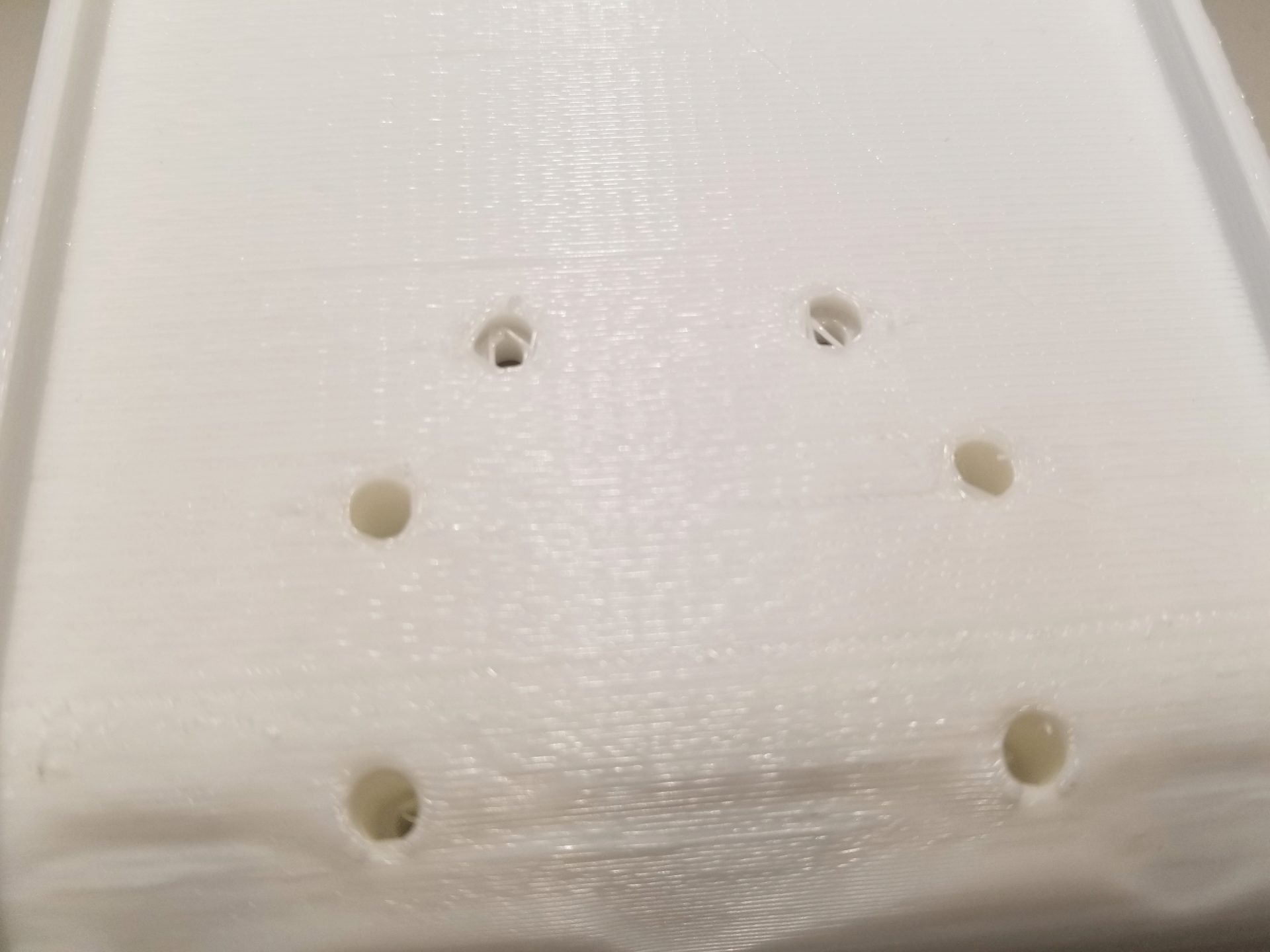
Lastly, about those screw holes. The screw holes for the motor bracket and Pi Zero are countersunk from the top of the chassis. But I printed my part upside down again to reduce support material, which means I ended up with support material inside of the holes. You can see some strands here. I don’t have the right screws on hand to test that they freely fit through. If not, I could drill through for this prototype and print larger holes on the next version.
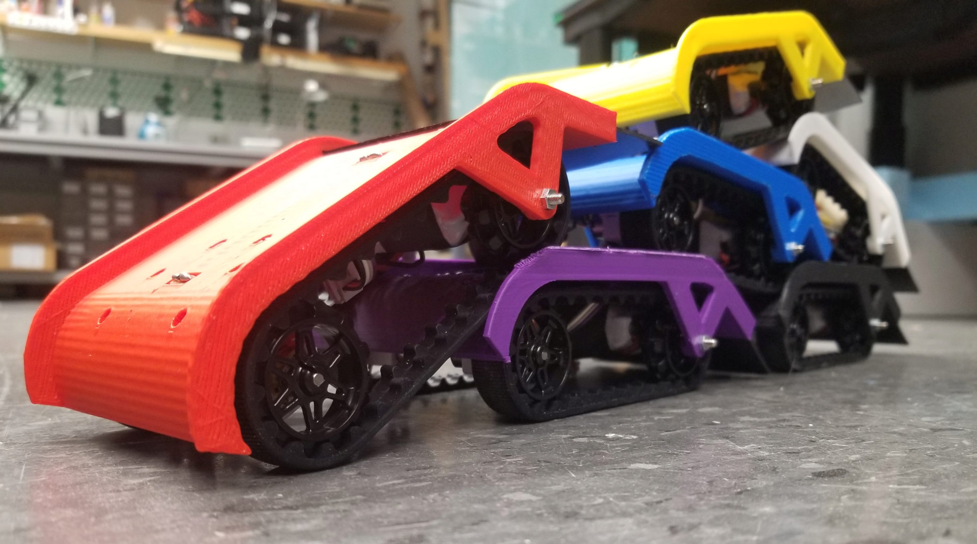
Also, totally unrelated to anything important, but when I print the final versions for my project, I want them all to be different colors. (If I can keep doing it on the 3Dwox, there are a lot of colors.) It is kind of practical, since it will help me easily distinguish the robots once I have more than one of them.
Week 7: The Control
Sensing and Control
This week I had some great progress on the design thanks to Jordan Kennedy’s husband Skyler Rydberg coming on our lab retreat and being willing to spend part of the evening talking engineering. I brought up my issue of how to detect velocity of a robot moving over the top of another robot. It’s easy to detect acceleration of a robot, but my challenge is distinguishing [zero acceleration and zero velocity] from [zero acceleration and non-zero velocity].
I was hung up on finding some way to use force sensors for this problem, but from Skyler and Nic Carey, I got a better idea: light! In this case, each robot has a light on the bottom of it, pointing downwards. Each robot also has a light sensor on the top of it. When a robot moves over the top of another, the bottom robot will detect a change in light intensity as the upper robot moves. With a single light sensor, the lower robot could detect whether or not the upper robot is moving; with two sensors, the lower robot could estimate the velocity of the upper robot by comparing the timing of light intensity peaks.
Using light sensors can also help solve another problem I’ve had in the back of my mind: How does the group decide when to start and stop? My preliminary idea was that robots on top will stop (like is seen in the larvae video), and when the robots below detect no movement above them, they will also stop moving. There are two problems with this:
- What triggers the robot(s) on top to stop moving? (And correlated, how do you deal with the fact that there are multiple robots on the top that all have to stop?)
- Once stopped, how do you trigger the robots to start moving again?
The light sensing can be used as a control signal to determine this behavior. For example, I could use red light as a control signal to tell the robots to stop. If a robot is on top (i.e., no downward force on it and a light sensor clear to the world), shining a red light will signal it to stop moving. This stop will then propagate down through the layers. Conversely, removing this red light (or shining a different color light) will signal the top layer robots to start moving, which will again propagate down to start the entire group moving.
After discussing with Melvin, we refined this approach. First, the plan is to use infrared light instead of visible light, which means much less interference from background light. Second, we’ll put two wide angle infrared photodiodes on the top of the chassis. With overlapping visibility cones, we can use parallax to determine the position of the robot on top (and therefore its velocity). We can also use a pattern of infrared light (e.g., flashing) as an external signal to the robots on top without creating problems like visible strobe effects. (Bonus: this also means we have to build a controller.) This ends up being similar to the way that the Kilobots are controlled.
At this point, it’s also becoming more clear what I’ll need in terms of additional electronics. I’ll likely make a PCB to incorporate all of my “accessory” electronics, like the h-bridges for the motors, op amps for the photodiodes, and the infrared LED. Mounting things on the limited underbelly of this robot might also prove tricky, so ideally I’d like to be able to mount it directly below the Raspberry Pi using standoffs and the same mounting holes. (Conveniently, this would also center the LED on the bottom of the robot.)
Simulation
For this class, I’m planning to build and program the physical robots. However, I’ll likely be very limited in the number of robots I’ll be able to build, and it will be hard to change them once they’re built. For another class, though, I’ve gotten permission to model and simulate this system as a project. In that case, I’ll do 2D simulations of larger groups of robots (likely with Pymunk) and can test different parameters of the system, such as weight of the robots, between-robot friction, maximum allowed torque, and shape of the chassis. This should help bootstrap parameter tuning that would be much slower on the physical robots. If time permits, I may also play around with genetic algorithms for design and control of the robot.
Week 8: The Changes from Neil
This week I got called on to talk about my progress, and now I have things I need to change. Mainly:
- Apparently we have to use a microcontroller in the project, which I’m pretty sure was never said before. But there go my Raspberry Pi plans.
- Neil suggested that I reinvent the wheel. Specifically, I could mold and cast my own treads instead of buying them. Yeah, I guess I could, but the time to design and make them, plus what I can guarantee would be a ton of debugging on the sizing and design makes me think this really isn’t worth it.
- I could make my own motor encoders instead of buying them.
- Instead of using the $17 Pololu motors, I could use the much cheaper ones that are in the lab.
On that last one, Brian later suggested that I just use the Pololu motors anyway. After seeing the motors in the lab, which are really bulky energy hogs, I’m liking this idea better. Based on my idea of using infrared to control the robots, Brian also suggested that I might be able to control the robots with a regular TV remote control. That would be pretty cool.
Neil cautioned that this type of project often runs into the problem that people don’t end up making more than two or so. I guess if you have to reinvent the wheel, stuff like that takes a long time. Based on this, though, there are some simplifications I can make to my project. I think I’ll ditch the motor encoders altogether, since I don’t have particular plans for them right now.
Week 9: The Later-Unused Arduino
Simplification? Who needs that! I’ve decided I want to use Arduino for this. Why? Because I can. Also, despite the fact that Neil decries the overhead of the Arduino libraries, it does simplify things a lot, especially stuff like timers. As I end up doing more complicated stuff programming-wise, making the board a more complicated Arduino-compatible PCB will probably end up simplifying my life.
So now I just have to figure out how to make a Fabduino-style board. The big things here are:
- Figuring out what the essentials are that I need on the board for the Arduino functionality. (There seem to be multiple Fabduino tutorials out there, but they don’t quite agree or don’t have all the information. Maybe I’ll start with this from 2011 or from 2015 or 2016.)
- Adding all my stuff to the Fabduino-style design. I could either leave these as break-out pins so I can modularly add functionality (e.g., motors, LEDs, photodiodes) on separate PCBs. This would mean I don’t have to remake the board when I add stuff, but it’s not as compact as the alternative of including as much as possible on this single board. And for my current robot design, space is at a premium.
- Program the bootloader onto the board. Apparently the FabISP doesn’t work well for this (according to Yuval), but it’s something I should only have to do once for the board. Currently I’m looking at this tutorial from someone’s page last year.)
- Program my board with the Arduino IDE.
Week 13: The Circuitry
PCB
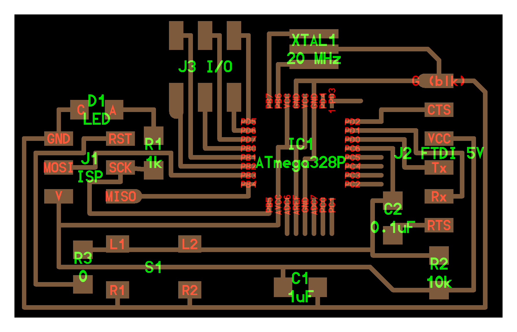
I made a lot of useful progress on my robot this week. In my post for this week, I talk more about the stupid PCB designing and mistakes that I made. The big progress here was integrating everything onto a single board. This was also my first venture into using the ATmega328P.
I started my design with the Hello World 328p board design, then started adding components for the additional functionality I’ll need in my final project: separate input power with a voltage regulator, 2 IR LEDs, 2 IR phototransistors on mini breakout boards, and motor controllers. Apart from my new method of motor control, the added parts all came from things I had done in previous weeks. Neil suggested making our board design modular to make it easier to change things, but I opted not to do that. This is partly because I’m really space-limited by the area on the underside of my robots, and partly because I’ll need to make a bunch of these for multiple robots, which I think would make multiple boards per robot more challenging.
In a change from output week, I’m now using MOSFETs to control my motors instead of h-bridges. First, I can do this because I only need my motors to run in one direction, so I don’t need the h-bridge’s ability to reverse the current direction. But the main reason for switching away from h-bridges was that (at least for the ones in our inventory) they required a 2-3 V higher input voltage than reference voltage. The problem was that I was running a 5 V microcontroller and powering my motors off of a 5 V USB power supply.
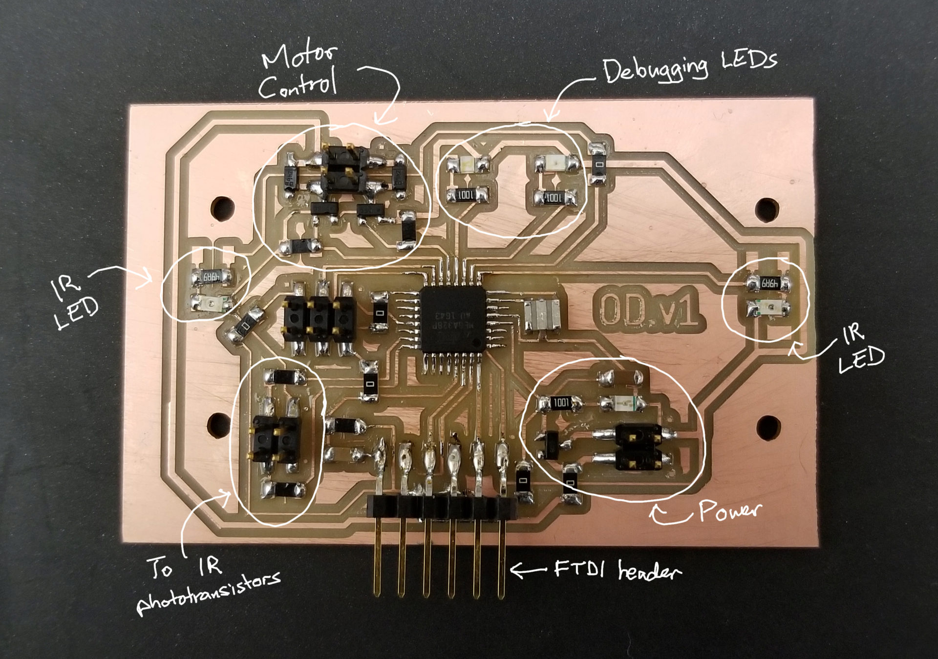
I spent a lot of time laying out the board. I suddenly have a lot more pins and space constraints. I measured out the maximum board size I could fit on the underside of my robot and set that up as the dimensions of my board in Eagle. I then added circles for the screws that I’d already designed into my chassis CAD model. I ended up needing only 6 0-Ohm resistors to get everything laid out. I have no idea how far from optimal that is, but it got the job done.
When I first connected my board to my USB power, my power LED didn’t turn on. Crap – where did I screw up? I connected through the FTDI header for power, and the LED lit up veeeeery dimly. That’s when I realized that I’d misread the Hello World board design I’d started with and added a 10k resistor between power and ground. But it didn’t explain why my USB power wasn’t working. My first suspect was the voltage regulating circuit, but it turned out that my board wasn’t the problem. For some reason, my hacky USB to 2-pin header from output device week had stopped working. So I sacrificed another USB cable to power my plans to take over the world.
Chassis
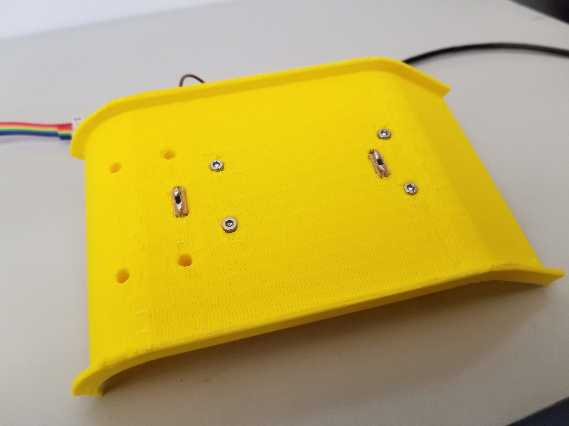
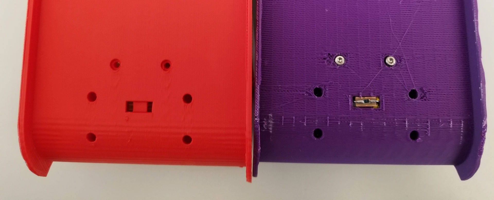
I also printed an updated chassis (v.1.1) – this time in bright yellow! I fixed the spacing between the wheels (I’d previously mistakenly made it 80 mm instead of 85 mm) and added holes to put the phototransistors on the top.
I was super pleased that the mini boards I created for the transistor were the perfect size for my boards. I was less pleased that I hadn’t accounted for the size of the header pins I was trying to fit through the chassis. I’ve updated my design for the next print, but for this version it was easy enough to hack it with a power drill.
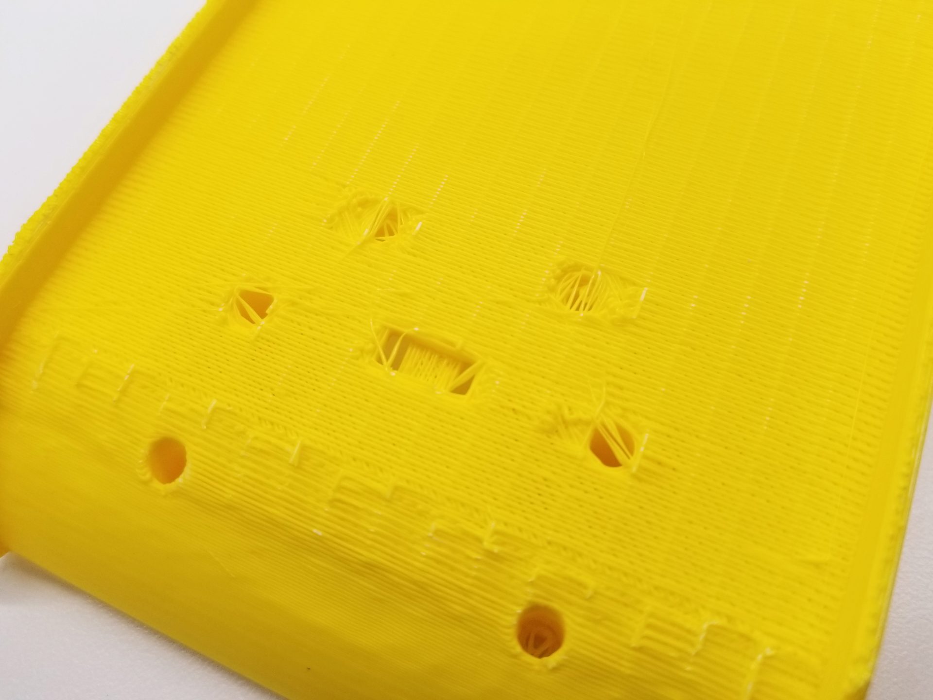
There were a couple of other minor annoyances I ran into on this print. One was the extra filament strung across the various holes by the FDM printer. An exacto knife fixed this for the phototransistor openings, and for the screwholes I smashed my way through with a tiny screwdriver. I don’t think there’s an easy way around this without using a different printer, but it’s pretty minor. The other issue was that I didn’t check availability of screw sizes before designing the PCB mount. I designed it with holes for M2.5 screws, from back when I was going to use a Raspberry Pi Zero and never returned to that decision. It turns out that our section lab didn’t have M2.5 screws, nor did my lab (in the completely disorganized file cabinet drawer just labeled “hardware”). So I had ended up getting some from a friend in a mechanical engineering robotics lab. Edit: I found huge bag of M2.5 screws in my lab while looking for something else completely. One less thing to change about my design.
I attached my PCB, and to my relief the holes actually lined up and I’d measured the maximum board size correctly. I’m still constantly surprised when things I make actually work together, especially on the first try. I was able to compile and run the example blink code for the 328P (code, Makefile with one of my debug LEDs, but that’s about as far as I could get without the rest of my robot parts.
Week 14: The Prototype Iteration
Robot v.1.1
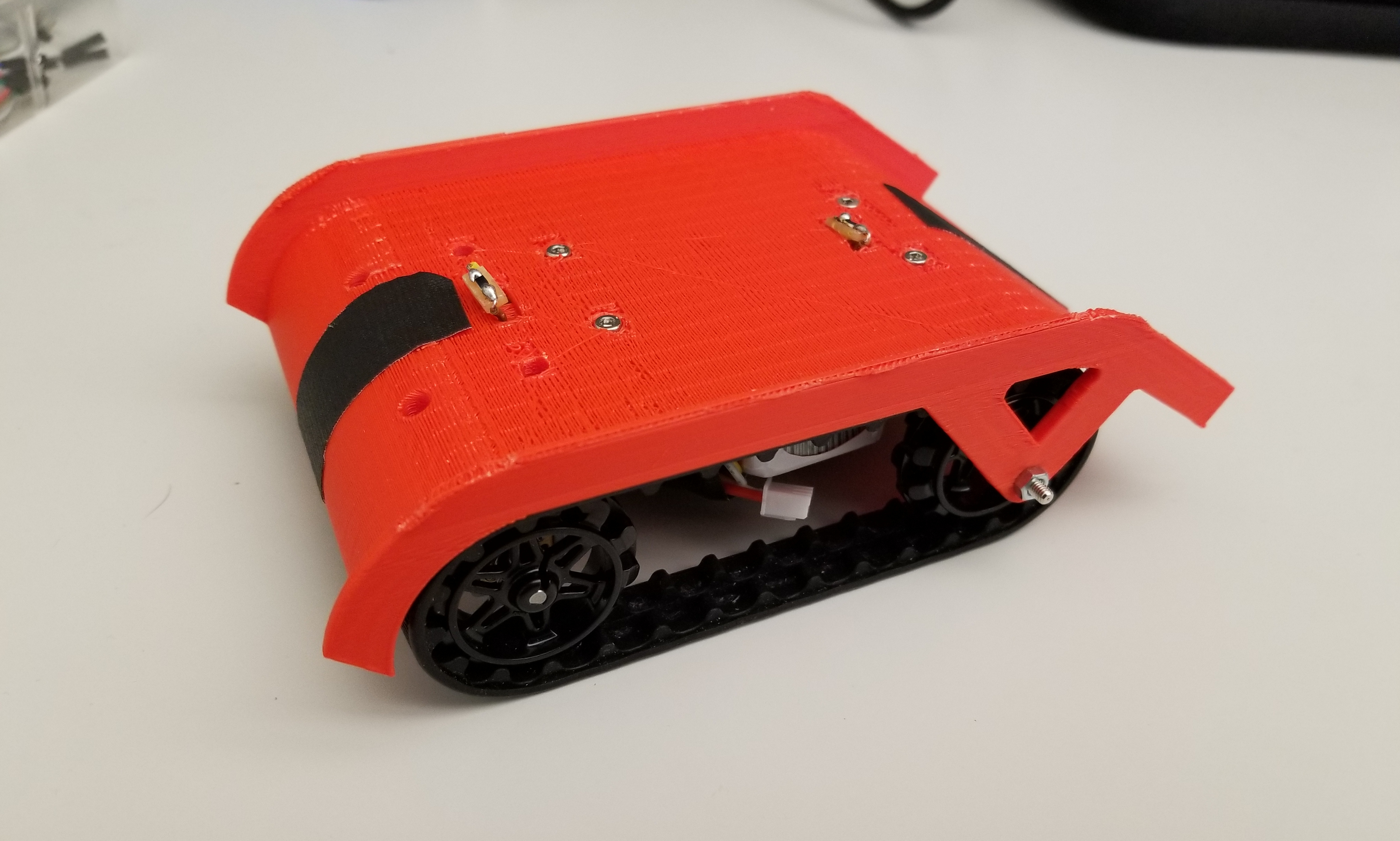
I have parts! My first pair of motors, brackets, wheels arrived from Pololu (after spending some time wandering through the mailroom, given how long they took to get to me after being delivered). I put it together and it looks like a real robot. Sort of like Pinochio in reverse?
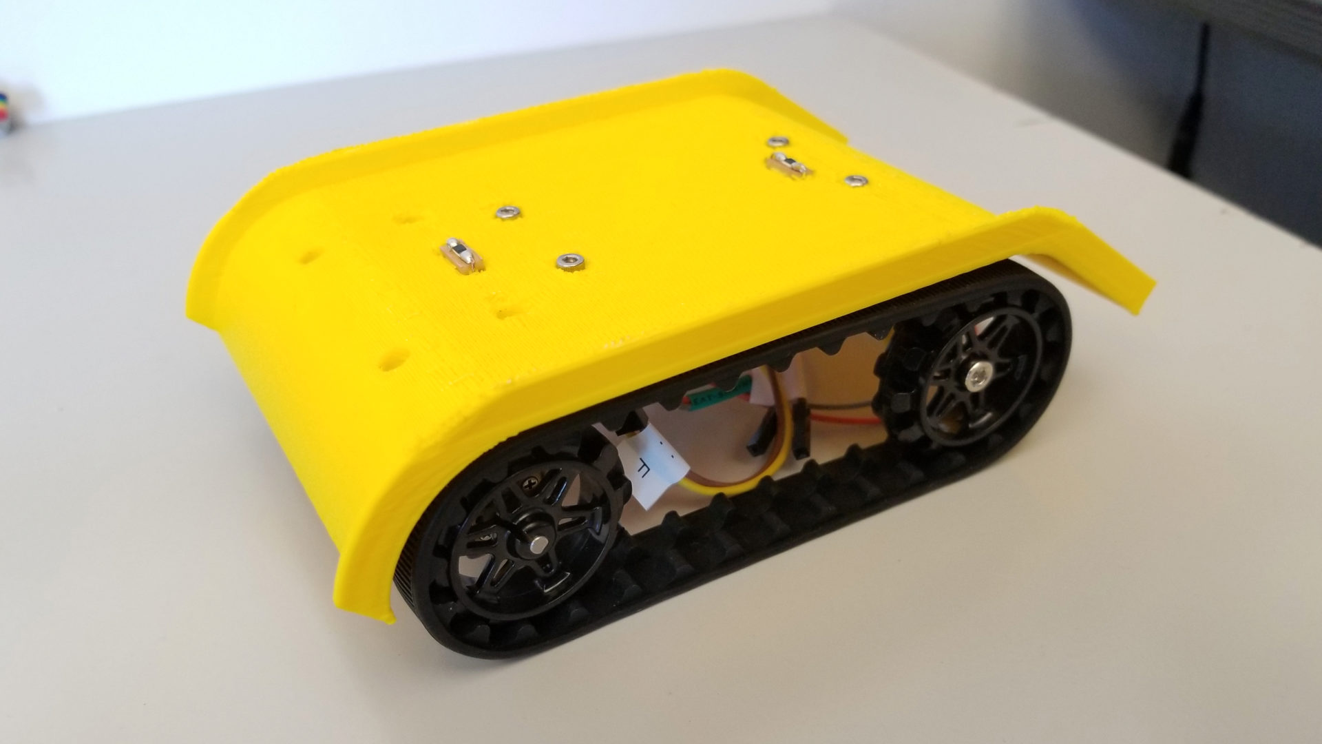
It was pretty fun to unpack all the parts and have them fit onto my chassis like it was a kit. I was really pleased that my counterbore holes for mounting the motor brackets were exactly the right depth. I also managed to lose one of the tiny nuts as I attempted to assemble things in a bad order at first. But my design still had some issues. The main one was that I’d messed up the calculations of where the motor mount and rear strut needed to go. This means both wheels are too close to the edge. The rear wheel is even further out than the front wheel, making the robot sort of bow-legged. I’ve updated that in my next design, hopefully correcting the issue. This is tricky, though, since it’s trying to pull the right lengths and distances from the datasheets for the motors, brackets, and tracks. Since I don’t have models for these, it’s tricky to verify that my parts will line up how I want and expect without actually printing out a new chassis. The other major issue that I have (and I’m still not sure I have a solution for) is where to put a battery. I haven’t really left space for that, given that the LEDs mean I can’t put anything below my PCB.
With all the parts assembled, the moment of truth came when I programmed the motor pins to be on and actually plugged in the power. I was paranoid of burning out my shiny new motors, so I started by connecting an old Pololu motor to the board when I powered it on. And I let out the magic smoke! I don’t know where it came from, but I quickly realized that I’d plugged my power header in backwards. When I plugged it in correctly, there was no more magic smoke, but things were… jittery.
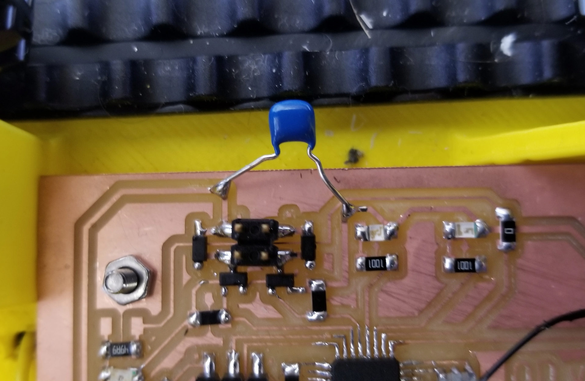
It took quite a bit of debugging to figure out the problem here. My first instinct, unsurprisingly, was that I’d the magic smoke I let out had killed some component on my board. If you look at the video, you can see that the debugging LED is flickering all over the place, while it’s supposed to still be blinking on and off every 100 ms. However, if I disconnected the motor, the light blinked correctly. So there’s some sort of power issue. After worrying that I had somehow fried part of my microcontroller, the solution turned out to be much simpler. By debugging with the oscilloscope, I could see that the power seemed to be flickering on and off even on my VIN trace (going directly from my power supply to my motors), without going through the microcontroller. My power was inconsistent, which is an easy fix with a capacitor. I had thought to put in a capacitor after the voltage regulator, but not on my higher current source. When doing the motor output for output devices week, we’d put in capacitors in parallel with the h-bridge, but for some reason it hadn’t occurred to me to do the same here. One more thing to change for the next version of the PCB.
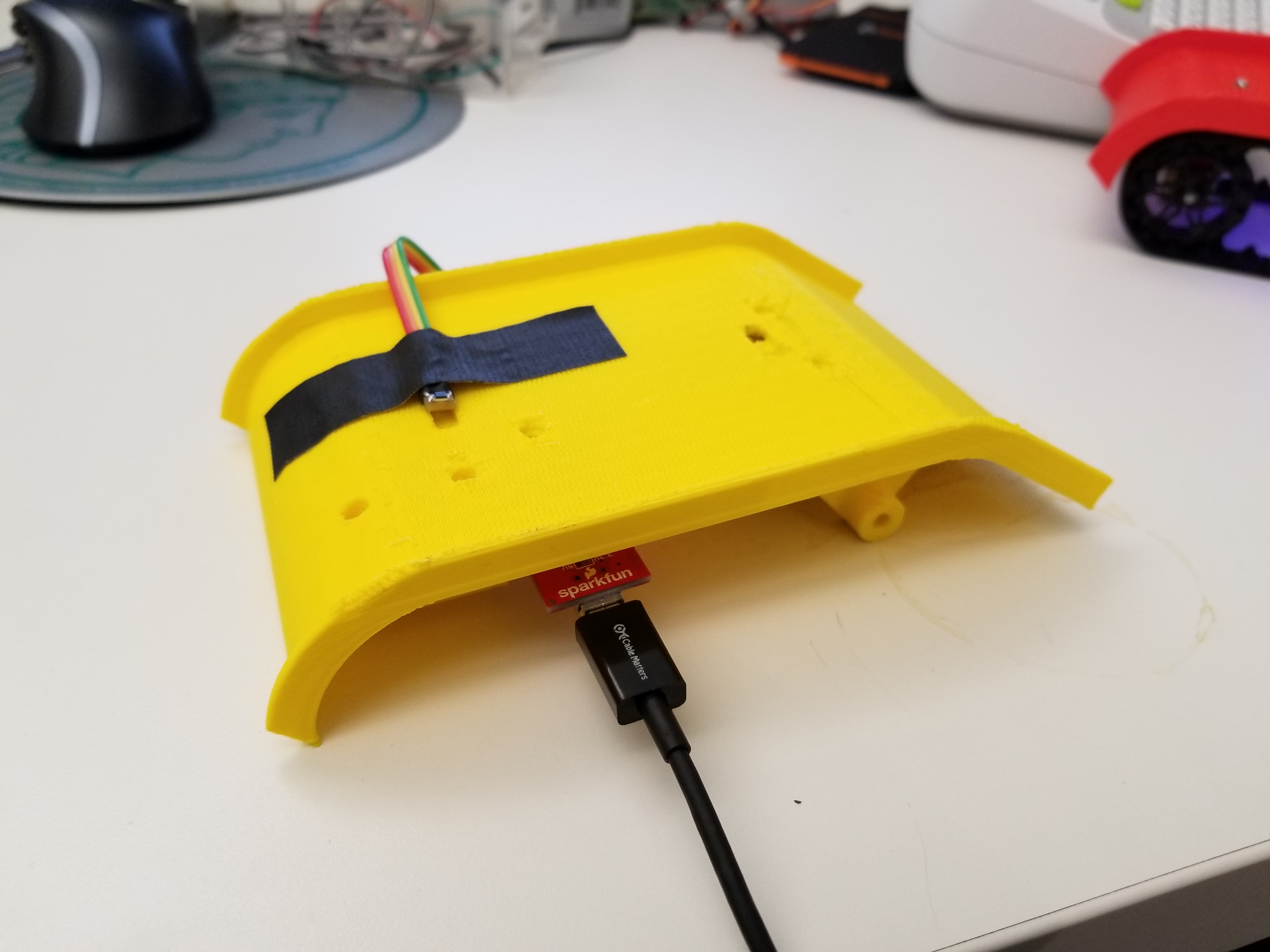
As a temporary solution to my lack of battery space, I taped a USB battery pack to the top of my robot so I could let it roam around. It’s not elegant, but look! I made a robot!
I also made use of the previous version of my chassis as a test of the robot’s climbing ability. It was able to get up and over the robot with a slope of 35 deg. This was before fixing the jittery motor problem, and while using a 5 V USB power source (the motors are rated for 6 V, and could probably handle a bit more), so I’m pretty confident that these motors are strong enough and the robots aren’t too steep. So I ordered 10 more of those motors and 5 more sets of brackets and tracks. At this point, I don’t really have time for many more rounds of ordering before the project deadline, so I’m taking a leap here on spending my advisor’s money. (And conveniently, Pololu has a holiday sale on now so I saved $45.)
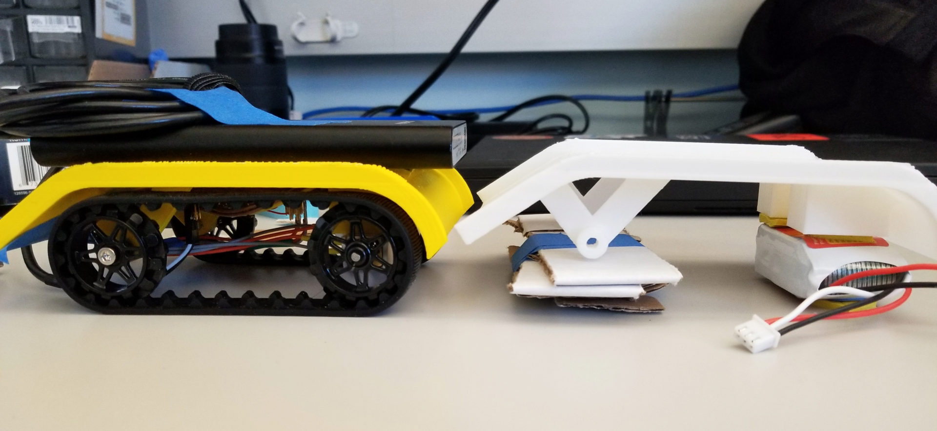
There remains one big issue with climbing, though: alignment. As shown in the picture below, if two robots are actually both on the same level, the back one won’t have any way to start climbing over the front one; the ramp is too high. If I extended the ramp longer and lower, this would limit the angle that the robot could climb itself, such that it would no longer be able to tilt high enough to climb other robots. My potential solution right now is a tail. I piece of thin, flexible rubber will be glued to the top of the ramp and extend past the back down to the ground. This will get under the wheels of the rear robot and allow it to climb without impeding the maximum incline the robot can achieve while climbing itself.
Robot v.1.2
Another weekend, another robot. On Friday I made v.1.2, with a new chassis and a new circuit board. Every time I make a new one, I think it’ll be the final version for my project, until I inevitably find a mistake.
The latest version of the circuit board included fixes for the capacitor across my input power, adding a switch, increasing the clearance between traces and the screw holes, and making the whole thing a little narrower so extra wires won’t hit the tracks. It doesn’t look much different. That tiny switch is useful, but dang, it’s so tiny and wedged in next to the wheel. I have to poke it with a pencil or screwdriver to flip it on and off.
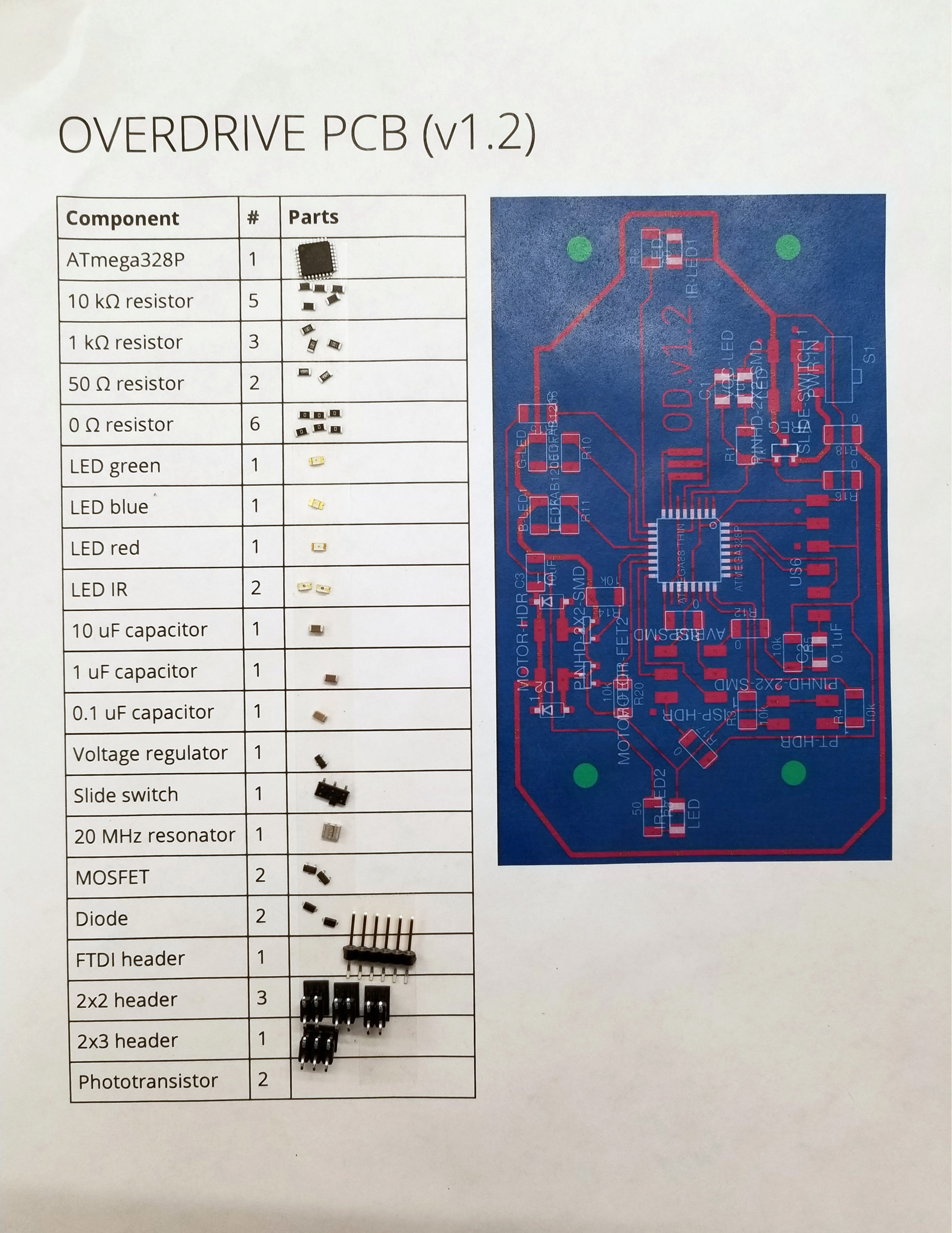
For stuffing my board, I borrowed an idea from Kevin to make the process easier and faster. (His project also involves making multiples of the same board.) I made a document with a table for all of my components (and how many), along with a picture of my board layout for assembly. Then I just add some double-sided tape and stick on all the parts before I start assembly.
I also printed a new chassis. The biggest changes here were to fix the track alignment issues in v.1.1. Part of this involved moving the rear wheel struts to the outside, which (combined with making the whole thing 5 mm wider) left space for the battery. I also widened the opening phototransistor wires to go through the top (though it turned out this still wasn’t quite wide enough – more drilling!). My initial tests also showed that the robot was rather… rambunctious, so I made the lip on the sides taller to hopefully prevent it from jumping and making a run for it.
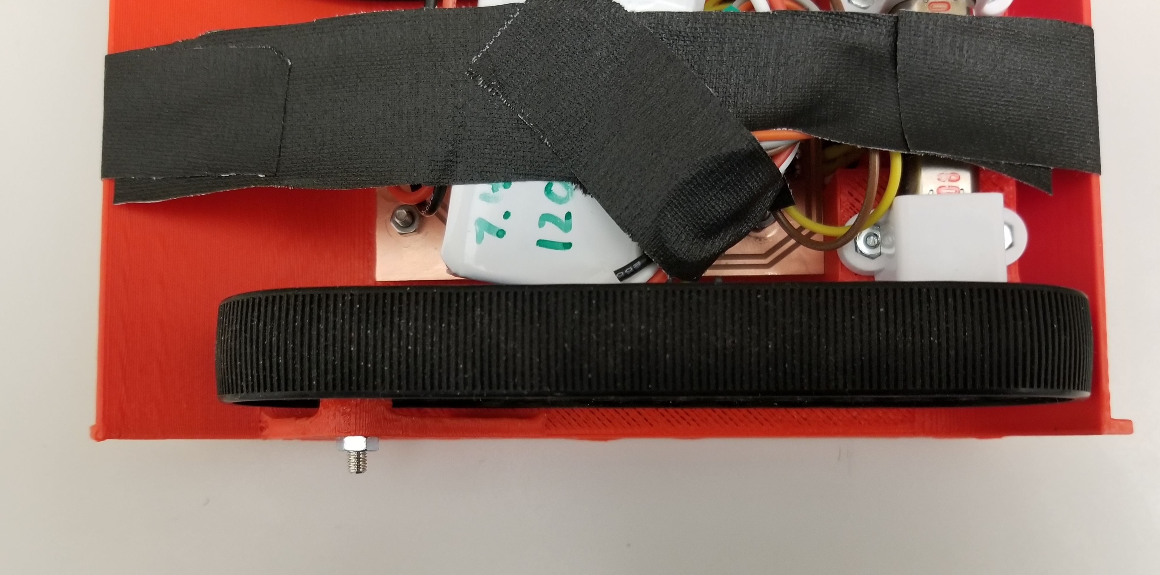
And the new version runs! It’s now powered by a 7.4 V LiPo battery and the speed of the tracks is controlled with pulse-width modulated signals. It’s now a lot smoother and more powerful, and it has no problem climbing up the back of the pseudo-robot with just a short rubber tail. You can also see in this video that I hadn’t figured a battery solution yet, so I just wrapped tape around the whole thing. Elegant, I know. Also, maybe it’s not the smartest idea to run this on a table where it can go flying off the edge.
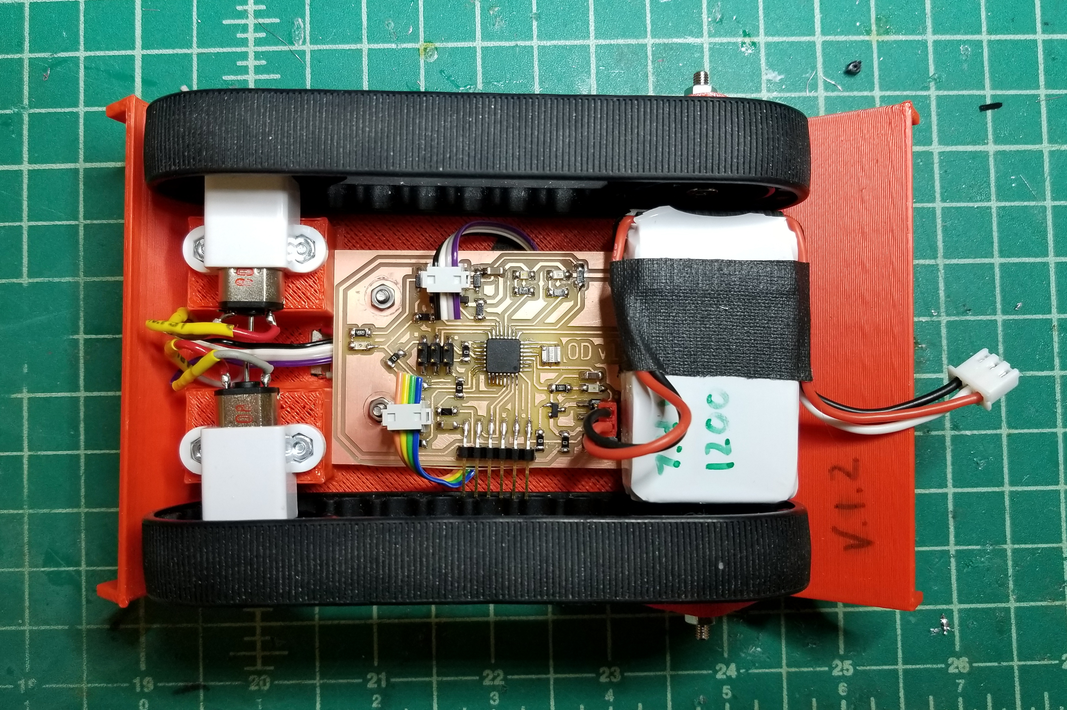
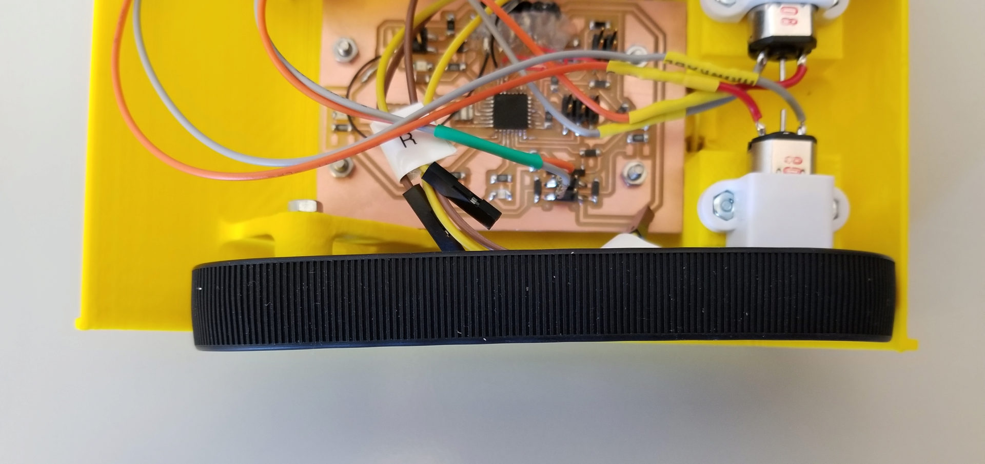
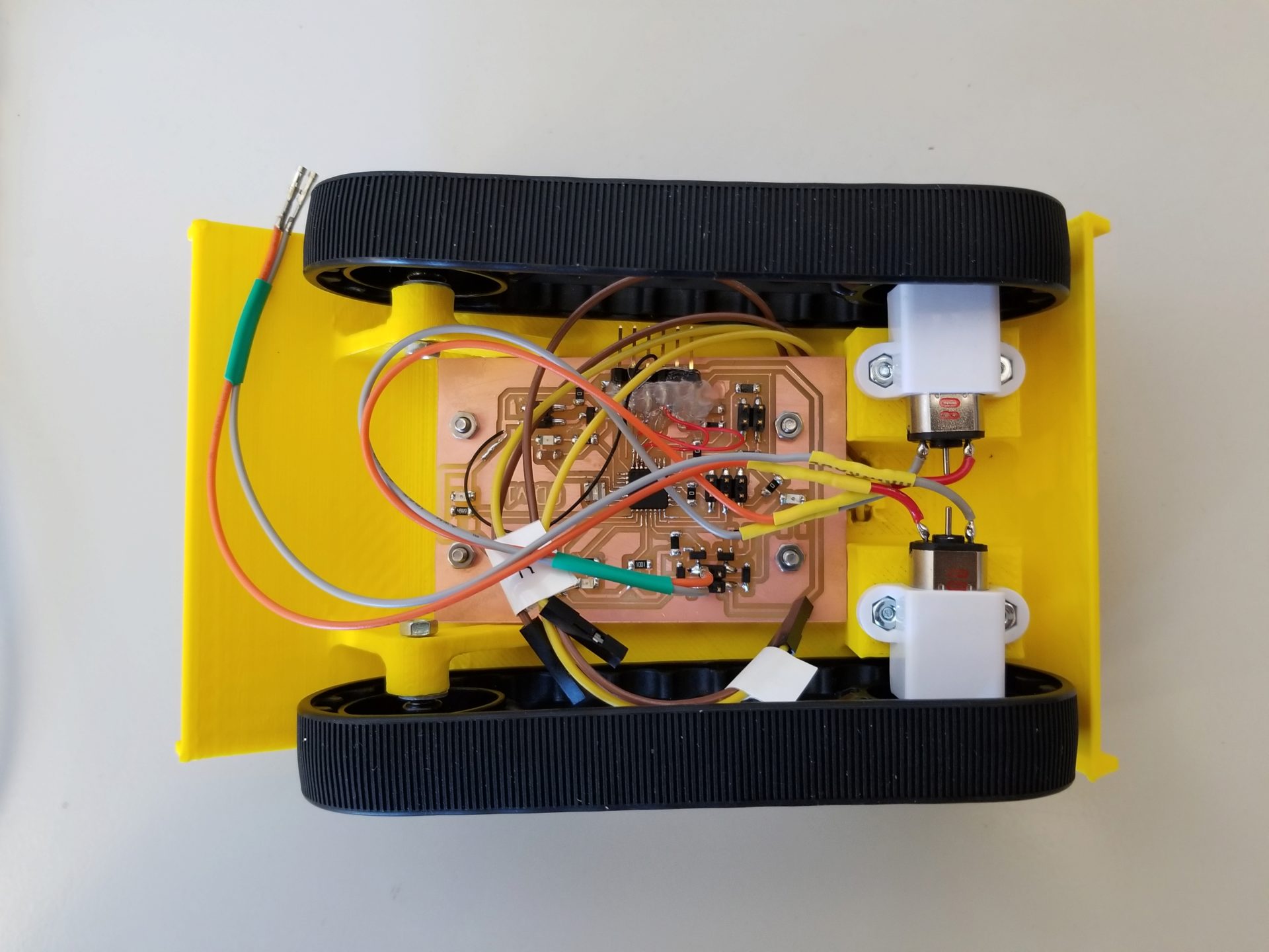
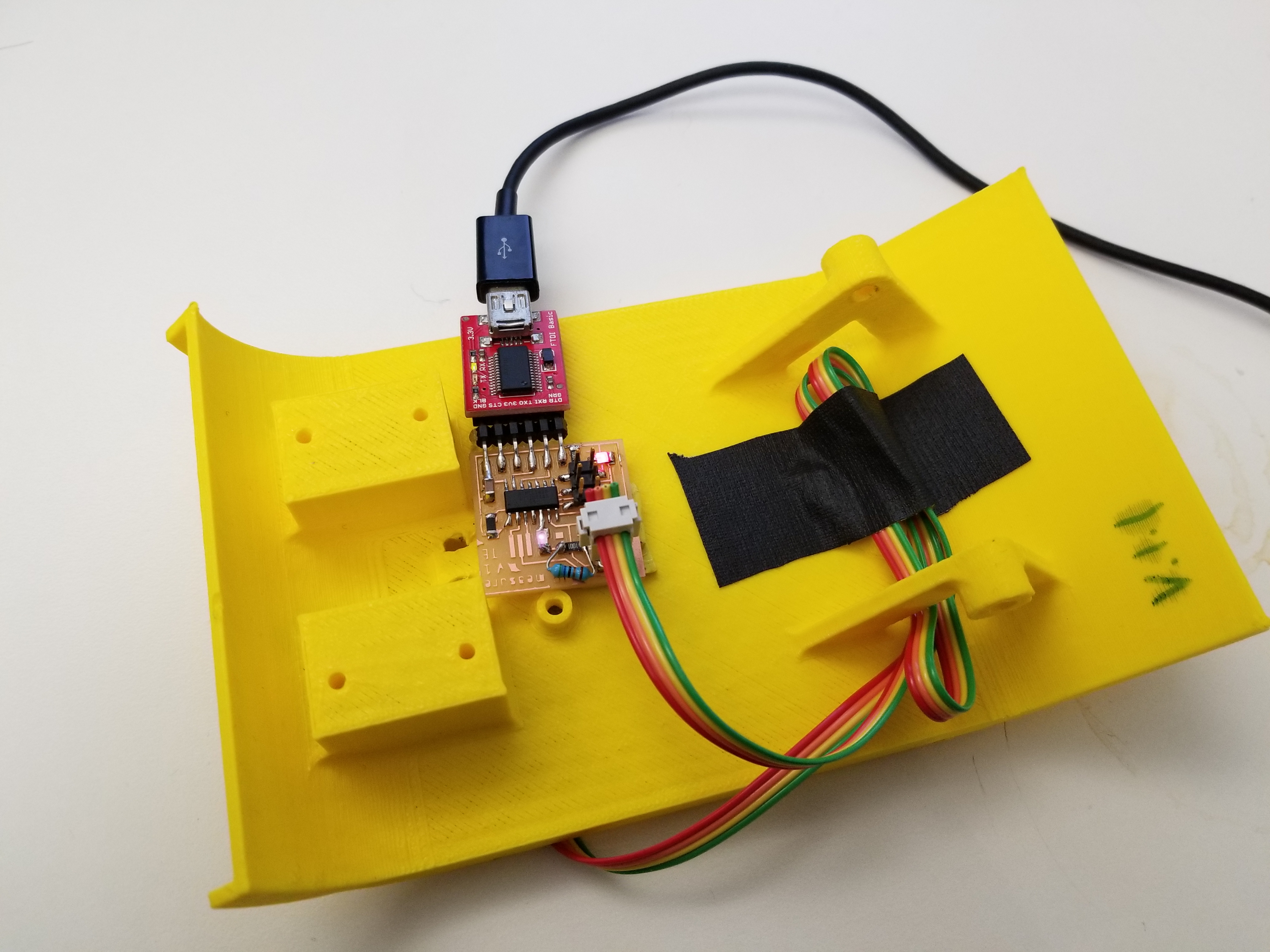
I invested my Saturday morning into the wiring on the underside, replacing the connections for my motors and phototransistors with 2x2 headers. This is so much cleaner and easier to work with, since I don’t keep having to fight around wires. In the picture to the right, you can also see that I’ve come up with some sort of solution for the battery. It just barely fits across the back, but with two important caveats: I had to remove the rear screws for this to fit, and it covers up the back infrared LED. I’m working out a design solution for the screw issue, but thankfully (as I’ll describe later), I think I can ditch the back LED from the robot altogether. I think my next iteration for the chassis will be yet another 5 mm wider, as well, because if the battery gets shifted even a little it’s hitting the tire tracks.

Most of my Saturday, though, was sunk into the depressing task of debugging my phototransistors. This should be straightforward, right? It worked so perfectly for my input devices assignment. But when I connected the FTDI header to my robot’s board, the readings out of the sensors were meaningless. The new challenge for me is that bugs can now also be in hardware, not just software. Sometimes, it’s both! After much frustration and comparisons (in both code and board) to my previous functional IR sensing, I realized the first problem: I hadn’t set up the circuit correctly. My phototransistor had one pin connected to ground, but I’d forgotten to connect the other end to… anything. I had to do some hacky soldering to get things rewired to connect to VCC (though luckily, the trace was nearby).
But it turned out that wasn’t my only phototransistor problem. After a few minor code bugs, I encountered one that I’m still stuck on: how to switch between analog input pins. The ATmega328P has a single MUX for analog-to-digital conversion, so it can only read from a single channel at once. That’s fine – I’ll just read the value of one sensor, change the ADMUX register to look at the other pin, and read again. Except that it’s apparently not that simple. It seems that the change doesn’t end up registered to do the readings, so at this point I’m stuck reading from only one sensor until I figure out the right things to Google.
In the meantime, to test how well the light detection works, I created a dummy robot out of the dead body of robot v.1.1 and my input device board. I stuck the phototransistor on top to test the LEDs on v.1.2, and the LED on the bottom front to test the phototransistors on v.1.2. This also helped me conclude that I could get away with ditching the rear LED. The rear phototransistor will detect the front LED as soon as a robot starts climbing, and the multiple phototransistors are able to detect it until it’s almost off the front. It also occured to me that having multiple IR LEDs could make things harder, since the robot on the bottom wouldn’t be able to distinguish the sources and could have a harder time determining movement.
Robot v.1.3
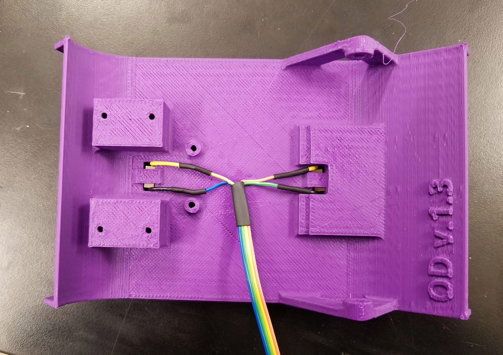
Two robots in one weekend! v.1.3 of the robot has relatively few changes, mostly related to mounting the PCB and battery on the bottom. I ditched the rear mounting screws and added a flat area to stick the battery to with the magic yellow tape. The rear of the PCB now rests on a ledge; it sort of press fits into place. I also finally got the sizing right for the phototransistor holes and refined my wiring procedure for them. Because I got rid of the rear LED, this also means my PCB is short enough to actually fit on a piece of FR4 when I mill it.
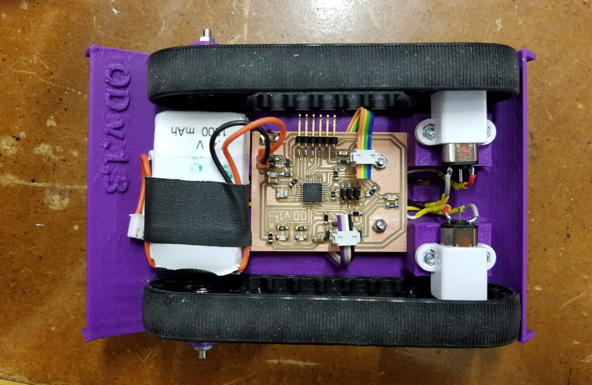
I wanted to get a sense of how long my battery will last when I’m running the robot. I connected a multimeter across the open switch to measure the current when the robot was running (with motors at 50% PWM duty cycle, the current power). With a \(1200~\text{mAh}\) battery and a measured current of \(0.42~\text{A}\), I expect a runtime of nearly 3 hours:
I should be able to get through the final exam on a single charge. If I’m not running them continuously, hopefully I can get through both the final and open house on that charge. (There’s no way I’m bringing 6 LiPo chargers along, so we’ll see how far a charge gets me.)
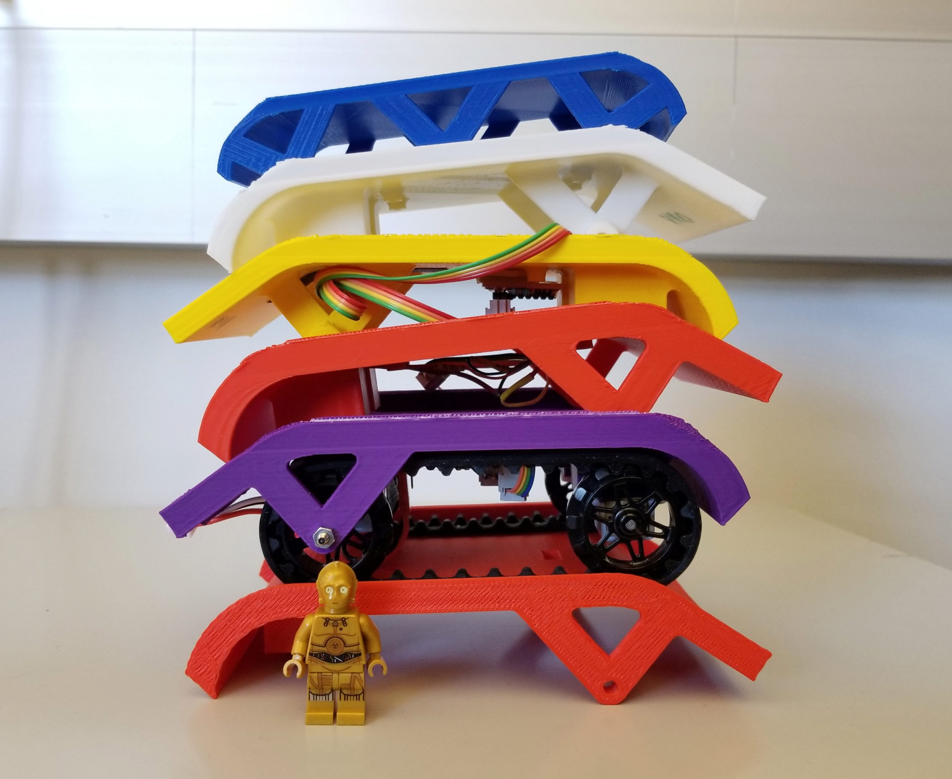
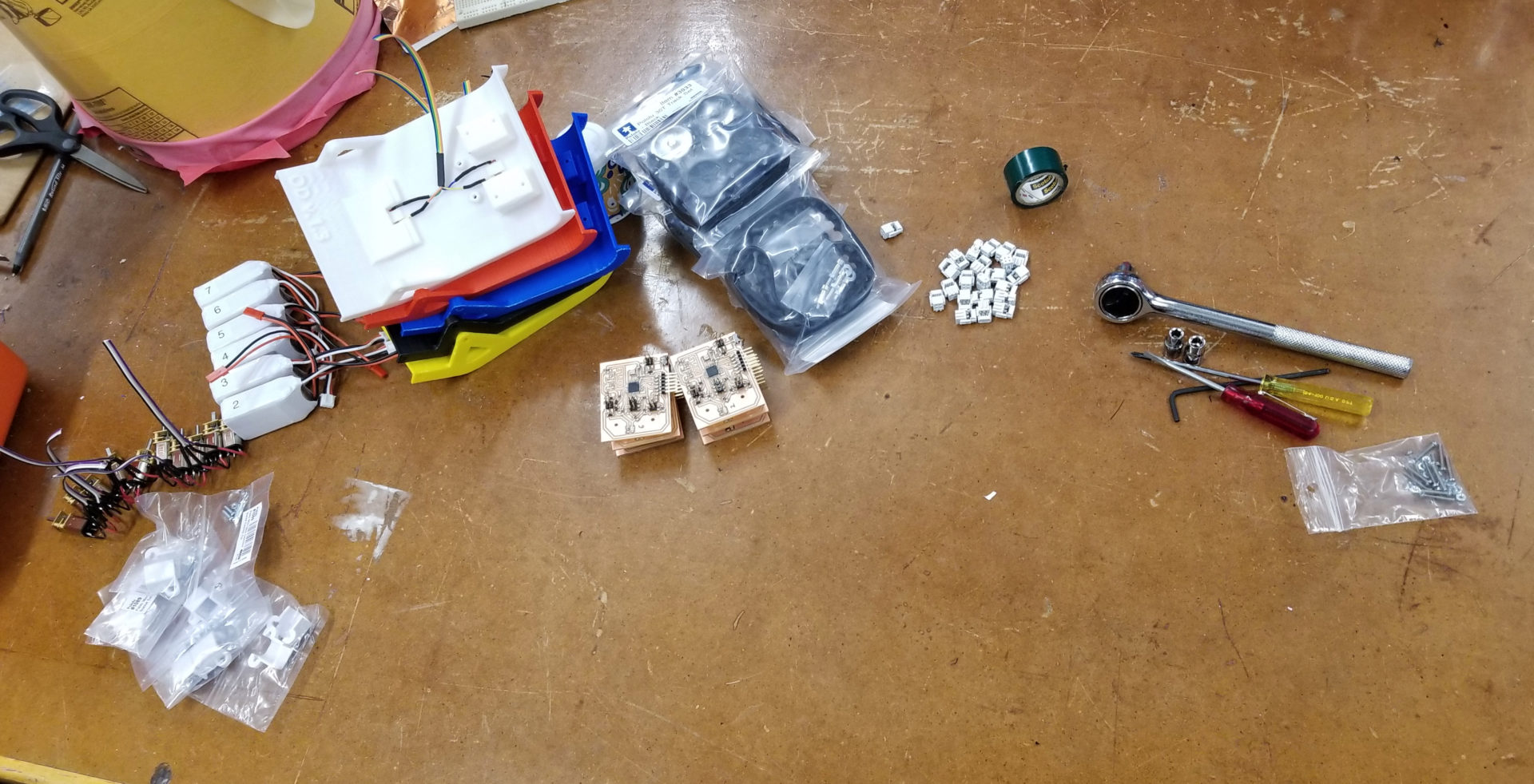
I’m now quickly accumulating a stack of robot bodies (Lego C-3PO for scale). I’m now locking in the chassis design for the final project; I don’t foresee any changes to it, so I’m starting to just make more of them in preparation for the arrival of all of my motors, wheels, and batteries on Wednesday. I’m not mass-producing my PCBs yet, because I still haven’t figured out the phototransistor issue. In case it’s a circuit design issue, I don’t want to make a bunch of boards with mistakes on them.
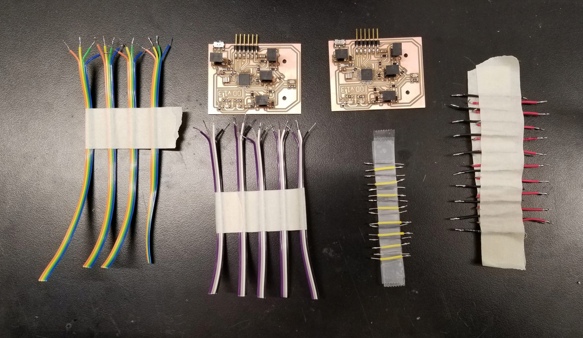
On Monday, there was much rejoicing, because I finally made my phototransistors both works. I don’t actually know what I changed or did that fixed the issue. It’s really feeling like black magic. After fiddling around with the code and commenting, uncommenting, and cleaning up the code, something finally made it work. I’m a little afraid to touch it now, though, for fear of re-breaking it. But this means my PCB is fine, which means it’s time to move into production mode. On Monday I milled and stuffed 2 PCBs, and cut, stripped, and tinned all 80 tiny wires I need to connect my motors and sensors. I also got my sheet of rubber for the ramps in the mail. Now I just keep refreshing the tracking pages in hopes that will make the batteries, wheels, and motors get here faster. (That’s definitely how it works.)
I also now have 3 total chassis printed for v.1.3. I decided to try changing the orientation. Previously, I was orienting it upside down when I printed, to reduce the amount of support material. For my 2nd copy of v.1.3, I printed it on its side. And dang, that looks so much nicer. Plus, it only take 5:30 to print instead of 6:30 – printing that large of a raft is slow.
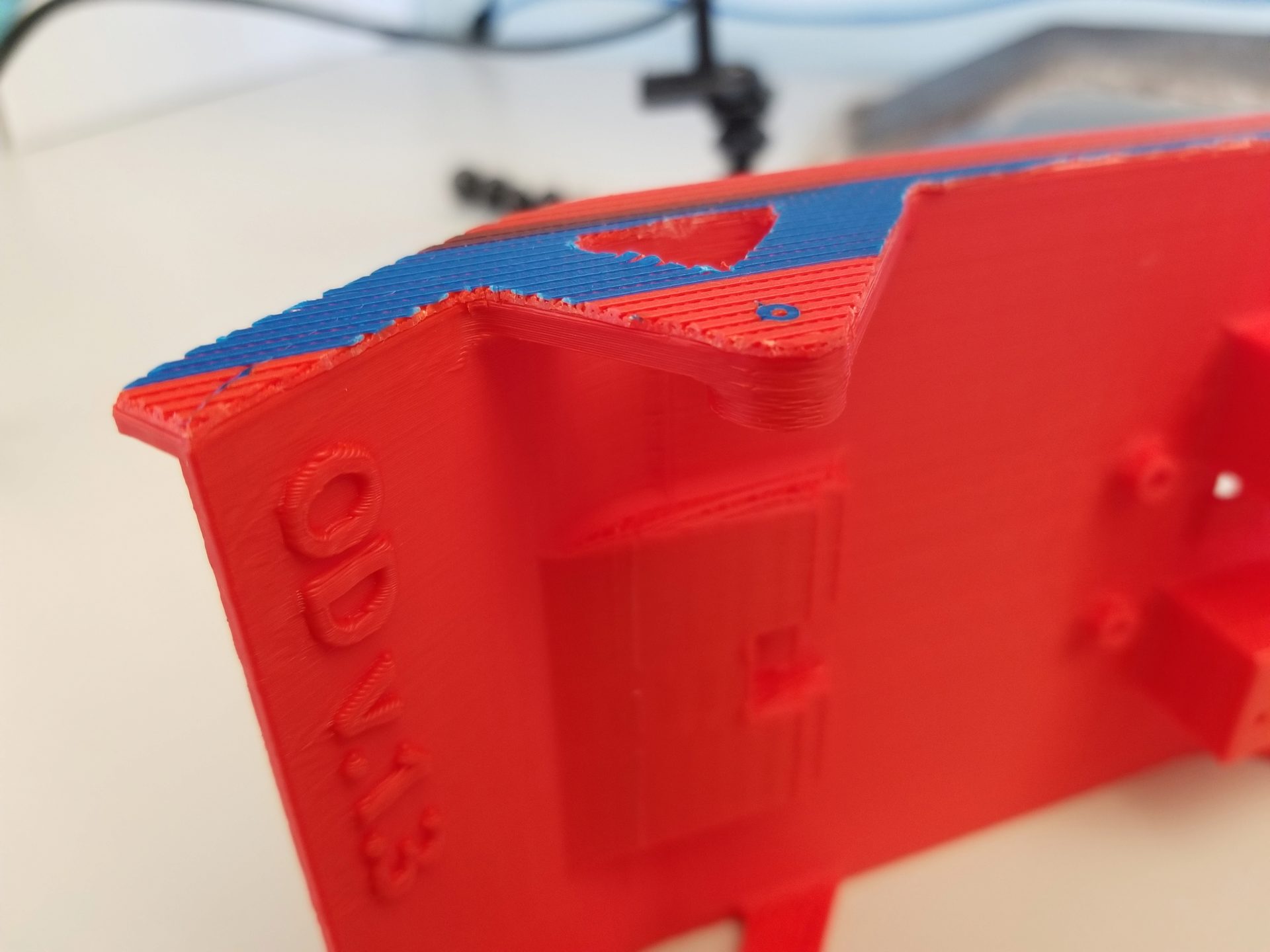
But I have one big problem: the raft. I printed it with the raft after all the dire warnings from the Sindoh software about the material not adhering to the bed. I ended up with a problem of the raft adhering to the part, though. This picture is after I took an exacto knife around all the edges to trim off the excess platform, because that platform material is never coming off the side of the chassis. It seems that the gcode didn’t leave a gap between the platform and the part.
So I checked the settings in the Sindoh software and found one that was set to “Airgap: 0.00”. Awesome, I’ll just change that to 0.20 and we’re in business! Nope. I printed my 2rd chassis during the day on Tuesday and had the exact same problem. Back to the exacto knife for the edges and the drill for the axle hole. I’ll see if Rob or one of the TAs can help me out tomorrow. After I enlist their help to figure out why I the yellow filament I want to use next won’t extrude, and why none of the spools of filament for the 3DWox printer seem to have the right chips with them! (Bonus: one of the two printers is broken right now, so now we all have to compete over the remaining printer, Hunger Games style. Oh man, it 3:30 AM I should go to sleep.)
Week 15: The Final Countdown
Production
As of Thursday, I am done monopolizing our section’s remaining non-broken 3DWox printer, and I managed to use all six colors! By printing sideways and switching from a raft to a brim for bed adhesion, I got the print time down to 4.5 hours for the last few chassis prints (from my original 6.5 hours).
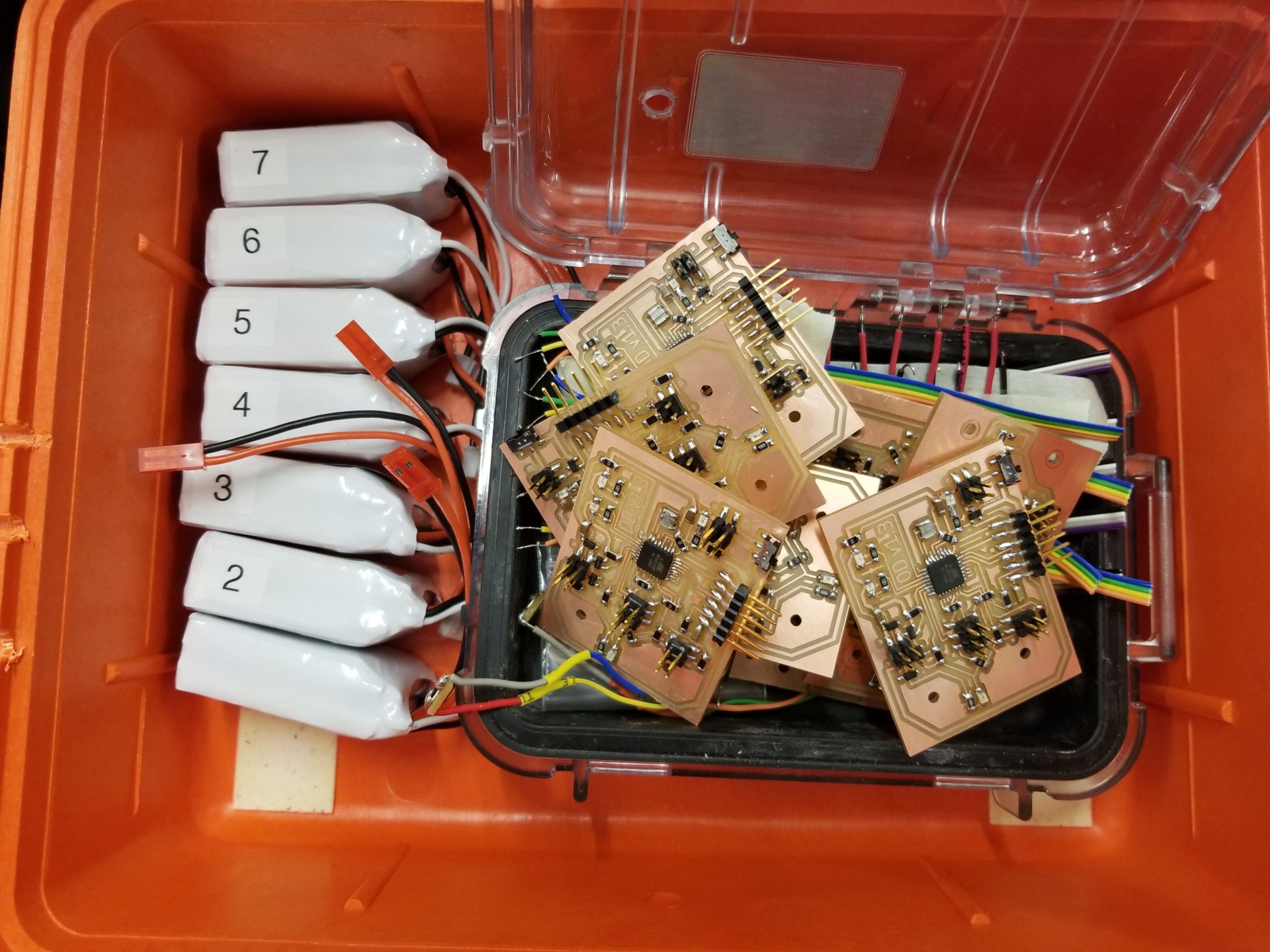
I also went on a milling and stuffing frenzy to get all 6 of my boards stuffed. And then while trying to check the current draw with the multimeter, I saw smoke and friend one of my boards. Afterwards when I switched it on, the motors and LEDs seemed to be always on at 50%. The program on my microcontroller still seemed to be running (because my debug LEDs still lit up correctly when I put the phototransistors near IR light), but I couldn’t program my board. I tried powering the board from USB or a different battery, replacing the voltage regulator, and finally replacing the microcontroller. That last swap let me program my board, but it’s still doing the same weird behavior otherwise. I’m at the point where it might be better to just make a new board altogether instead of continuing to debug the hardware on this and turn it into Theseus’s circuit board. (Update: I did make a new one. Two new ones, actually, in case I fry another board.)
My motors and wheels finally arrived on Thursday. I thought it would be painless at that point to get all of my robots put together and running, but I was optimistic. The problem mostly came from my boards, which I’d been too impatient to test when I made all of them. I had 2-3 boards that didn’t seem to power on at all, where the cause turned out to be a tiiiiny little spot where the mill didn’t fully cut through a trace between power and ground. Another board didn’t power on because the mill had gotten aggressive and ripped up the trace between my power input and the switch. And another one wouldn’t program, though that seemed to spontaneously resolve itself after much frustrated prodding with a multimeter. Plus there were 1-2 boards where I accidentally plugged in my battery backwards and fried the voltage regulator (though luckily there didn’t seem to be other damage). Then, after I’d proudly assembled my first robot, I realized that I’d soldered the left motor on backwards to all of my 2x2-header wires. Time to re-solder 5 sets of motors! By the time I got to my last robot, I was on a roll and getting pretty efficient.
And I made this video of my whole production process (culled from probably hours of footage, by the time I finished).
Video
I decided to make a slick video of my project, so I’ve been filming pretty everything on my phone. (Except programming, because that’s really boring to watch.) One part of this was taking a picture after every single solder I added to my PCB, which I want to turn into a stopmotion video. I set up my phone on a mini tripod and laid down spike tape to align my board. But there was still a little bit of variation in position, so I aligned all the images with a tool from Hugin:
align_image_stack -a aligned -C *.jpg
This will align all of the JPEG images in the current directory, and crop all of them to the same dimensions when it aligns them. The resulting images will be slightly smaller, but that’s fine since they’re still far larger than the 1920x1080 video that we’ll make. This outputs uncompressed TIF images, which are huge. So we’ll use imagemagick to resize, crop, compress (and in my case rotate) all these TIF images into manageable JPEGs. (You can change how it centers the cropping by changing to something like -gravity center.)
mogrify -resize '1920x1080^' -gravity north -extent 1920x1080 -rotate 180 -format jpg *.tif
We’ll turn these images into a 30 fps video using FFMPEG:
ffmpeg -framerate 30 -r 30 -f image2 -s 1920x1080 -i aligned%04d.jpg -vcodec h264 -crf 25 -pix_fmt yuv420p pcb-stopmotion-1x.mp4
And then we’ll slow it down (maintaining the frame rate for working for other videos):
ffmpeg -i pcb-stopmotion-1x.mp4 -filter:v "setpts=3.0*PTS" pcb-stopmotion-3x.mp4
I recorded video of my production process, then edited it together in Lightworks. I haven’t used it before, but it works on Linux, is sufficiently powerful, and doesn’t crash constantly (I’m looking at you, Kdenlive). The free version only exports 720p video, but for my purposes of small videos on this website, that’s good enough. After exporting, I compressed the resulting video (again) with ffmpeg. I used the two-pass approach from this site to compress to a target file size. My bitrate to achieve this was determined by the target file size (here, 20 MB):
Then I feed this to ffmpeg:
ffmpeg -y -i production-v1.mp4 -c:v h264 -preset medium -b:v 1200k -pass 1 -an -f mp4 /dev/null && \
ffmpeg -i production-v1.mp4 -strict -2 -c:v h264 -preset medium -b:v 1200k -pass 2 -c:a aac -b:a 128k output.mp4
Remote Control
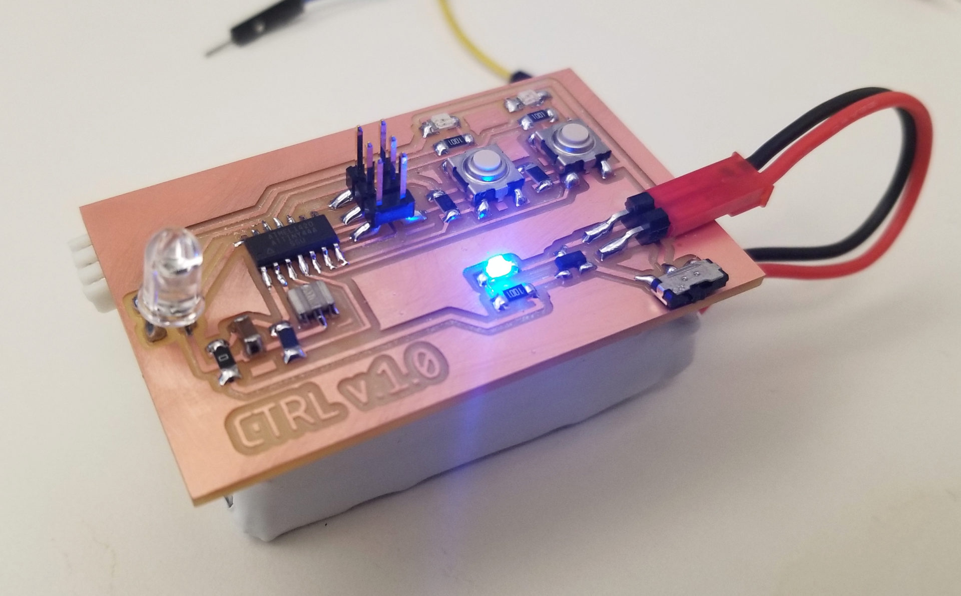
I’m finally getting back to my networking week work: sending a signal to start or stop all of the robots from a remote controller. I made a remote control board with two buttons and corresponding indicator LEDS: one two send a start signal, one to send a stop signal. It also has a bigger IR LED to send the signal.
I defined the values of a byte that correspond to start and stop signals and redirected Neil’s put_char() function to an LED instead of the FTDI header RX pin. I tested this out blinking accordingly on my controller: if I press the start button, I make the other LED blink with the stop byte signal. So that I could tell what’s going on, I slowed down the bit delay to 100 ms. It took some fiddling with my old Hello World button interrupt code to get it working for two buttons and play well with the blocking signal sending. All I need to do now for the controller is switch to sending that signal to the IR LED, then verify with my phototransistor board and an FTDI header that it’s properly sending the IR signals, and they can be picked up by my phototransistors. Here, I’m sending a byte with the other colored LED when I press the start/stop buttons:
The controller turns out to be easy, compared to receiving the signal. Originally I thought I could similarly adapt the get_char() function, but this has two big problems. First, that’s assuming reading from a digital pin, whereas my phototransistor input is analog. Second (and by far a harder issue) is that get_char() is a blocking function; with the line while (pin_test(*pins,pin));, the whole program will wait on a high signal from the pin. This doesn’t work for me. It looks like I need to use interrupts to check the pin, and deal with ADC for my input.
My new attempt is going to be attempting to steal (er, I mean, repurpose) the method the Kilobots use to receive IR messages, since the Kilobot library is publically available and they conveniently also use the ATmega328P. The Kilobot library handles this with a timer interrupt that checks for bits. In the interest of supply-side design, though, I’m going to leave this to the side for now and in the meantime opt for a stupid-simple approach: if the light is above a high threshold (higher than you get from a robot passing overhead), the robot will stop moving. If it detects a high light again after a certain timeout delay, it’ll start moving.
After sleeping on it, I’ve got a new hacky approach: reuse my timers. I already have a timer in my robot code for setting ticks (a downscaled timer of ~76 ticks per second for tracking things in my main loop like robot velocity). And I’m using a timer to check for button changes in my controller code. Both of these are running on 20 MHz external resonators (although with different microcontrollers). If I get them to have matching clocks, I think I should be able to send values using the interrupt on the controller (setting the LED pin high and low) and read values using the interrupt on the robot (looking at the value from the phototransistor that’s read every cycle in the main loop). I don’t know how well this will work.
I rewrote both sending on the controller and receiving on the robot to handle messages in the same timer interrupt, changing the LED every 5 ticks (i.e., every 5 interrupt cycles, so it’s slow enough that I can see whether it’s working). I’m sending a single alternating byte with a start and a stop bit from my controller, and turning on and off the blue LED based on the IR level (above or below threshold) on the front phototransistor. It works!
But interpreting that into a byte is trickier, because I have to get the right framing. The byte detection code in the interrupt will start when it first detects a bit, assuming this is a start bit. But how do I know whether this is actually a start bit, or a bit partway through a message?
Collective Movement
Alright, I still need to do something to make the robots move together. As a first pass: if a robot detects IR light on either phototransistor, it stops moving. It’s not quite a moving walkway or a group speedup, but it’s tractable for the time remaining.
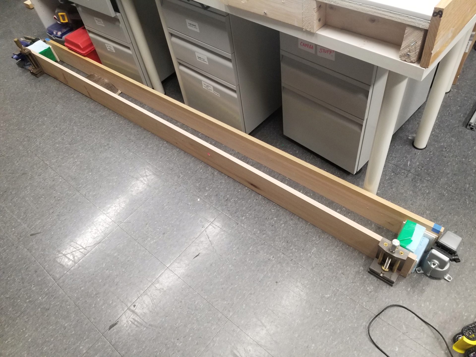
First, a sanity check: Can I get a robot to climb over a group of stationary robots (and that ramp from last week)? Because the robots climb too well and like to drive off the side of each other, I’m doing everything in a canyon made of boards.
For now, the robots stopped whenever they sense IR, and start moving again 2 s after their last IR detection. This means that if I hold my remote control above the robots while setting up, I can get them all positioned, take away the controller, and have them start. But it doesn’t work that nicely, in large part because the IR LED on my remote isn’t really powerful enough to cover all the robots at once. So some will start and then get away. It’s like herding cats. This picture to the left is how I keep them from all running away while between runs.
I can reduce the threshold for detecting IR, but in the absence of a brighter IR LED, I still need a more robust solution. I’m adding a state to the robots. Now, once they’re turned on, they won’t start moving until they detect IR for the first time. I’m now experiencing the thrill of creating reprogramming all of the robots individually with every change that I make.
The added state solution ended up being fairly straightforward. In order to get the robots to stop (and not have to turn them all off and on again for another run), I also added a timer that they’ll return to the initialization state after running for 15 s.
And now (drum roll, please) it works!
Plus, on occasion they even end up aggregating to help each other escape. (This made my advisor really excited.) In this particular case, the escaping robot isn’t doing so well once it gets out, but hey, it’s out!
Future Work
This is what I want to do with the robots that I didn’t accomplish for the project.
- Use more powerful (higher gear ratio) motors. This should mean that for the same duty cycle, robots can produce more torque to climb better and will have a lower speed that will improve aggregation.
- Make infrared serial communication work to remote control the state of the robots.
- Make robots slow down when underneath another robot, rather than stop completely (requires detecting movement of overhead robot).
- Create a longer track or figure out how to make them move straighter (and not drive off the sides of each other) so I can look at aggregation over a longer timescale.
Parts and Files
Robot Components
Prices for electronics components are taken from the Fab Lab inventory list. This does not include the cost of 3D printing filament.
| Item | Quantity | Price per unit | Total Price |
|---|---|---|---|
| Motors | 2 | $16.95 | $33.90 |
| Extended motor brackets | 1 | $4.95 | $4.95 |
| Tracks | 1 | $14.95 | $14.95 |
| Battery (7.4 V, 1200 mAh) | 1 | $9.99 | $9.99 |
| Rubber sheet (1/16”, 12”x12”) | 1/12 | $11.96 | $0.99 |
| ATmega328P | 1 | $2.87 | $2.87 |
| 10 kΩ resistor | 5 | $0.01 | $0.05 |
| 1 kΩ resistor | 3 | $0.01 | $0.03 |
| 50 Ω resistor | 1 | $0.01 | $0.01 |
| 0 Ω resistor | 5 | $0.01 | $0.05 |
| Green LED | 1 | $0.15 | $0.15 |
| Blue LED | 1 | $0.13 | $0.13 |
| Red LED | 1 | $0.13 | $0.13 |
| Infrared LED | 1 | $0.36 | $0.36 |
| 10 uF capacitor | 1 | $0.18 | $0.18 |
| 1 uF capacitor | 1 | $0.07 | $0.07 |
| 0.1 uF capacitor | 1 | $0.12 | $0.12 |
| 5 V voltage regulator | 1 | $0.32 | $0.32 |
| Slide switch | 1 | $0.84 | $0.84 |
| 20 MHz resonator | 1 | $0.43 | $0.43 |
| MOSFET | 2 | $0.34 | $0.68 |
| Diode | 2 | $0.17 | $0.34 |
| FTDI header | 1 | $0.71 | $0.71 |
| 2x2 header | 3 | $0.66 | $1.98 |
| 2x3 header | 1 | $0.60 | $0.60 |
| Phototransistor | 2 | $0.15 | $0.30 |
| TOTAL: | $75.13 |
Remote Control Components
| Item | Quantity | Price per unit | Total Price |
|---|---|---|---|
| Battery (7.4 V, 1000 mAh) | 1 | $7.99 | $7.99 |
| ATtiny44 | 1 | $1.18 | $1.18 |
| 10 kΩ resistor | 3 | $0.01 | $0.03 |
| 1 kΩ resistor | 3 | $0.01 | $0.03 |
| 50 Ω resistor | 1 | $0.01 | $0.01 |
| 0 Ω resistor | 1 | $0.01 | $0.01 |
| 1 uF capacitor | 1 | $0.07 | $0.07 |
| 20 MHz resonator | 1 | $0.43 | $0.43 |
| Red LED | 1 | $0.13 | $0.13 |
| Green LED | 1 | $0.15 | $0.15 |
| Blue LED | 1 | $0.13 | $0.13 |
| Infrared LED | 1 | $0.36 | $0.36 |
| 5 V Voltage regulator | 1 | $0.32 | $0.32 |
| Slide switch | 1 | $0.84 | $0.84 |
| Button switch | 2 | $0.74 | $1.48 |
| 2x header pin | 1 | $0.24 | $0.24 |
| 2x3 header | 1 | $0.60 | $0.60 |
| TOTAL: | $14.00 |
Code
This is the code as of the project presentation. There are some parts of the code that aren’t used (e.g., serial IR communication).
Design Files
These are the versions (v.1.3) used for the final project.