Week 8. Input Devices
Material: Attiny44, HC-SR04 ultrasonic sensor.
I fell behind a week because of my wedding, so I decided to make something that could go with my output device week as well.
I used the ATtiny44 and added the HC-SR04 as my input device. Taking Neil’s ATtiny45 as an example. It just needs 4 pins: GND, VCC, ECHO, and TRIG. I randomly selected two pins from the ATtiny to map to ECHO and TRIG.
Here is the pin diagram. I always get them confused.
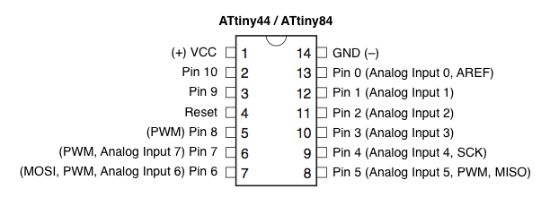
I made the outline and trace using Eagle. I accidentally modified the board schematic and changed some of the components before taking a screenshot of the device. All I have is the .png file of the trace.
Trace
Outline
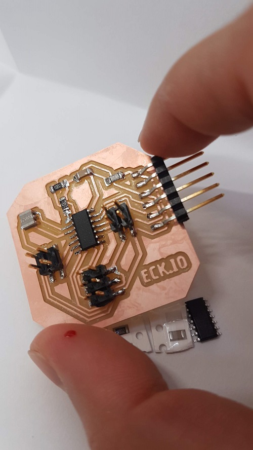
The milled board without any issue.
Populated with all components. My own creation stabbed me.
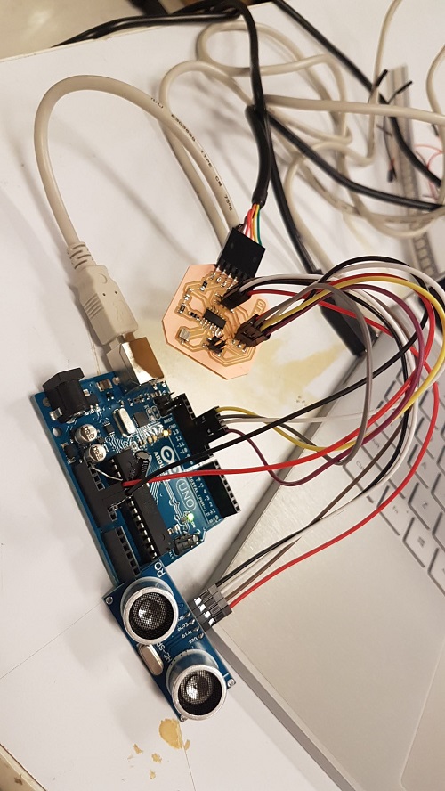
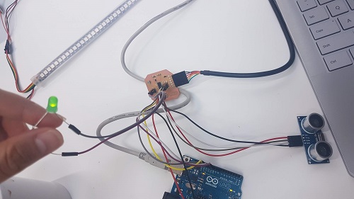
HC-SR04 connected to the board. I used an Arduino UNO as the programmer and the Arduino IDE. Followed my programming week6 documentation. 1. Connect ISP pins (MISO, MOSI, RST, VCC, GND, SCK) from Arduino to the ATtiny44 board. - Arduino Pin 13 (or SCK of another programmer) to SCK of ATtiny44 - Arduino Pin 12 (or MISO of another programmer) to MISO of ATtiny44 - Arduino Pin 11 (or MOSI of another programmer) to MOSI of ATtiny44 - Arduino Pin 10 (or RESET of another programmer) to RST of ATtiny44 - GND to GND - VCC to 5V in Arduino. 2. Connect FTDI cable to the ATtiny44 (not needed if it is just uploading code). 3. Connect the HC-SR04 to the ATtiny44 board: GND, VCC, ECHO, TRIG. 4. Upload ArduinoISP example code to the Arduino UNO in order to use it as a programmer. 5. Write Arduino Sketch to make the HC-SR04 calculate the distance in cm. This code was tested on the Arduino UNO. 6. Modify the code with the corresponding ATtiny44 pin for ECHO and TRIG. 7. Upload code to ATtiny44 using the Arduino UNO as programmer. COM port should still be the Arduino Uno Port.
Here is the electronics:
I placed a LED in one of the other IO pin to give me a visual feedback of what is going on. I tried using the terminal, but it did not work out. Based on my sketch, I can see that the board electronic is good. However, my code failed to do what it was supposed to. I changed the clock to use the 20MHz and the sensor was even worse. It did not react at all. With the internal 8MHz, it did turn on the LED at a random distance from the sensor, which tell me that the connections are correct. I need to fix the code, but first, I need to review everything to do with microcontroller: registers, clock, C programming.
2x speed up video of HC-SR04 kinda working.
Update
I realized used the oscilloscope to figure out the timing issue I was having. It was definitely the clock. Later on, I made another simple board for the HC-SR04 for the interface week. Realized that the issue was not burning the bootloader from the Arduino IDE, thus, it was compiling at a different clock speed. See interface week