Networking
Files: audio_interface.sch audio_interface.brd audio_interface_2.sch audio_interface_2.brd serial_cpp lufa (see Demos/Devices/ClassDriver/VirtualSerial)
This week we’re making machines talk to each other. I’ve used I2C before, so I’m curious to venture into the wonderful world of USB.
Board Design
For part of my final project I want to make my own USB audio recording device. So I’ll try to develop all the necessary electronics this week. I have the analog circuitry I need from inputs week. But I don’t have a board ready to go with a USB-capable microcontroller (bit-banging will not suffice, since I need the CPU to be available for audio processing). I’ve heard that LUFA is much nicer than ATMEL’s own USB libraries so I’ll try to use that. I’d like to use an XMEGA board, since they are fast, have a good amount of memory for audio applications, and I’ve used them recently. LUFA’s XMEGA support is technically experimental, but people have been using it since 2013. So I think it should be ok.
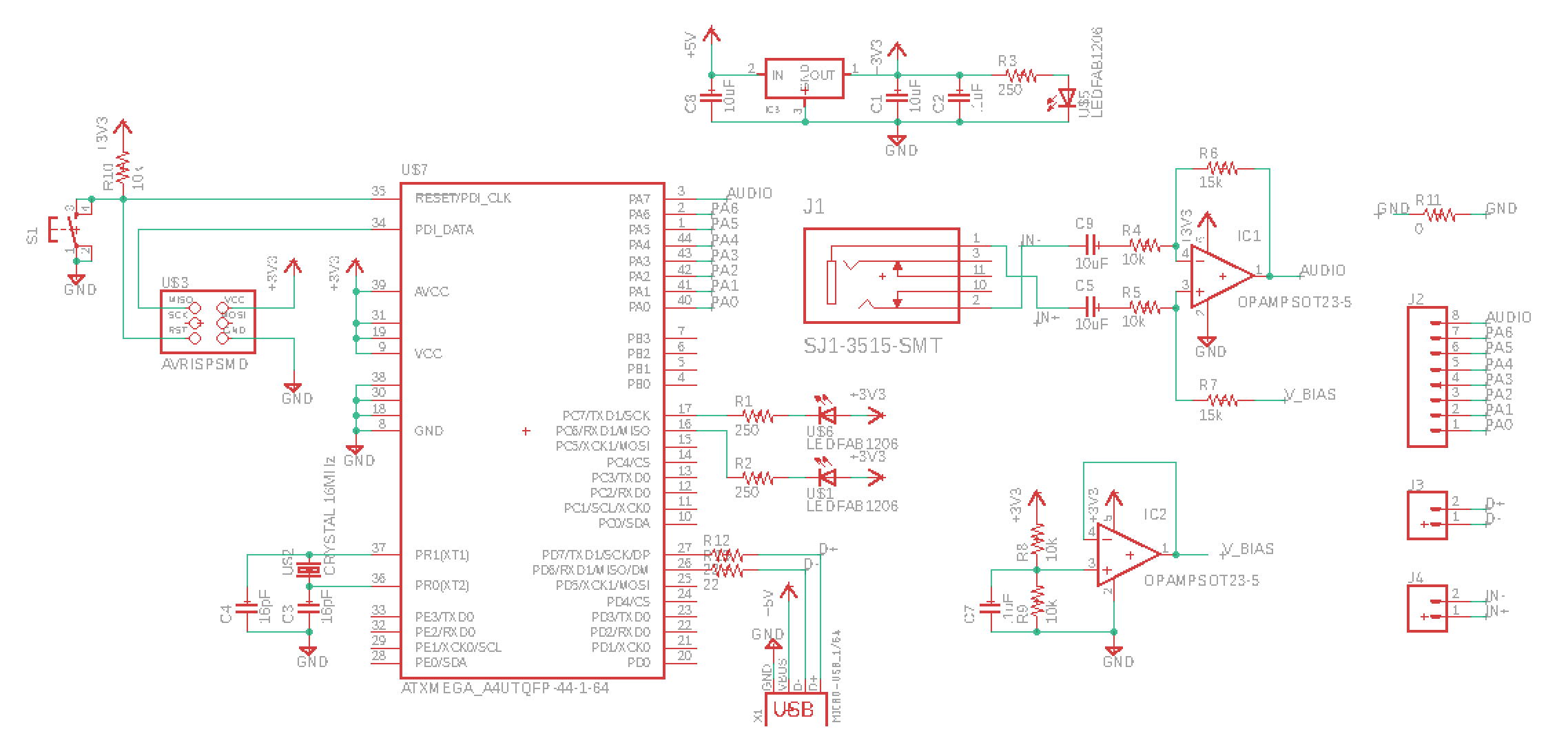
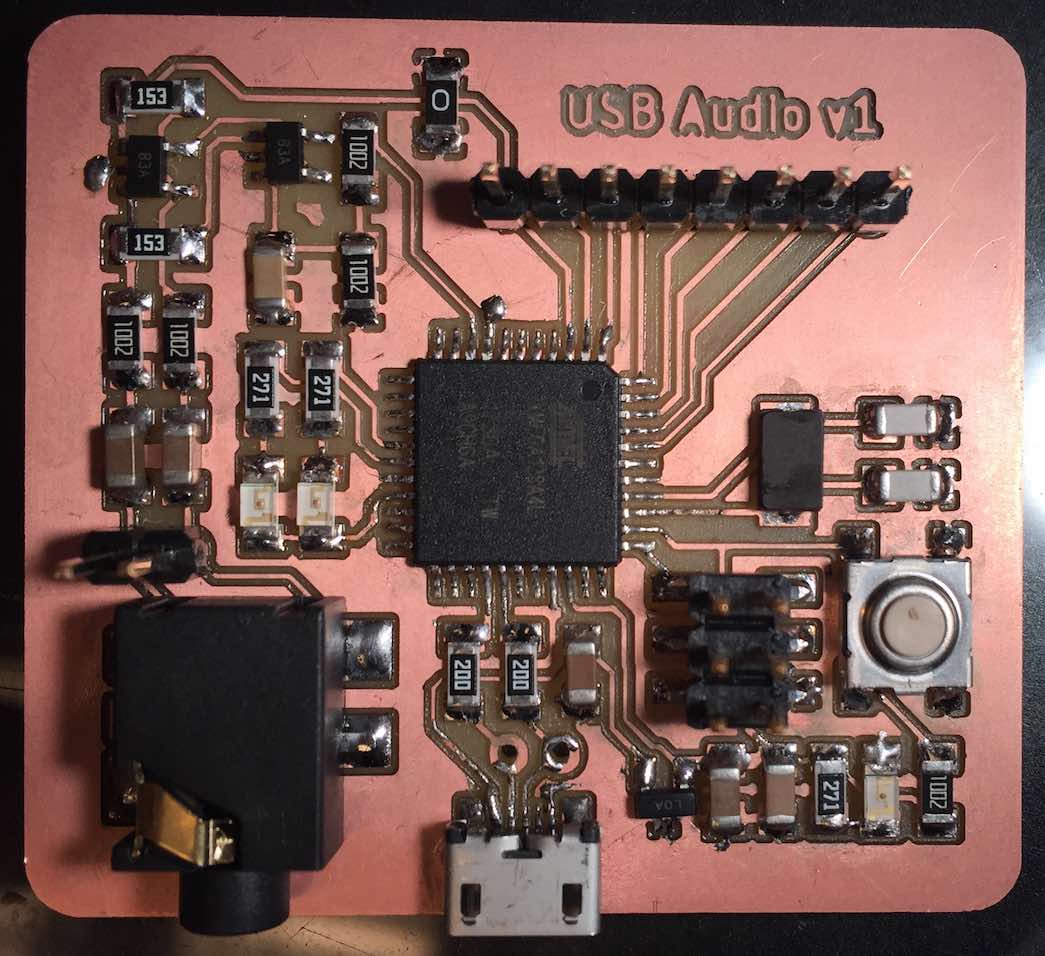
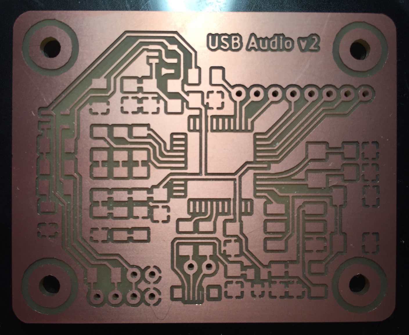
On the left I have my microcontroller. I’m using an external 16MHz crystal to give it an accurate clock signal. High speed USB 2.0 requires a 48MHz clock, which I can get by multiplying the crystal’s output by 3 using the XMEGA’s phase locked loop (PLL). On top I have my power section, including a regulator to bump USB’s 5V power down to 3.3V, some filtering capacitors, and a power indicator LED. The two circuit groups with op-amps together amplify and bias the audio input, as I learned in inputs week. Finally I have some headers that provide convenient debugging access to certain signals, and a 0-ohm resistor I needed to connect all my ground signals.
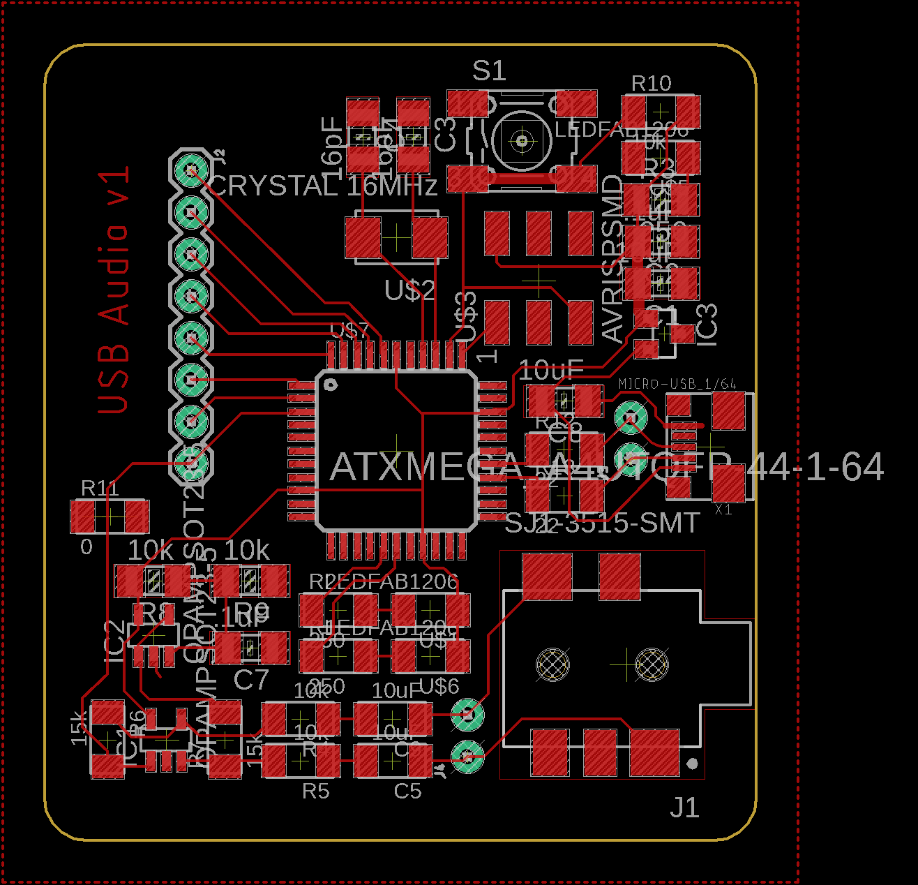
Laying out the board took a long time, since this is the most complex circuit I’ve designed from scratch. I’m using thinner traces than before, so that they can reach all the XMEGA’s pins without shorting and so that I can route multiple traces under a single 1206 component. I kept the USB signal traces as short as possible. One open question I have is what to do with the USB connector’s shield. Plenty people have asked this question online, but the answers are split between grounding it directly and connecting it to ground via a capacitor and a large (ex 1MΩ) resistor. I don’t yet have the expertise to know which makes more sense in this situation. This document looks like it might help, but I haven’t had time to read it all yet.
Fabrication
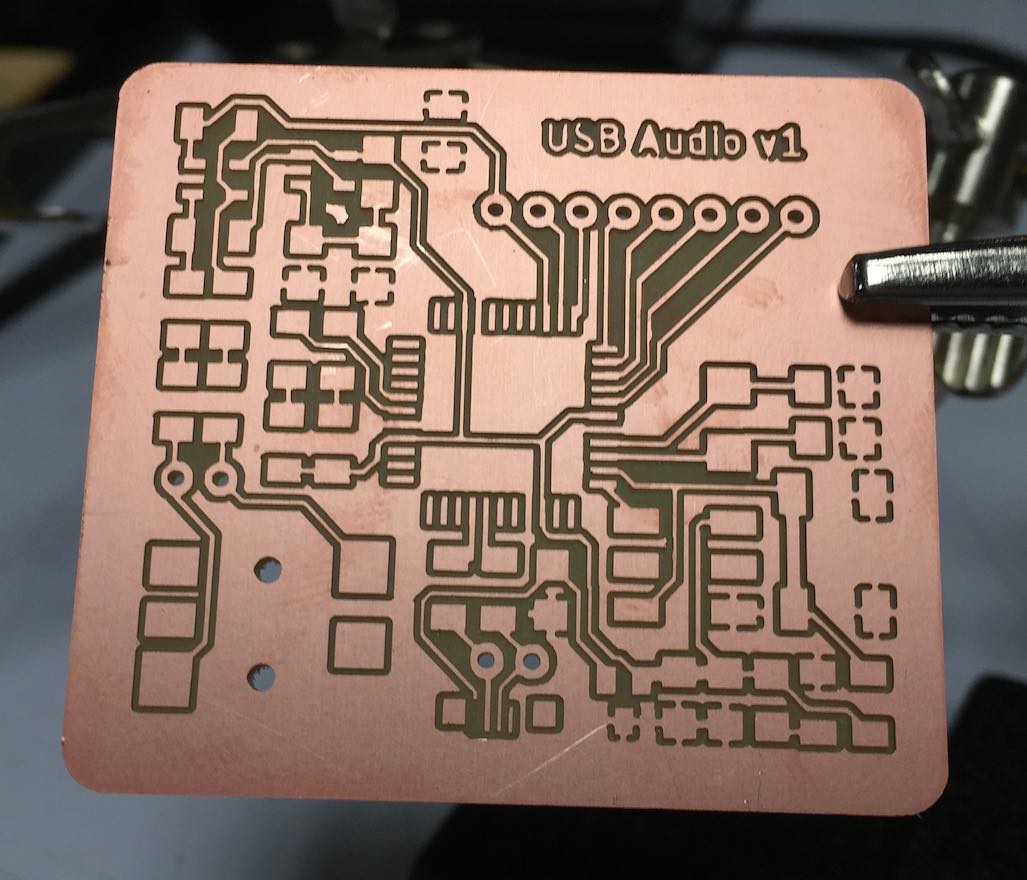
I milled the board on a Roland SRM-20. For the most part the smaller traces worked fine. However the end of the power trace for the USB port did get pulled off. (The same is true for part of the ’S’ in the text, but that won’t require any jumper wires.)
I soldered the XMEGA and the USB connector first, since I knew jumping the USB power wire and dealing with the tiny XMEGA traces would be the trickiest tasks. The XMEGA’s leads are smaller than anything I’d soldered before, but it still went fine. Most of them I soldered individually, but in a few places I globed pins together and later removed the excess solder to unshort them. Generous amounts of flux were essential, since I used a very fine gauge of solder that doesn’t have a flux core. To connect the USB power, I took a small piece of wire and used it to jump directly from the USB connector pin to the trace. It was so short that it was almost impossible to solder one side without melting (and thus destabilizing) the other, but eventually I got it to stick in place with good quality joints on both sides. (In the photo below it looks like it’s shorted to the USB plug chassis, but the jumper wire is safely above the leftmost lead.) After these I soldered on the minimal number of other components to get the power indicator LED working (ok, the crystal wasn’t necessary but I had already taken it out).

From here it was a routine soldering job.
Software (First Attempt)
I started by flashing it with an empty hello world program, to verify that it could be programmed at all. Then I cloned LUFA and started trying to adapt an example to work for my board. Unfortunately, disaster struck: I accidentally tore off the USB connector. I knew this was a risk, since I decided to delay soldering the USB jack shield until I knew what to do with it. The cable I used required fairly high force to remove, though, so I think once I plugged it in the board’s fate was sealed. You can also see that leftover flux greatly sped up oxidation, leaving spots of green copper oxide.

I figured it was worth a shot at repairing.
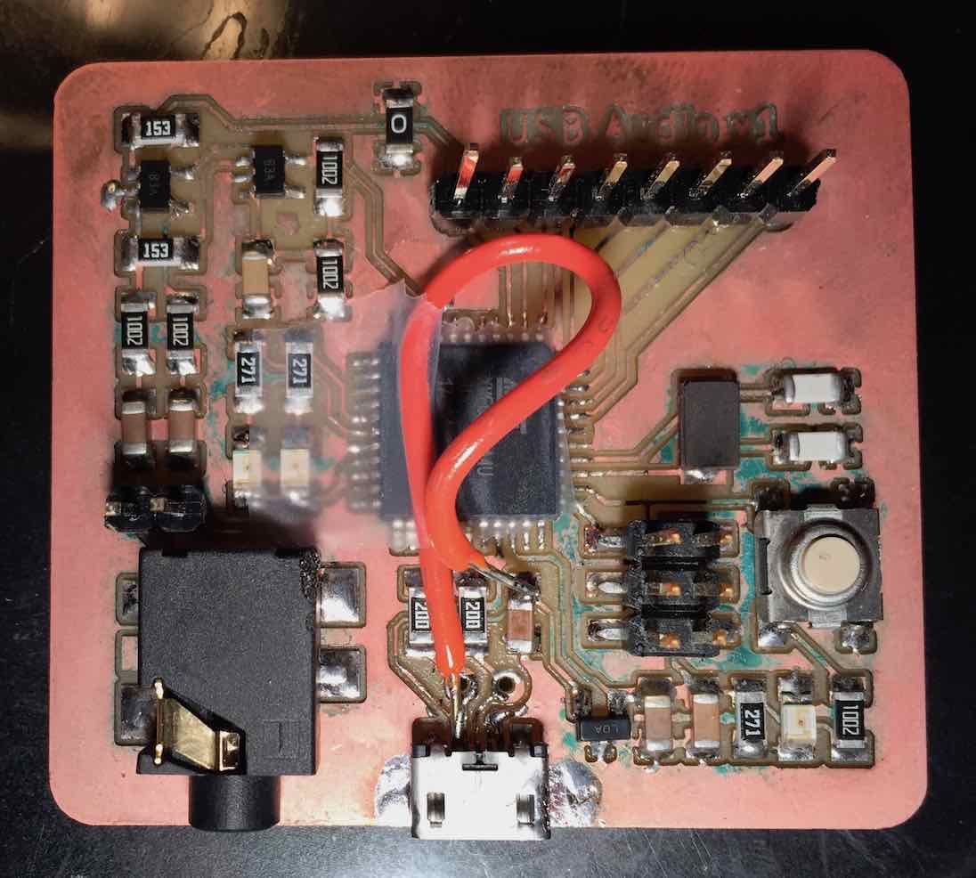
I think I got most of the leads reconnected, though in the image above the power jumper has some really ugly (and maybe cold) joints. Eventually I decided I should save myself the frustration of working with a damaged board. Especially since I learned of a few things I could have done better.
Back to the Drawing Board
Or back to board drawing, as it were. Anyway, I wanted to make a few changes before milling again:
- Add additional bypass capacitors near all the XMEGA’s power pins
- Get rid of the 22 ohm resistors (unlike the ATmegas, the ATxmegas have these internally)
- Switch to a single-ended op-amp configuration
- Add mounting holes and pads for an external audio jack and volume knob
The first is just good practice for microcontrollers. I added 0.1uF caps near all the XMEGA’s power pins, and a few 10uF caps near potentially large current sinks (i.e. LEDs and op-amps). I had added the 22ohm resistors because all the examples I looked at had them. But after going through the XMEGA’s datasheet in more detail, I found that it has an “integrated on-chip USB transceiver, no external components needed”. I wanted to go to a single-ended op-amp configuration to make it simpler to add a potentiometer to control gain. With my current differential setup, I would have to use a double-ganged pot, and if the two resistances didn’t stay exactly the same at all times there’d be additional error in my output. So I’ll just connect one side of the input to ground, and send the other through an AC-coupled non-inverting amplifier with a DC bias. Finally, the gain control knob and audio jack will be better off mounted to the chassis of the device rather than the board, so that the board doesn’t bear any unnecessary mechanical load. It would be nice to attach the USB jack to the chassis as well, but the USB jacks we have in stock are surface mount, and since it’s good to keep the data leads as short as possible, I’ll leave it on the board.

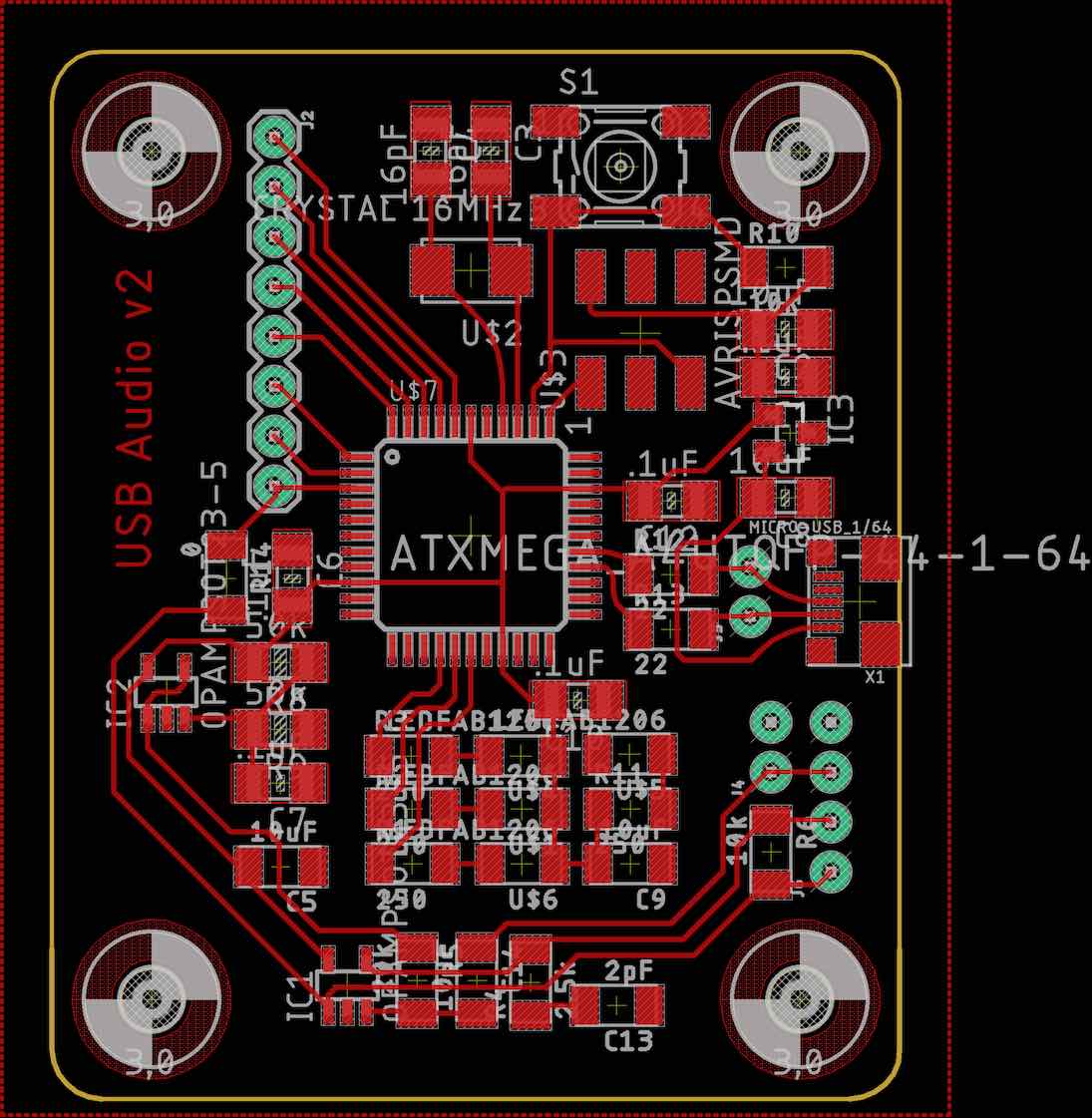
If I lay this out a third time, I’ll make more careful use of the grid. I could also move the LEDS to the left of the XMEGA, and connect the audio signal to a pin on its bottom side, to shorten my critical analog traces. Speaking of which, I could have a separate analog ground plane and voltage rail. But this will definitely work for now.
More Milling
I hoped that the ripped leads on my first board were a fluke, so I milled the second one just like the first. But the same thing happened, in the exact same place.
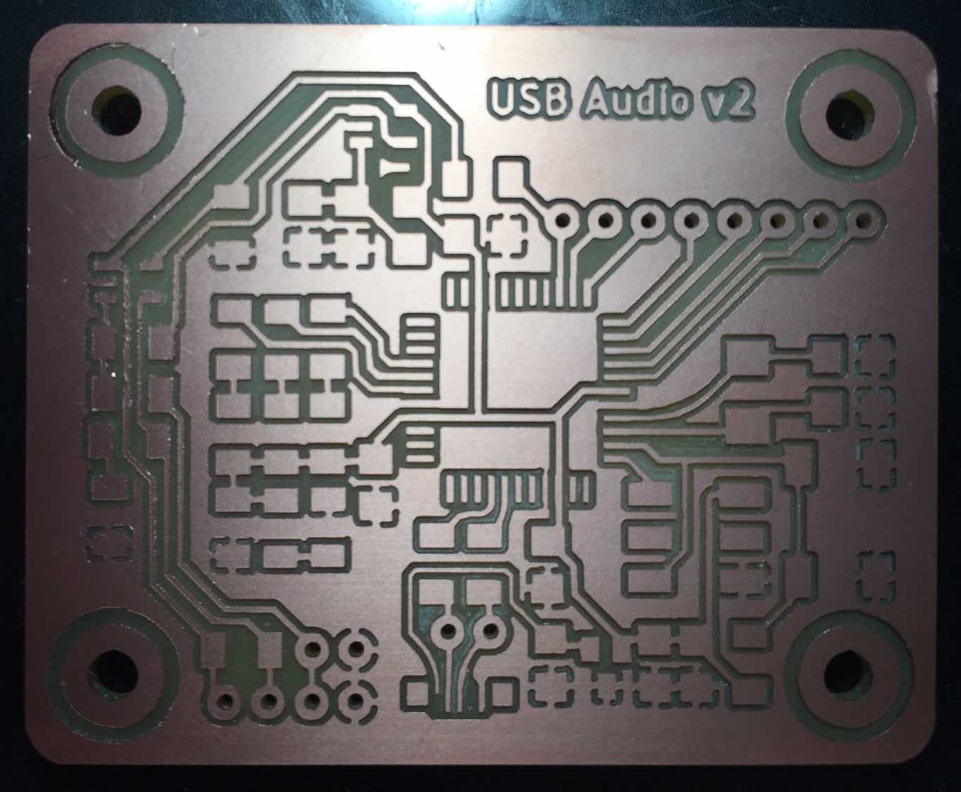
Rather than deal with jumpers again, I thought I’d fix the manufacturing. So I grabbed a 0.01” endmill to use just for the USB pads.

This time I cleaned the whole board with isopropyl alcohol (70%) to remove leftover flux and prevent early oxidation.
Software (Second Attempt)
To begin I’d like to make my board become a USB virtual serial device, since this is probably the simplest example that LUFA has, and I already have my own C++ to listen to serial devices. (Side note: I wasn’t sure my code would work with USB virtual serial devices, but Linux presents these devices as device files in /dev just like the FTDI device I used before. So though different drivers are being invoked under the hood, at the level of libserialport they look the same.)
Though the LUFA code looked quite daunting at first, I only needed to change a few things to get it to run on my board. First, I commented out everything referencing code from LEDS.h and Joystick.h, since I don’t want to create these files for my board (and I don’t even have a joystick). Instead of reading a value from a joystick, I’ll just spam “hello world” all the time. In the Makefile, I set ARCH to XMEGA, and the clock rate to 48MHz.
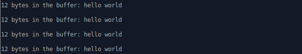
After programming, my serial port code detects a new device: /dev/ttyACM0. When I open the port, I get see a constant stream of “hello world” as expected.
Since this week is ultimately about networks with addresses, let’s try to find the address that my board is assigned by my computer. I grepped for “address” in LUFA and after following a few function calls found my way to LUFA/Drivers/USB/Core/XMEGA/Device_XMEGA.h. At line 217 LUFA is writing the newly assigned address to one of the XMEGA’s registers.
static inline void USB_Device_EnableDeviceAddress(const uint8_t Address)
{
USB.ADDR = Address;
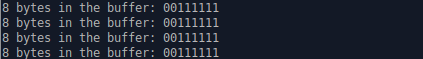
}Instead of spamming hello world, I can read back this register and make my board output its own address.