Week 4: Electronics Design
Introduction
This week, I learned how to use the 3D printer as a way to transform a 3D digital file to a physical object, and I learned how to use a 3D scanner as a way to transform a physical object to a 3D digital file.
- Software used: Eagle, Photoshop, Avrdude
Designing the board on Eagle
I was recommended to use Eagle over KiCad, a decision that I am pretty happy with. Students get Eagle for 3 years for free. To properly be able to design PCBs in Eagle for this class, we needed to have the fab and supply1 modules. I’ll refer to Dan Chen’s Guide for more details on how to do this assignment.
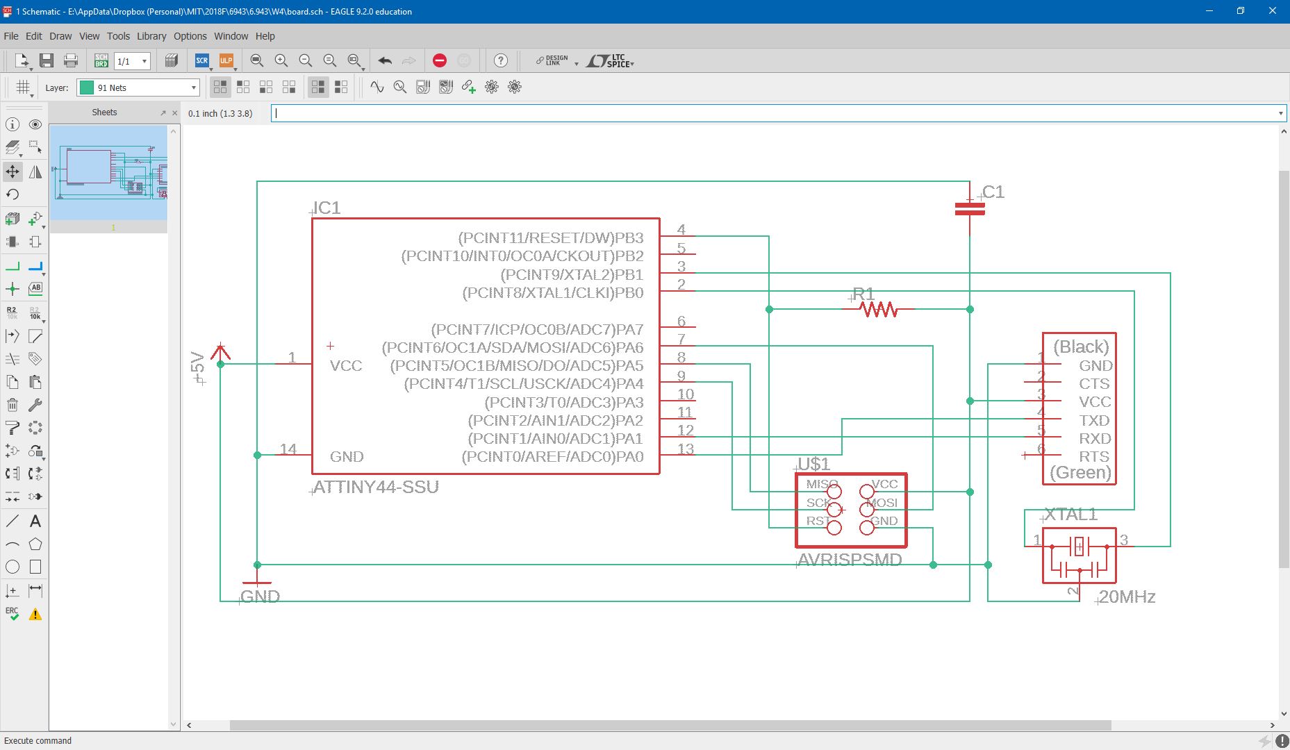
I first designed the schematic without the LED and button:
…and then I added the led and button (with a resistor between the two and ground)
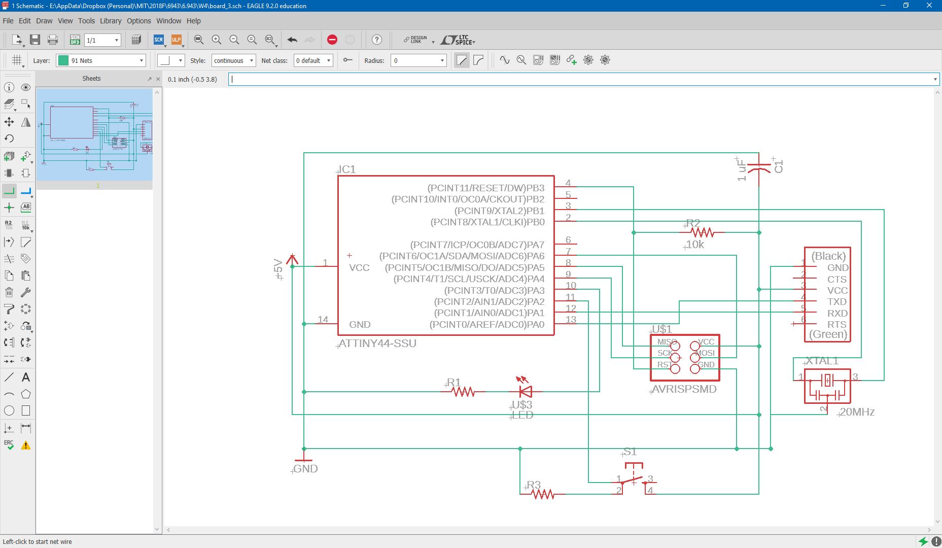
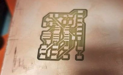
Designing the board schematic was a rather frustrating process. We run autorouter to have the program figure out the best routes for milling. It is important to add design rules to make sure the routes aren’t too narrow or too close to each other -otherwise your mill will turn out something like my first:
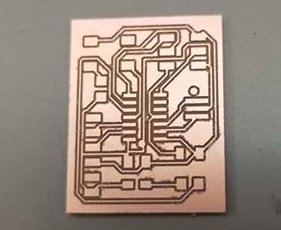
However, after some time I was able to get the board design properly as follows:
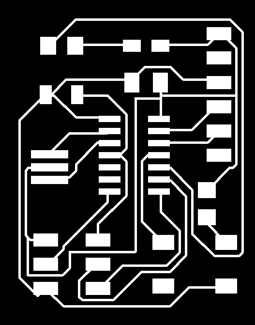
Dimensions are important to keep track of, so I exported the board schematic as a 500dpi image, under a monochrome setting. I added a border in photoshop (paint will also suffice). Here is the file for my trace and outline.
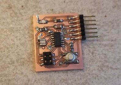
I used the Tiny Mill this time to mill my board, which turned out as follows.
Next, I stuffed the board:
And I was ready to program the board.
Programming the board.
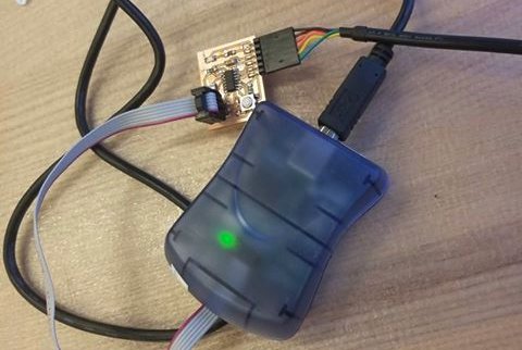
The programming for this week is similar to what we did in week 2. First, I connected the programmer to my board and also connected a power supply to my board as follows:
Assuming that avrdude and the software from week 2 has been configured properly, we essentially follow the instructions in this image
To summarize:
- First download hello.ftdi.44.echo.c and hello.ftdi.44.echo.c.make.
- Run
sudo make -f hello.ftdi.44.echo.c.make program-avrisp2-fuses - Run
sudo make -f hello.ftdi.44.echo.c.make program-avrisp2- Keep in mind that if you are not using the avrisp2 programmer (the blue box), you will need to replace that text with whichever programming device you are using according to Brian
- Run
sudo python term.py /dev/ttyUSB0 115200
It’s finally working!
Tips for the future
- Design rules for Eagle are very important!
- To solder fast, I ended up over-adding material and then stripping the extra solder material. This turned out to be faster than last time… I am still experimenting.
Assignments
- Design and mill a PCB board for the Hello World Program
- Program the board