electronics production
This week, we made the FabTinyISP, which is an in-circuit programmer that we will use later on in the class. I followed the instructions outlined here.
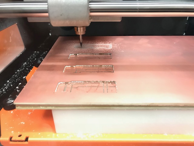
This is the Roland SRM-20 milling the board.

These are the traces. They were milled with a 1/64" end mill. Below is the cut shape, which was milled with a 1/32" end mill.

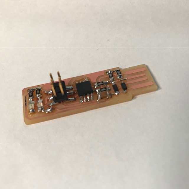
The traces were milled, which was a very neat and fast process (traces+cutting the board took under ten minutes, I think). Then I soldered everything on, which was a less neat and fast process. I initially grabbed all the wrong resistors (I thought the labels were for the box above and not the box below, so everything was like an order of magnitude off, oops), so I had to re-do those. But now the programmer works, I think? The programmer's a little ugly, but I'd like to think that just means it has character.
I'm looking forward to using it; I don't have very much EE experience, so this stuff is pretty exciting for me.
Can confirm, the programmer works. Tested it on electronics design week. I had a dumb moment where I thought it wasn't working because I plugged the programmer in and the lights didn't turn on. And then later it hit me that there's no LED between VCC and GND, so nothing is going to light up just because the board is recieving power. Anyways, the red LED will turn on brightly when plugged into a recognizable target board, and it will turn on very dimly when plugged in backwards, and that's how you can figure out ISP cable orientation.
Another note, you do have to build up the USB pads a bit with solder, but certainly not to the capacity I did with this board. If the board doesn't fit well in a USB port, the thing to do is add thickness under the board (which I do with layers of tape).
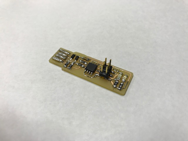
I also remade this board. Pictured below, sans solder layer on the USB traces.