electronics design
The individual assignment for this week was to remake this echo hello world board but with an LED and a button added. I made the schematic and board layout in Eagle. At first, I was visually connecting all of the components, but when I looked through some of last year's pages, I noted that some people made most/all of the connections just by naming nets, which resulted in a much less jumbled visual workspace. To that end, it's also nice to connect nets using power symbols, which I found in SparkFun's Eagle libraries, a little later.
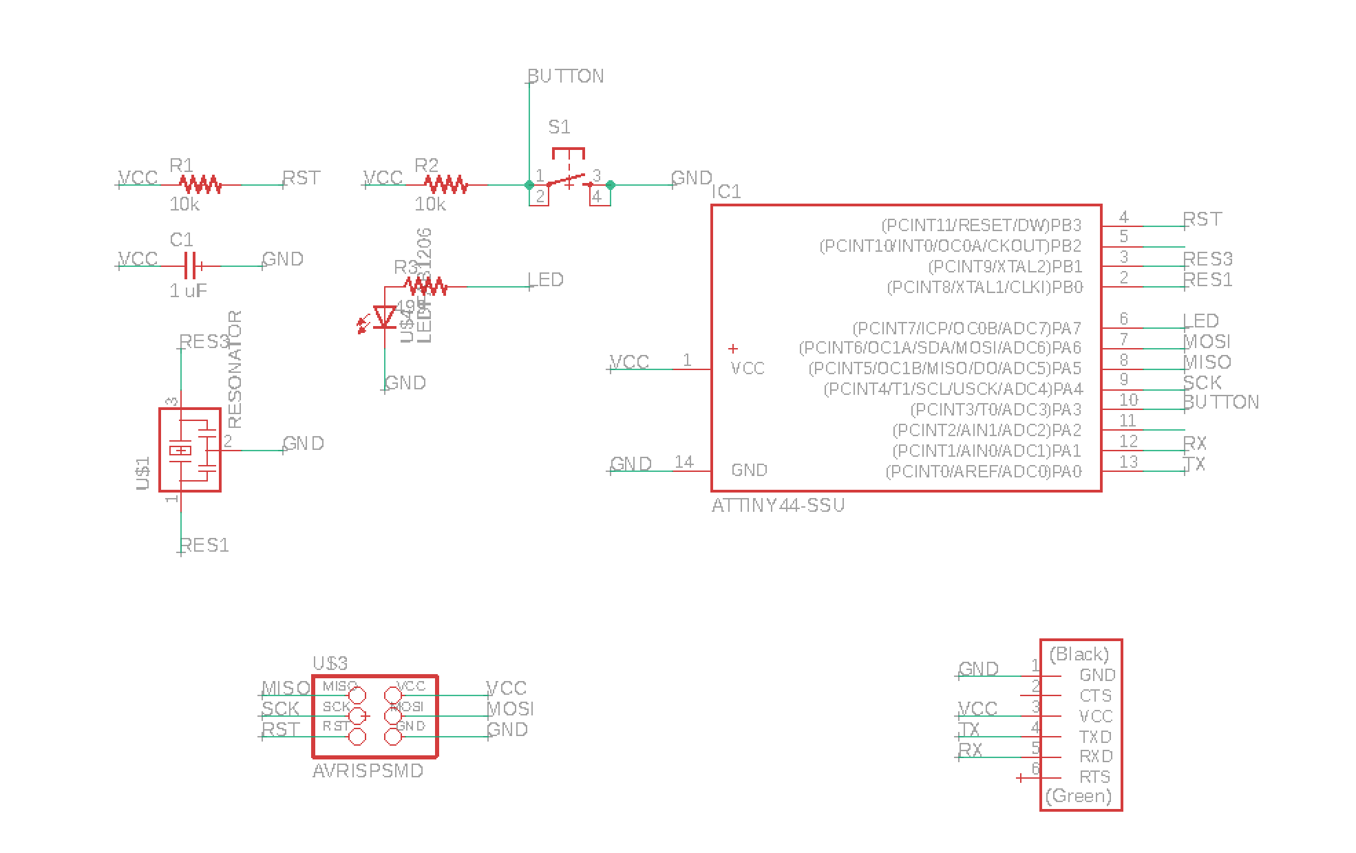
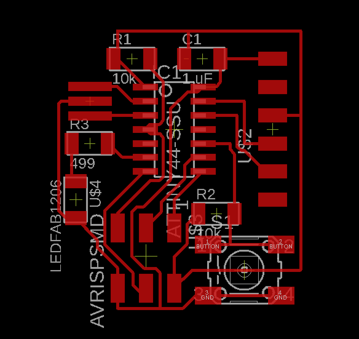
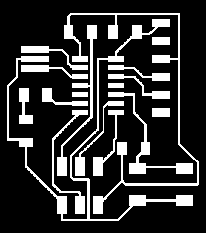
These are some screenshots of my Board and Schematic layouts. I used this guide. There are two extra LEDs in this design. The LED current limiting resistor is at 499 ohms and the VCC/button resistor is at 10k ohms.
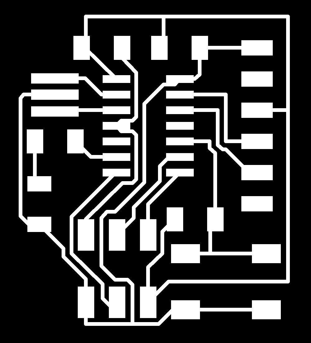
Also the PNG image I used for milling! A good thing to note: make sure your outline and trace images are the same size, or at least aligned along the lower-left corner, so that the milling machine picks the same relative origin for both. I initially made the outline a larger file, and then realized that wasn't going to work when the person using the machine before me made the same mistake. So yay for learning from others?
Using Eagle was relatively straight forward, though not without issues. I didn't find autoroute to be particularly useful, and it took me awhile to figure out a routing pattern that didn't have any collisions/other issues. An unfortunate part of the Eagle interface for me was that I didn't realize that the routes weren't necessarily going to a component unless you clicked directly in the center of the component, so I had an amount of surprise air wires that I had to deal with. These are relatively easy to find though; I just turned off all the layers but air wires to find them, and re-routed the corresponding sections.
After cutting the board, I realized that I'd assumed all of the settings in the provided design rules were accurate to the EECS section mill, but the necessary clearance around other parts was too low, so when I actually milled the board (with a Roland SRM-20), a lot of the pads and traces had merged together. That board is kind of a mess, and I need to re-mill it with the fixed design rules. I tried manually fixing it (i.e. cutting traces off with an exacto, but this is not a particularly effective strategy for delicate features). I'm not actually sure why the clearances were too low, because the min. distance was set to 16 mils, which is greater than 1/64", but maybe the mill adds in tolerances that bump the 0.0156 up to 0.016? Luckily, though, I'd milled another of the same circuit with a different board layout!
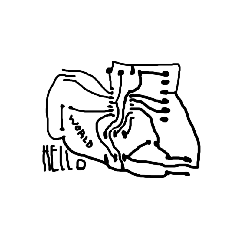
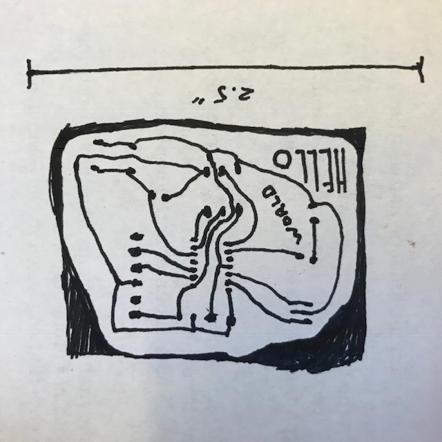
I thought the hand-drawn board from a previous year looked very cool (link here), so I tried my own version of that. It's the exact same circuit as the other one, but hand drawn (which basically introduces a physical set of design rule: thickness of ink line, shakiness of hand, etc.). I drew the board at-size, based on the actual physical components (this isn't actually very difficult; you can immediately check if your traces fit the part or not). I then scanned it in, messed around with it in photoshop until it was a black and white smooth image, and cut it out. Most of the traces/lines/etc. in this board turned out fine, and the dimensions fit all the parts.
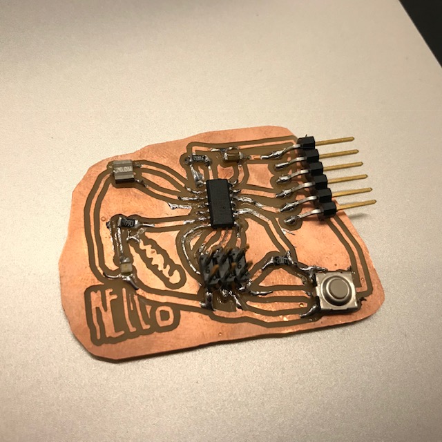
Testing the board for shorts and the expected voltages (which I could be totally wrong about) was good (I don't know how to phrase that. Point is, nothing was not-working so far as I could tell). But, I haven't had time to test the board yet. And then I accidentally put some heavy groceries on top of the board and maybe it got smushed a little :O
I haven't quite finished up this assignment yet, but I will soon. Still to do are: program the hand drawn board and re-mill + make the standard Eagle board.
Alright, so I programmed the board with Neil's Hello World Echo Program. AND IT WORKS, omg. I can't get Neil's term.py to run on my computer though (but it works fine on the linux machine at the EECS shop). I initially thought it was a python 2.7 vs python 3.[3?] issue, but it doesn't run on my computer in either of those situations :(.
Neil's code: c program, makefile.
The makefile generates a hex file out the c program, and tells your programmer important info about the target board (e.g. what it is, and what is clock speed is). On a mac with avr dude, the way you run this stuff is:
- navigate your way to the right directory (~$ cd [directory])
- tip tap ~$ make
- that'll make the files you want, and then you want to ~$ make program-usbtiny (or other thing for whatever your programmer is)(and then it should work).
I also re-milled/re-drew this board a few more times until I got a working one made from Eagle (i.e. the reasonable workflow). If you look at input devices week, you can find another board I made and accidentally destroyed and then more intentionally destroyed.
Above are the traces to a board that actually worked. Something to note is that the blue LEDs will not turn on with 499ohms, while the red and green ones will.
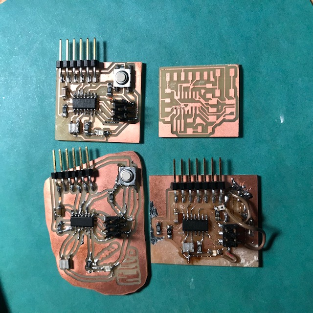
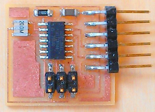
these are all the boards/sort of boards I made for this week.