Assignment: Read a microcontroller data sheet, and program your board from Week 5 to do something, with as many different programming languages and programming environments as possible.
Goal: Program my board using the Arduino IDE, as well as via CrossPack and AVRDUDE from the command line.
Throughout my weekly projects in this course, I've been thinking in the back of my mind about how I would teach these technologies and processes to high school students where I work. One thing I really wanted to try was programming my board using an Arudino Uno I had on hand; it seemed like an easier entry point for a student learning embedded programming than going through the process of setting up their own FabTinyISP to start. As such, I had a couple of objectives for this week. I wanted to try programming my board both with my FabTinyISP from Week III and with an Arduino Uno I had on hand.
Arduino Uno as ISP
I was still having trouble getting my FabTinyISP to work on my Mac, so I figured I'd get started by programming my board with my Arudino Uno. I had no idea where to start, though thankfully this process is verywelldocumentedallovertheweb. I figure the original documentation came from this High-Low Tech article, though I also needed this other High-Low Tech article to complete the process. Regardless, the process is relatively straightforward once you know what to do.
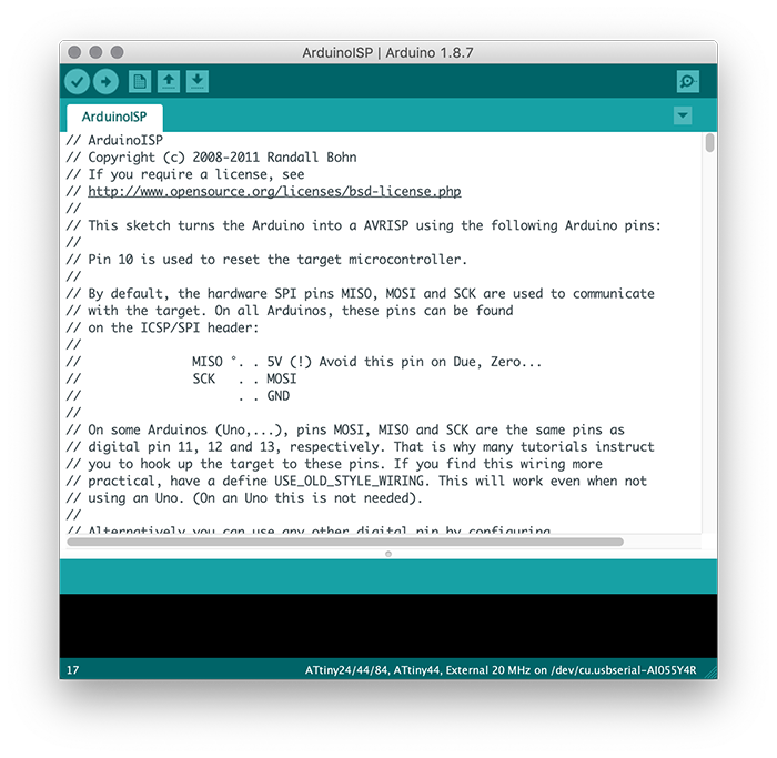
With the board connected to the computer, go to File > Examples > ArduinoISP, and upload this sketch to the Arduino.
Step 3: Install support for ATTiny in the Arduino IDE
Go to Preferences > Additional Boards Manager URLs and paste https://raw.githubusercontent.com/damellis/attiny/ide-1.6.x-boards-manager/package_damellis_attiny_index.json. Then go to Tools > Board > Boards Manager, scroll to the bottom of the list, and click the install button by the ATTiny entry. The ATTiny microcontrollers will now show up at the bottom of the Board menu.
Step 4: Open (or create) a Sketch to load
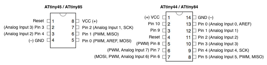
You can program the ATTiny just as you would any other Arduino board, including using pinMode(), digitalWrite(), delay(), and other standard Arduio functions (see here for the full list). The pin mappings are displayed below; note that the pin mappings are different from the actual pin numbers on the board. This point tripped me up while I was programming.
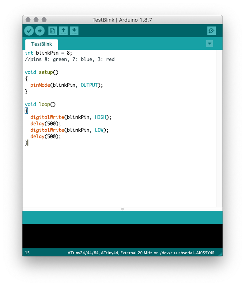
This was the code I used, based on the basic blinking LED example:
Step 5: Set the ATTiny processor and programmer
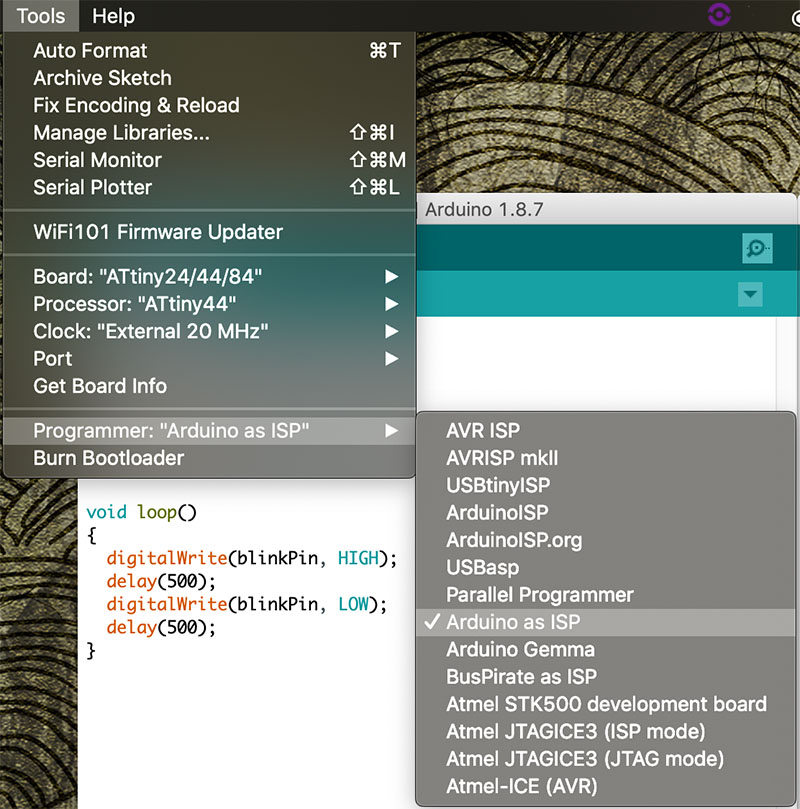
In the Tools menu, choose the corresponding Board, Processor, and Clock for your project. Then choose the Arduino as ISP option from the Programmer sub-menu.
Here's my setup:
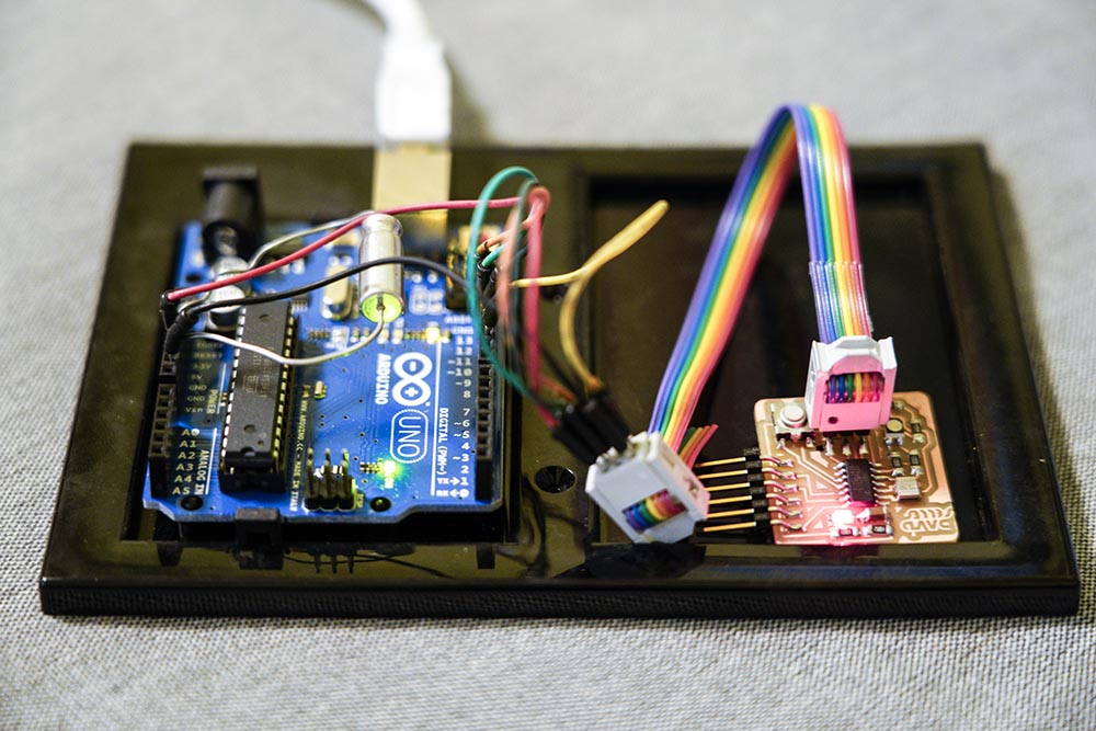
Step 6: Connect the things
This step depends on your particular setup, but the ArduinoISP example sketch lists which pins on the Arduino should be connected to MISO, MOSI, and SCK. Pin 10 on the Arduino would go to the RESET pin on the ATTiny. You can see any of the resources I linked to above for examples of this. Note that the High-Low Tech article recommended a 10uF capacitor between RESET and GND on the Arduino.
Step 7: Burn bootloader and upload sketch!
With menu options set and electronics connected, it's time to burn the bootloader. Just go to Tools > Burn Bootloader, and then upload your sketch.
After going through this process, I had my board blinking in no time. Turns out it's super bright - I knew I would be pushing the RGB LED to the high end of its recommended operating conditions, but I didn't realize it would be quite so bright. Good to know for future reference.
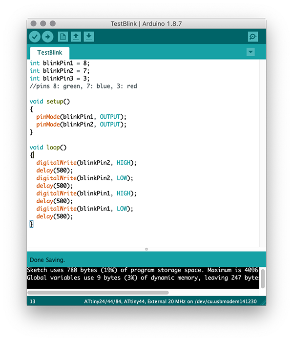
However, programming the board in this manner is resulting in some unexpected behaviors. For instance, see the following code, and the following result:
Instead of green-off-blue-off it goes green-cyan-blue-cyan. Or perhaps cyan-green-cyan-blue. Seems like the code is able to turn one LED off at a time, but not both at the same time, which I'm guessing is an error with the bit logic in the back end (or user error on my part). Regardless, I wanted to try programming my board at a lower level than using the Arudino libraries.
Programming with the FabTinyISP
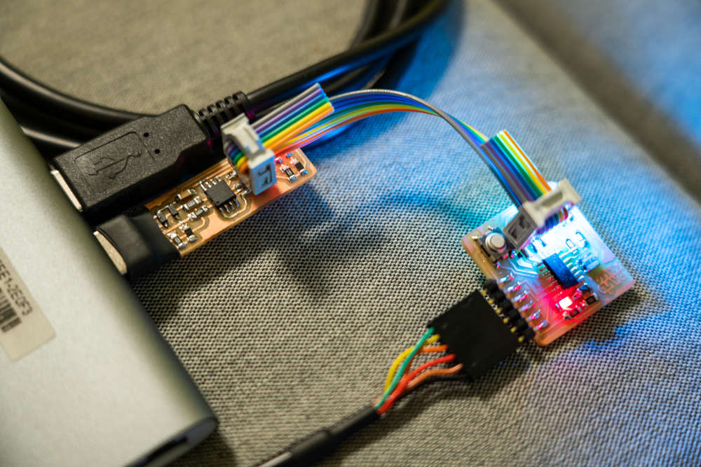
Programming with the FabTinyISP I made in Week III was pretty easy using the Arduino IDE. All I had to do was swap out the programmer from Arduino as ISP to USBtinyISP in the Tools > Programmer menu. Everything worked almost as expected, though I found my FabTinyISP wasn't able to supply power to my board. I think this is by design; with this setup the board is intended to be powered via the FTDI cable, even though the Arduino Uno was able to supply power to my board through the ISP header alone.
Admittedly, this setup is quite a bit more convenient than the mess of wires when using the Arudino Uno as my ISP.
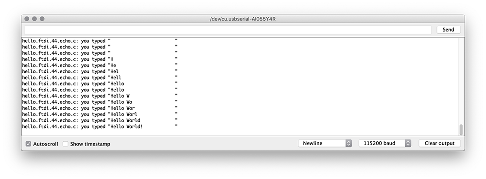
From here, I wanted to break out of the Arduino IDE to program my board with Neil's Hello-World test code. However, AVRDUDE wasn't able to find my programmer via the command line (though it did work in the Arduino IDE). Brian Mayton (the same Brian behind the FabTinyUSB design) pointed me in the right direction. Turns out the AVRDUDE included in CrossPack doesn't work with the newer USB-C ports on my Macbook Pro. All it took was a simple re-install of AVRDUDE using Homebrew: brew install avrdude --with-usb. Additionally, I keep forgetting the syntax for uploading code to the board using AVRDUDE. I'm including it here for reference: make -f hello.ftdi.44.echo.c.make program-usbtiny. That is, make -f filename program-programmer.
The Arduino IDE has a nice serial monitor which I used to interact with the board. After some trial-and-error, I was able to get it working after I installed the driver for the FTDI cable and subsequently restarted my machine with the cable plugged-in. It then showed up in the Port list in the Arduino IDE. Note the baud rate of 115200, as per Neil's code.
Getting Cozy with C
Rob Hart's Tutorials were super helpful to get me started, along with this primer on C's data types and this overview of registers. Page 50 of Elliot William's Make: AVR Programming does a nice job of going over the PORTx (applying voltage/pull-ups to pins), DDRx (setting pins as inputs vs. outputs), and PINx (reading states of input pins) registers. With these in hand I was able to code a simple program which turns on all colors of my RGB LED at once when the button is pressed. I've linked to my code at the top of this page. Note that you'll need both C and MAKE files to compile the program.