
Week 4: Designing Circuit Boards
The Task
In week 4, we were tasked with copying the “hello world” board and adding some basic things to it (LED, button).
Eagle
I wonder why Eagle is called Eagle. When I think of eagles, I think big majestic birds. When I think Autodesk Eagle, I think of the original pain and suffering that I underwent learning how to design printed circuit boards using it.
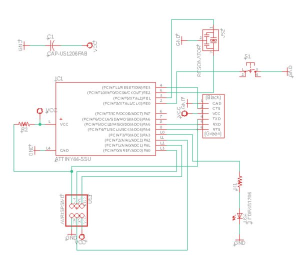
Making a board starts with making a schematic, which fully describes the circuit’s logic. What I didn’t understand was why the schematic for the ATTiny45 had all 14 paths on one side - in reality, there are 7 paths on each side. I also didn’t realize that there is a set mapping from the numbers of the paths to physical location when a board is rendered. This combined with me trying to do the entire schematic on my own without clearly following Professor Gershenfeld’s nice board image meant that I was utterly lost. I spent about 3 hours hopelessly trying to draw routes after finishing my schematic. Below is my bad schematic. For sake of not confusing anyone who will try to route in the future, I will omit images of my terribly routes.
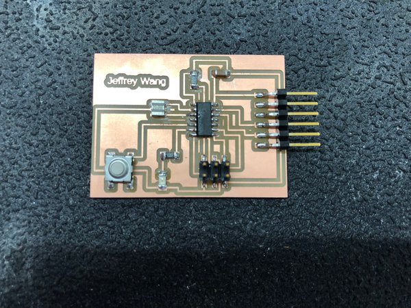
Eventually, I decided to cave and and follow Neil’s schematics. Below is my final schematic and my final board.
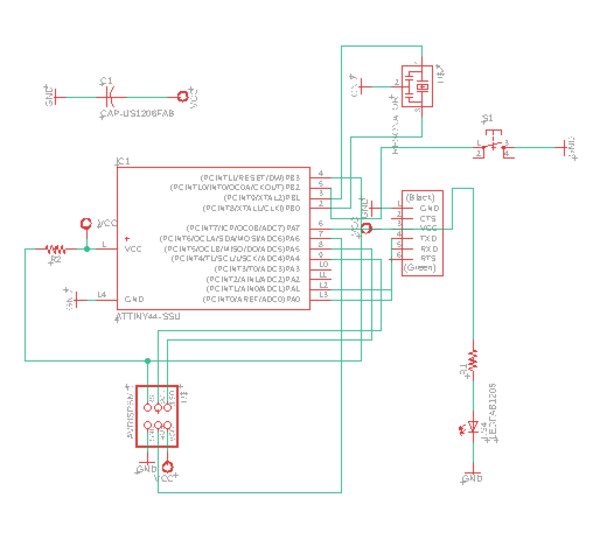
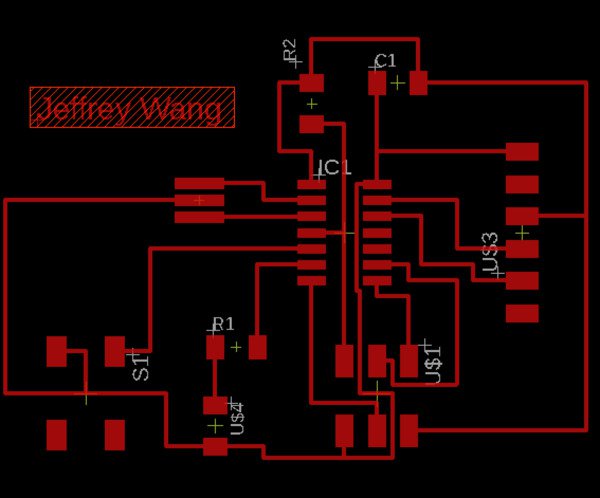
As you can see, I decided to do the minimum this week, which is putting one LED and one button on top of the stock hello world board. In the next week, I hope to make some boards that do more than this, but for now, I think that this will suffice.
Some final tips for using Eagle:
- If you decide to make the PNGs for trace and outline using Eagle’s export function and you are using a Mac with a Retina display, be sure to double the resolution when using mods.
- Further, when you export, use monochrome setting and choose “full” and not “window” for the area that you want to make your PNG with. Otherwise, there will be a lack of standardization between the trace and the outline.
Making the board
After spending so many hours milling two weeks ago, I thought that I would be an expert and get things to work on the first try. Alas, behold my graveyard of failed milling attempts:
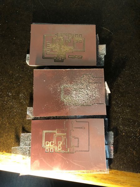
The errors that I had all relate to my failure to export from Eagle properly.
After exporting from Eagle properly, I finally milled a good board:
The next step was soldering. I gathered the components from SC102 and soldered just like last week. To learn from my mistakes from that week, see Week 2.
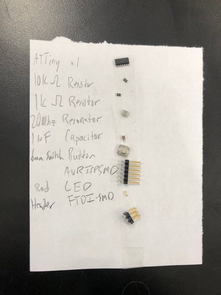
Here are the components and the final board:
Programming
Programming the board involves a few C files and one Python file. The C files are given with the assignment,
but the Python file term.py is found in the embedded programming unit site. I used the Linux desktop in SC102
to load the programs. I ran three commands that all worked:
make -f hello.ftdi.44.echo.c.makesudo make -f hello.ftdi.44.echo.c.make program-usbtiny-fusessudo make -f hello.ftdi.44.echo.c.make program-usbtiny
All of these commands ran with 100% success. The next command was running the Python script, and for some reason, it did not work - I was unable to type anything into the graphical interface. Currently, I’m in debugging mode - I tried replacing the controller in case it was fried and also resoldering many components but have not been successful. I will post updates when I have them.
Update: It turns out that my board was working fine - I just needed to use the
Arduino IDE to send input characters instead of term.py, which was freezing on
me for some reason. Highly suggest doing that instead of using term.py. Use
Arduino IDE by going to the “Serial Monitor” in the top right corner. However, I
had to go through the ordeal of making 3 boards to figure this out.