
Week 8: Input Devices
The Task
Measure something. Add a sensor to a microcontroller board that you have designed and read it.
My Idea
Ideally, I would have used this week to test out my GPS module for my final project. Alas, it is still shipping. I decided to do something that would have similar code and that would also be useful to me. I decided on making a thermostat that emails me the temperature every 10 minutes. This is particularly useful to me because the temperature in my room is always changing because I have the windows constantly open because of my mining rig.
I decided that email would be better than a web server because I currently just don’t have any web servers running for any personal sites or anything of that sort.
Design
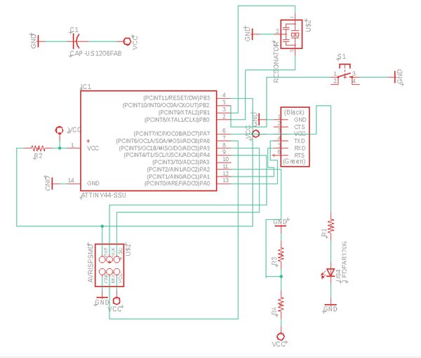
I based my board off of the board that I made two weeks ago. I simply added a negative temperature coefficient (NTC) thermistor.
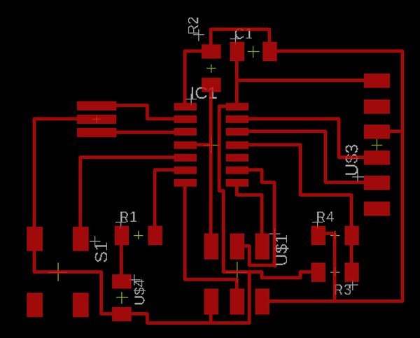
One thing that I changed is making the board a lot more compact. This is in alignment with my final project, for which I want to create as small of a board as possible.
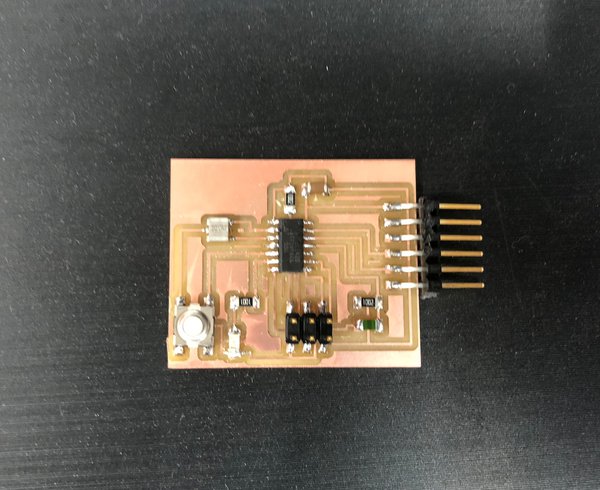
Milling this week was pretty straightforward, as was soldering. I got things on the first try, which was super nice.
Loading my code from two weeks ago showed that the board was sound - the coin flipping aspect worked.
Programming
The next step was programming to see if my sensor actually worked. For this week, I wrote two programs. One is the Arduino program that dictates the actual behavior of the board. My board works as following: the button is an on/off switch. When the board is on, the LED is lit and the board spams serial port 9600 with the voltage that is measured between the two resistors.
For a little background about how NTC resistors work, my understanding is that they are resistors whose resistance depends on temperature (higher temperature, higher resistance). In combination with another resistor, physical laws including the Steinhart-Hart equation allow one to calculate the actual temperature from the voltage reading (which gets you the resistance).
Arduino
I started by seeing if I could do some basic serial output. I actually had tons of trouble with this.
Firstly, if you use ATTiny44, it is necessary to include
a header file called
Secondly, once I got serial outputs to work successfully, I was getting nonsense outputs from the serial interface in the Arduino IDE in the form of reverse question marks. After being super confused for a long time, I pondered upon another weird problem that I was having - the clock cycles seemed to be very slow. Connecting the dots, I realized that the nonsense output was the result of baud rate not being set well. In previous iterations of board, I had always loaded test C programs before doing anything with Arduino. But with this board, I tried to do Arduino coding first. The result was that I never set the fuses on the baord. Using the “burn bootloader” Arduino command set things right, and then my serial output started coming out properly.
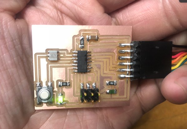
Finally, I initially got voltage readings of 0 from the pin for the thermistor. Thankfully, Rob helped me debug this one - one of my traces underneath my FTDI header was not connected - it had probably come off during soldering or something. Rob helped me to use a piece of copper wire to connect the traces. After this process, the voltage read correctly and we were good to go!
My code is the following:
#include <SoftwareSerial.h>
/*
  Temperature Emailer
  Jeffrey Wang, 10/23/2018
 */

const int ledPin = 7;
const int buttonPin = 8;
const int thermPin = 2;
const int rxPin = 0;
const int txPin = 1;

SoftwareSerial myserial(rxPin, txPin);

// the setup routine runs once when you press reset:
void setup() {
  pinMode(ledPin, OUTPUT);
  pinMode(buttonPin, INPUT_PULLUP);
  pinMode(rxPin, INPUT);
  pinMode(txPin, OUTPUT);
  myserial.begin(9600);
}

bool on = false;
bool was_pressed = false;
unsigned long last_press_time = 0;

// the loop routine runs over and over again forever:
void loop() {
  // button is not pressed
  if (digitalRead(buttonPin) > 0){
    if (last_press_time != 0 && millis() - last_press_time < 0.5 * 1000 && was_pressed) {
      on = !on;
      was_pressed = false;
      if (on) {
        digitalWrite(ledPin, HIGH);
      } else {
        digitalWrite(ledPin, LOW);
      }
    }
  }
  else {
    if (!was_pressed){
      last_press_time = millis();
    }
    was_pressed = true;
  }
  if (on) {
    int reading;
    reading = analogRead(thermPin);
    myserial.println(reading);
    delay(50);
  }
}
Python
Now that I was successfully receiving voltage readings from the board, I sought to write the Python code that reads these voltages, converts them into temperatures, and then sends emails every 10 minutes.
The emailing part was made pretty easy because of a native Python library
called smtplib. Some basic reading about the library proved that it was pretty
straightforward.
The serial reading was also pretty straightforward with the use of the pyserial
library. Serial can be read line by line. I store up to 20 voltage readings
in a queue - every 10 minutes, these readings are averaged and a temperature
is emailed.
My code was the following:
import smtplib
import serial
import time
import sys
from collections import deque
import math

num_samples = 20
# look at datasheet of thermistor to find this number
b_coeff = 3750
series_res = 10000
temperature_nominal = 25

# some magic physics
def v_to_t(v):
    r = series_res / (1023 / v - 1)
    r = math.log(r / series_res) / b_coeff + 1 / (temperature_nominal + 273.15)
    r = ((1/r) - 273.15)*9/5 + 32
    return int(r)

server = smtplib.SMTP('smtp.gmail.com', 587)
server.ehlo()
server.starttls()
server.login('roomtemp128@gmail.com', 'noneofyourbeeswax')
port = sys.argv[1]
ser = serial.Serial(port, 9600)

last_time = None
temp_queue = deque(maxlen=num_samples)

while True:
    temp = int(ser.readline())
    temp_queue.append(temp)
    current_time = time.time()
    if (last_time == None or current_time - last_time > 10 * 60):
        print("got it")
        last_time = current_time
        msg = "\n" + str(v_to_t(sum(temp_queue) / len(temp_queue))) + ' degrees Fahrenheit'
        print("msg: " + msg)
        server.sendmail('roomtemp128@gmail.com', 'roomtemp128@gmail.com', msg)
Note that the magic physics was explained by Lady Ada in this super helpful post.
I got super lucky this week and after the intiial bugginess with serial stuff, temperature was reported quite smoothly.
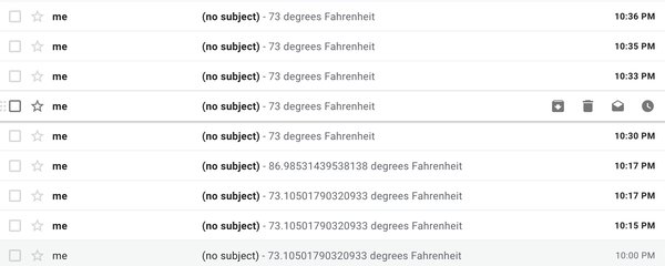
Note that the reading of 86.98F was when I pressed my thumb against the thermistor before reading.
The next step is to create an FTDI cable so that I can actually use this in my room.