
Week 9: Output Devices
The Task
Add an output device to a board and do something.
My Idea
I finally got my GPS modules for my final project, so for this week, I want to start building. my plan is to build that and then have some output that is based on the GPS data that is being recorded. To this end, it would be cool to have an LCD display some GPS metrics. My individual project for this week is thus to do just an LCD board.
Design
I based my board off of Neil’s LCD board - all his stuff can be found here. I added a switch so that I can perform some logic using the board. Later, I hope to replace the ATTiny44 with an ATMega328P because my final project will probably require code that takes up more space than the ATTIny44 has.
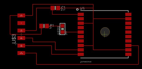
Below is the Eagle schematic and board.
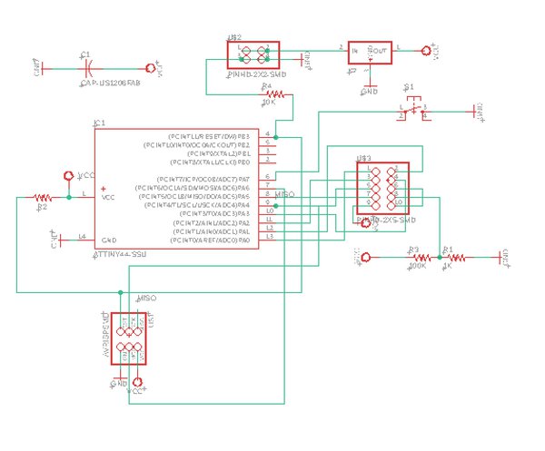
One thing that I had trouble with this week is finding the necessary components because Neil’s page doesn’t make clear what components are necessary. The components are as following:
- 0.1µF capacitor
- 100K resistor
- 10K resistor
- 1K resistor
- 2x3 header (find in fab library, called PINHD–2x3-SMD)
- 2x2 header (find in fab library, called PINHD-2x2-SMD)
- 2x5 header (find in fab library, called PINHD-2x5-SMD)
- ATTiny44
- 5V voltage regulator (smaller one called REGULATORSOT23)
Milling and Soldering
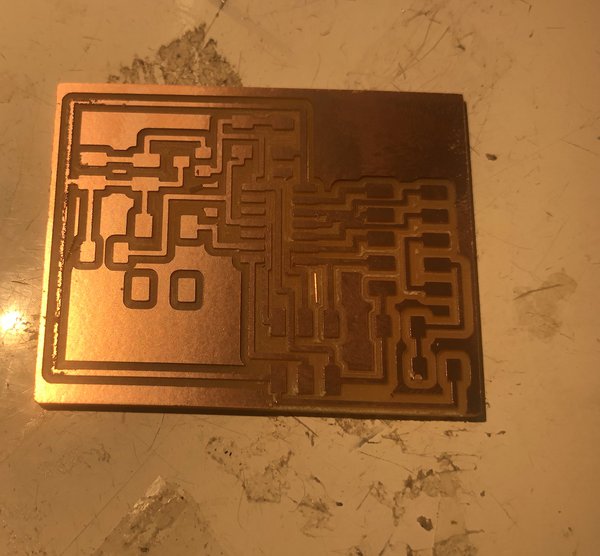
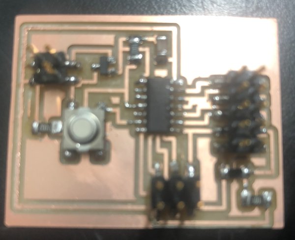
Milling and soldering went super smoothly this week. Here are my milled and soldered boards.
Post-Work
Powering Device
Because there is no FTDI header on this design, power comes from the 2x2 pins. I asked Rob how to power the board and he gave me the advice to use a 9V battery with ribbon headers.
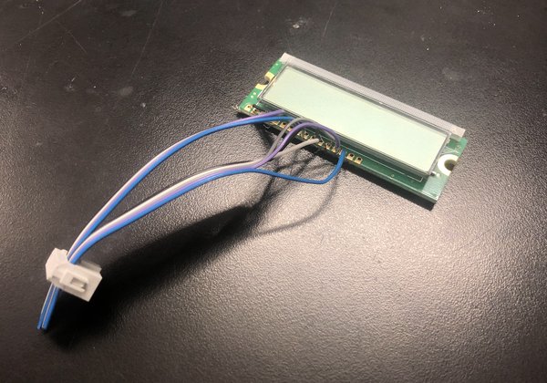
Further, the LCD is connected using a 2x5 header that I made. Each of the 10 wires I stripped using a wire stripper. Then, I soldered each wire to pins on the LCD according to the datasheet of the LCD.
Pins: 1,2,3 - power pins 4 - high means data is characters, low means data is instructions 5 - Read/Write (high is read, low is write) 6 - Enable 7-14 - data 15/16 - no connection
Below is the finished LCD module soldered with wires
DISASTER: After all these steps, I am at a point where everything seems to work but there is soething very sketchy going on - when I plug the power in, whether it’s from a battery or from pins of an FTDI cable, the power source becomes extremely hot extremely quickly. This is really troubling, and I want to ask about why this is happening before proceeding. To be continued…
EDIT: We have since fixed things and used an OLED screen instead - please see the final project! See here!