Final Project
For my final project, I want to try to make some electronic, LED-based blinkers for my bike. But I don’t want to stop there. I’ve found these rad LED matrices that I want to try to use to make my blinker system something that can emote, as well, so that I can give people a thumbs up without taking my hands off of the handlebars.
In order to use develop some skills with CAD software, or at least a bit of familiarity with some new pieces of software, I started with some sketches in MyPaint, which I haven’t used before, but which I found really convenient for sketching things out.
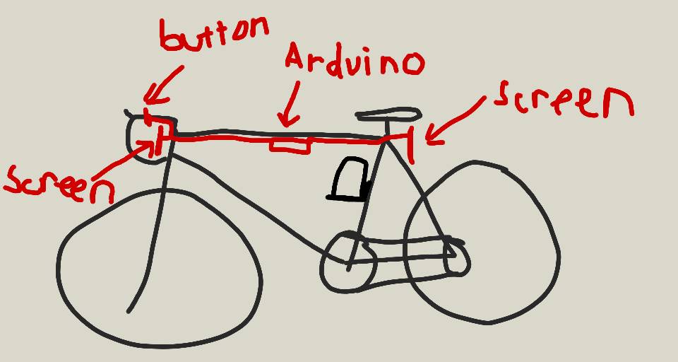
So this first sketch is the general idea, some kind of board in the middle with a battery, buttons on the handlebars, and screens in the front and back. I’ve started working a bit with Arduino boards over the summer, so that’s what I’m familiar with, but I’m hoping to be able to make my own board in the class, even if it’s just one following the Arduino spec. It’s also good to know that if my board is a complete failure, I’ve got a $20 backup plan to bring it all together.
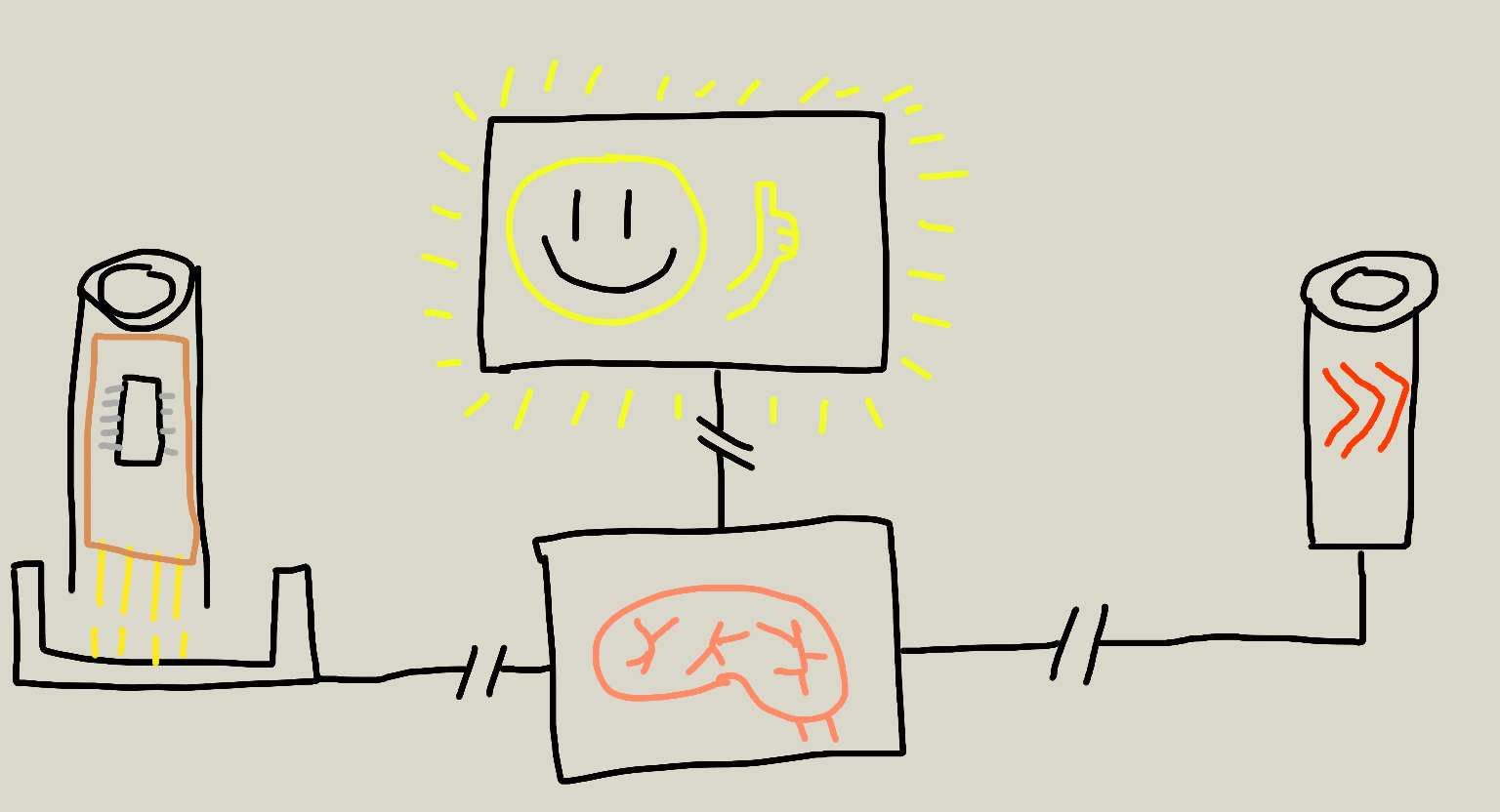
This is another rough sketch of what I have in mind, this time just of the electronic components. I have this idea that it would be cool for the emotes to be swap-able, especially if I can make them really cheap to make, so that I can load up 2 or three emotes, but swap them out or reprogram them easily. I’d want the blinker functionality to be hard wired though, since that’s so key to the practical function of this semi-fantastical rig.
I also tried my hand at modeling another sketch version of the bike and screens in Blender, which I’ve used before to manipulate some models created via 3D scanning. I’m embedding a sketchfab viewer, but you can also download the model as an obj file
I only really used a couple of different Blender skills in creating this model, which is why I stuck with Blender, even though it’s not easy to make it parametric (so this model isn’t). I created a few basic shapes, namely cylinders and two toruses for the wheels, and from there it was a lot of scaling an moving polygons along various axes. I learned the basics from this series of videos on YouTube. I have a three button mouse, which makes navigation easy once you get used to it. For manipulation my best friend is the combination of “G” and “X”, “Y”, or “Z”, which is the keyboard shortcut to move a selection along the x, y or z axes. The same combination works when starting with “R” for rotation, and it also works when you’re selecting faces in edit mode for an object (tab). The keyboard shortcuts became really intuitive, so that I was able to flow into creating the model more easily.
The hard part was the measuring. For instance, I made the handlebars by extruding a face from a cylinder, rotating it a bit, then extruding it again. When I finished, I found the handlebars to be too small, so all I could easily do was stretch that extruded cylinder sideways, which is why the handlebars look distorted. The only measurements I’m sure are accurate are the seat tube (61cm) and the wheel diameter (70cm), because those are the measurements that I know off the top of my head. The rest of the bike just looks about right, but if I wanted to adjust those measurements, it might be easier to start over.
Still, this sketch-like model helped me get a feel for how the two sizes of LED boards that I’ve found would fit onto the bike, which was helpful. I may go with what’s depicted here, which is a smaller board on the front, and a larger board on the back.
2018-12-14
I’ve been working on designing my control board for a while now, and I’m about ready to mill it. I started with the Adafruit tutorial for my LED matrix, and made sure that I could power and control the matrix from an Arduino board. That worked, but plugging in 16 jumper cables manually is not fun, so I haven’t been experimenting with the code until I can avoid that step with some stable pin connections. I looked at the data sheet for the ATMega328P, to try to see if I could reproduce the functionality that I had in Arduino without changing much by reusing similar pins. I had some pins guessed and had started my board design in KiCAD when I talked to Rob for a sanity check on my design. Rob suggested that I just find the Arduino pin mappings for my ATMega328P, and copy those, which sounded a lot easier, so I’ve been revising my board design based on this pin mapping and the jumper pin connection instructions from the Adafruit tutorial. The board has to be two-sided, and I haven’t done that before, but when I talked to Rob, he suggested milling the front as usual, taking out the board but not the copper frame, then flipping the milled board back over to mill the other side. Instead of trying to line the board back up where it was, I’ll put it against the edge of the copper frame, and then offset the origin by the known value of the drill bit width. With any luck, I’ll have a milled board by the end of the night.
2018-12-16
Milling the board on Friday didn’t work out for a few different reasons. First of all, the 1/64 endmill that I used was in bad shape, so all of my traces came out really rough, and I even lost a pad. Second, the holes for the vias in my board were much too large, so they overlapped somewhat. Third, those vias were also mirrored, because I must have left the box checked when exporting to SVG from KiCAD. The upside is that that mirroring on export exists, which is what I’ve been using for the reverse of my boards.

Yesterday, I went back to the lab to try milling again, to see if I could get a better result. I found this rivet tutorial from a previous iteration of the course. That was really helpful in determining what my rivets needed to look like, and that I would need a separate layer for the drill holes. In total, I need four layers, front copper, drill holes, edge cuts, and back copper. That’s also the order in which I mill them.
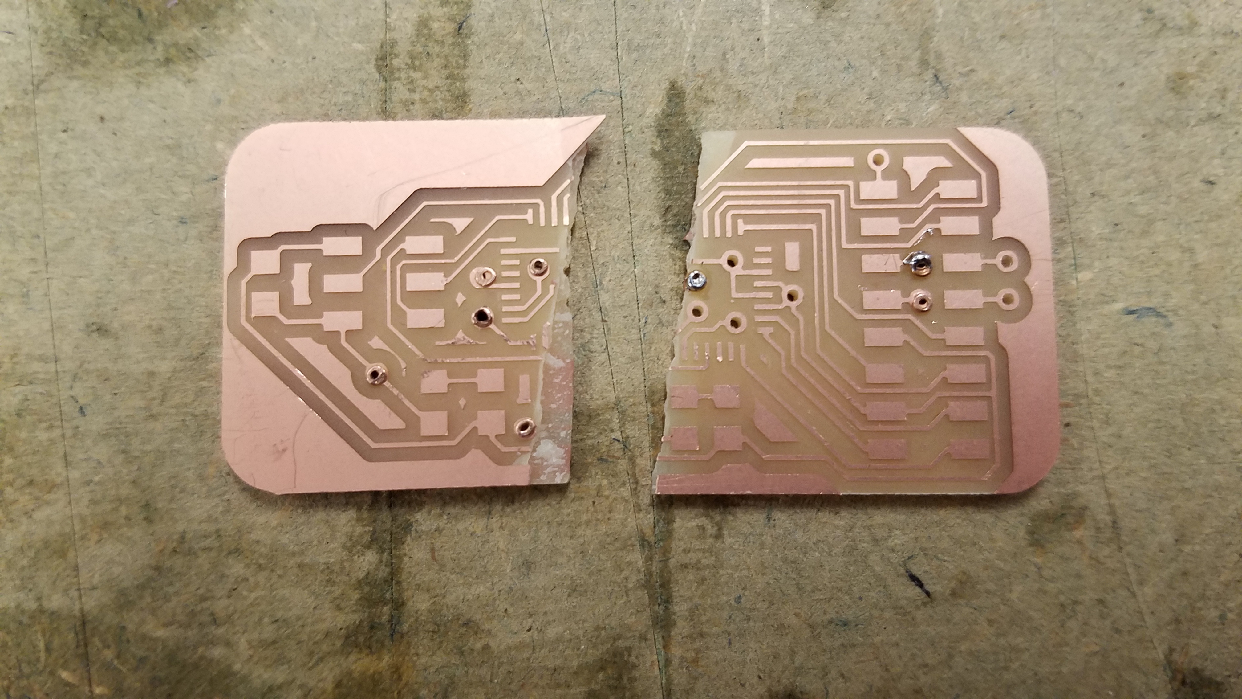
The positive outcome from my time in the lab on Saturday was that I got used to milling two sided boards. The negative outcome was that neither of the two boards that I milled were viable candidates for stuffing. The first one that I milled I broke in half while hammering in rivets. I was propping the board up slightly, so that the boards would have room to poke through on the other side, but that also created a point at which the board was likely to break, which it did.
The second board that I milled, I was able to rivet successfully, and tested all of my connections with a multimeter. This was important, because problems with the vias would be difficult to troubleshoot on a stuffed board. Several of my pads weren’t connecting to each other, and it seemed to be the case that the solder that I used on the vias formed an air bubble inside around the rivet, instead of connecting to it, so what looked from the outside like a good connection was not, when tested with the multimeter. I also found that the clamps in the shop were good for gripping the board vertically, so I could verify that both sides of the vias were connected.
With the traces on both sides connected and verified with a multimeter, I could try to solder on my microprocessor. This is where more trouble started. I had thought that the microprocessor had enough clearance for rivets to fit underneath it, but this was not the case, even with the rivets hammered all the way down. The ATMega328P is a difficult chip to solder under the best of circumstances, but with the chip pads a half millimeter away from the board pads, I wasn’t able to solder connections without connecting multiple processor traces.

Today, I’m trying to mill a board from a new design that I made last night, which is larger and less space efficient, but which doesn’t rely on having any rivets beneath the processor. I’m writing this as the front copper traces are milled, so I’m hopeful that I’ll be able to stuff a board today, and maybe even get some demo code loaded on to it. I’ve also been tracking my changes to the board in a GitHub repository, which has been a good way to make my board files available across my laptop, desktop, and the milling PC.
First attempt at milling the larger board failed. At the last step, I didn’t properly reverse the board to mill the back copper layer, so none of the vias are in the right place, and all of the traces are rotated 180° from where they should be. Now I’ll try again, and try to pay better attention while flipping the board.