Work Progress
For this week, we are supposed to make network communication between projects and devices. First, I choose to make RN4871
(2.4 GHz Bluetooth) I started with Neil’s example board and add 2 LEDs (Red and Green) for debugging.
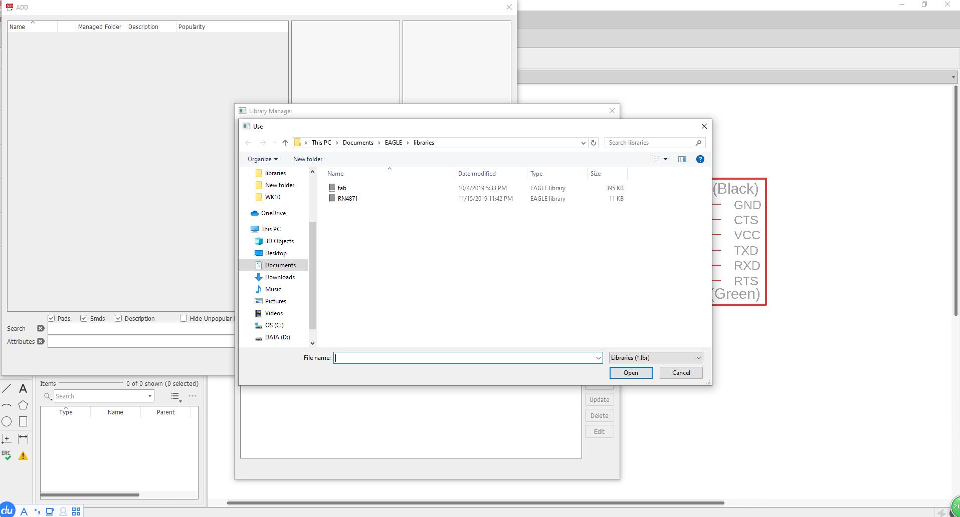
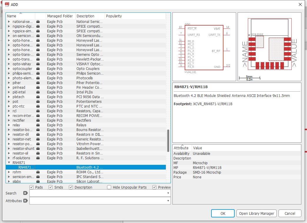
I added RN4871 to my schematic from the eagle libraries pointed by Rob Hart’s tutorial.
He also linked us to another programming tutorial, Arduino with RN4870,
which I think is super helpful.
My schematic:
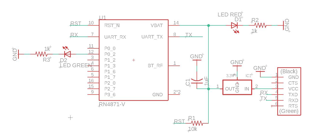
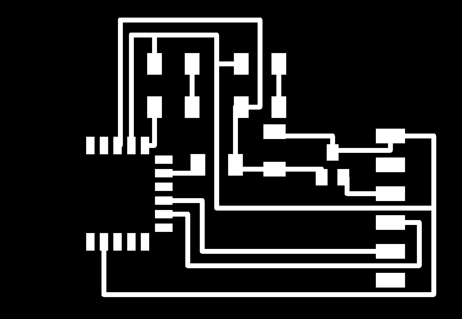
My board traces:
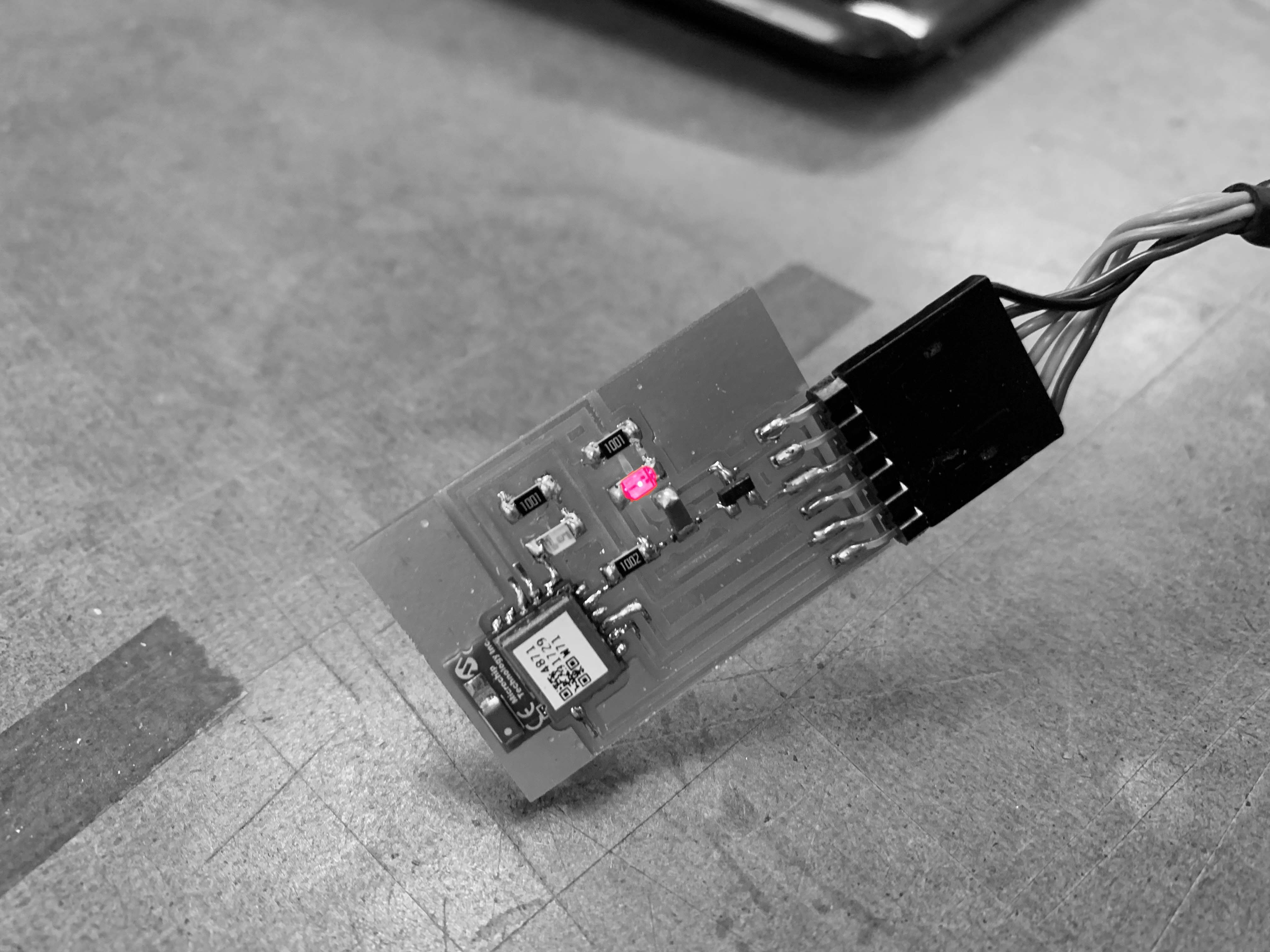
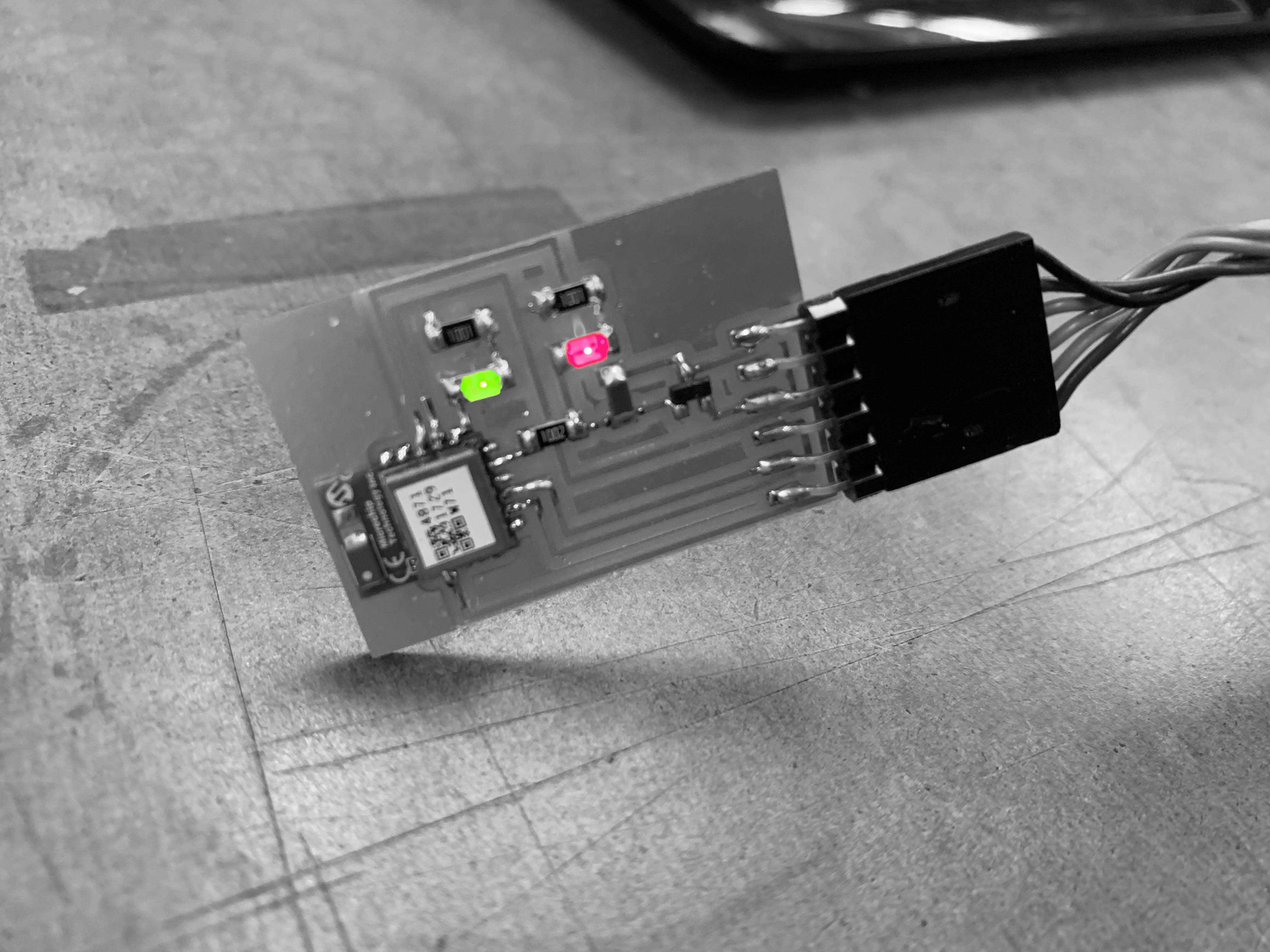
Soldering:
RN4871 is extremely hard to solder! Its pins are super tiny. I am always very cautious of soldering the components because I do want
to avoid and not deal with hardware issues when programming, but this time, I am not confident about the soldering quality at all. My
previous experiences told me it become very troublesome when you want to debug a hardware issue(shorts or other problems), so it’s better
to be cautious and always check your board each time you solder a components on.
After the board is done, I connect it with the computer in the architecture shop, the lights immediately turns on, a good sign to start programming.
Here is my programming process.
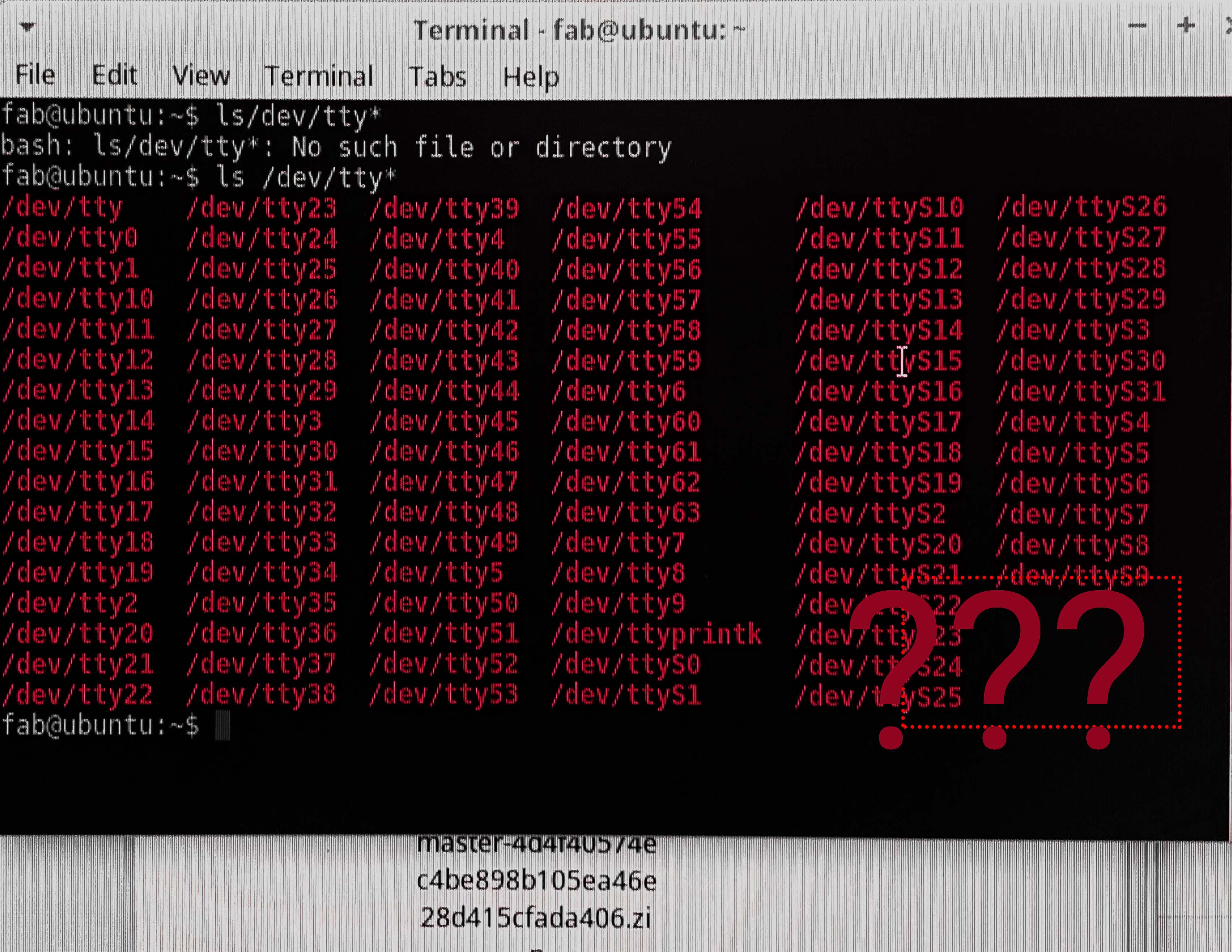
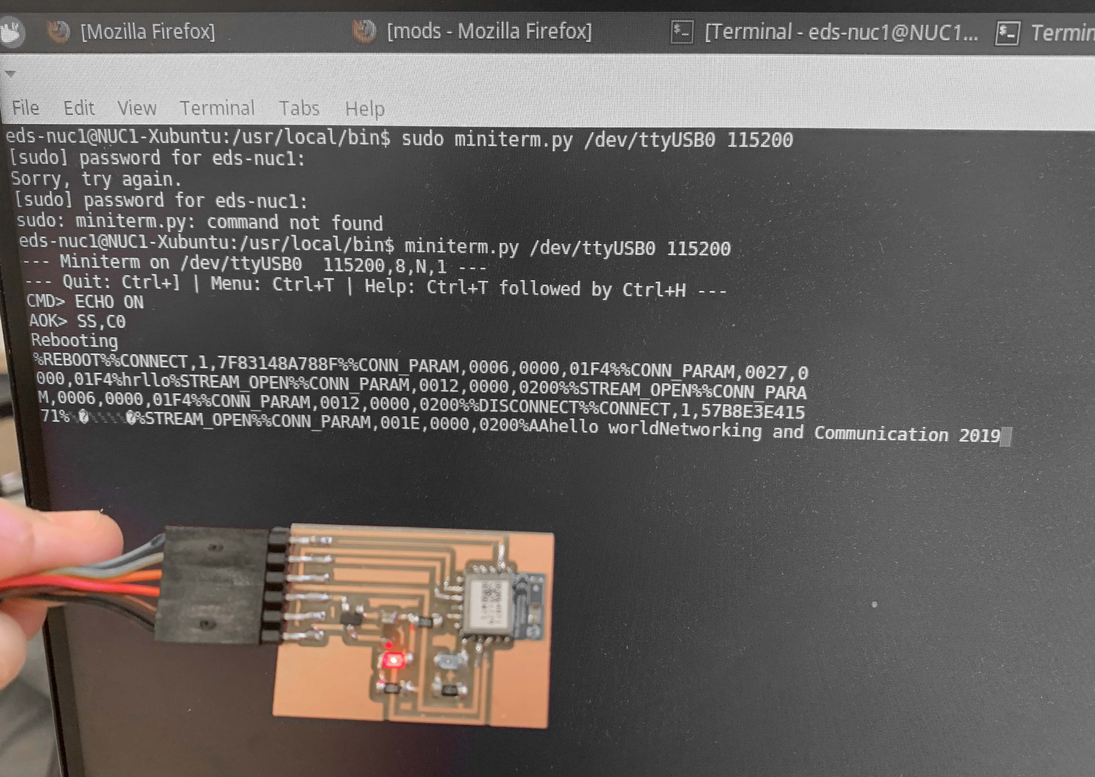
I had a hard time finding device ports from the architecture computer, and finally found it on the computer of EDS (EDS computer always works). Once I found my board and know the port name (Check Week 9 for tutorial of finding port name), I run the following commands:
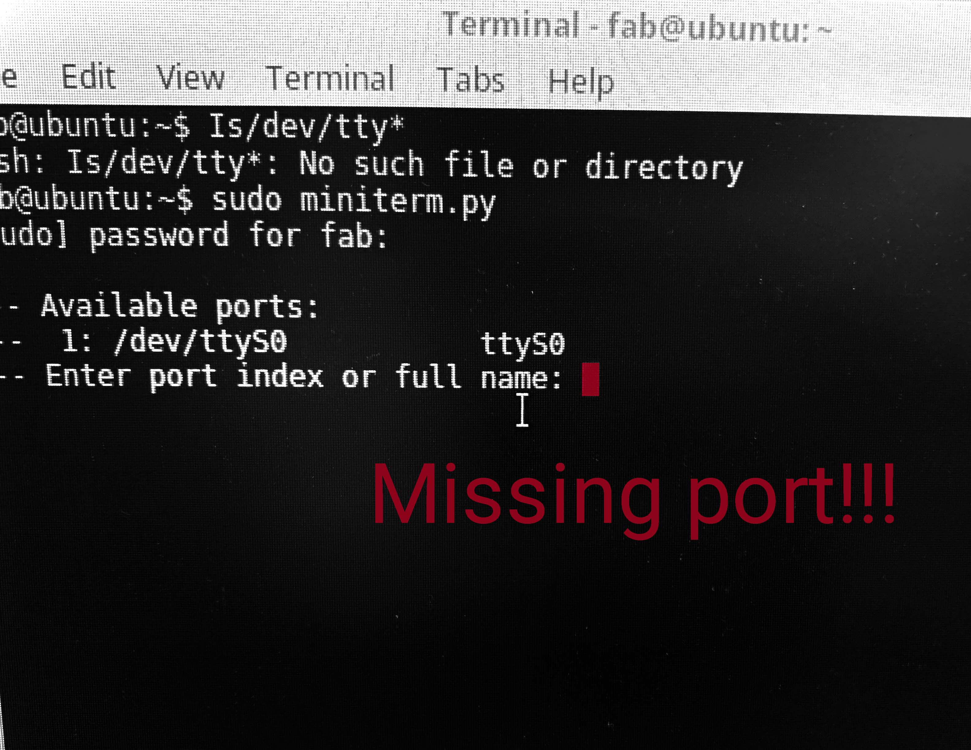
Struggle for finding the port:
Now my board is ready to communicate computer and my phone. The programming part went surprisingly smooth! Then, on my phone, I downloaded an app, LightBlue. My Bluetooth is immediately detected by the app under the name of BLE-FB03. You should have a similar name like BLE-XXXX with your chips.
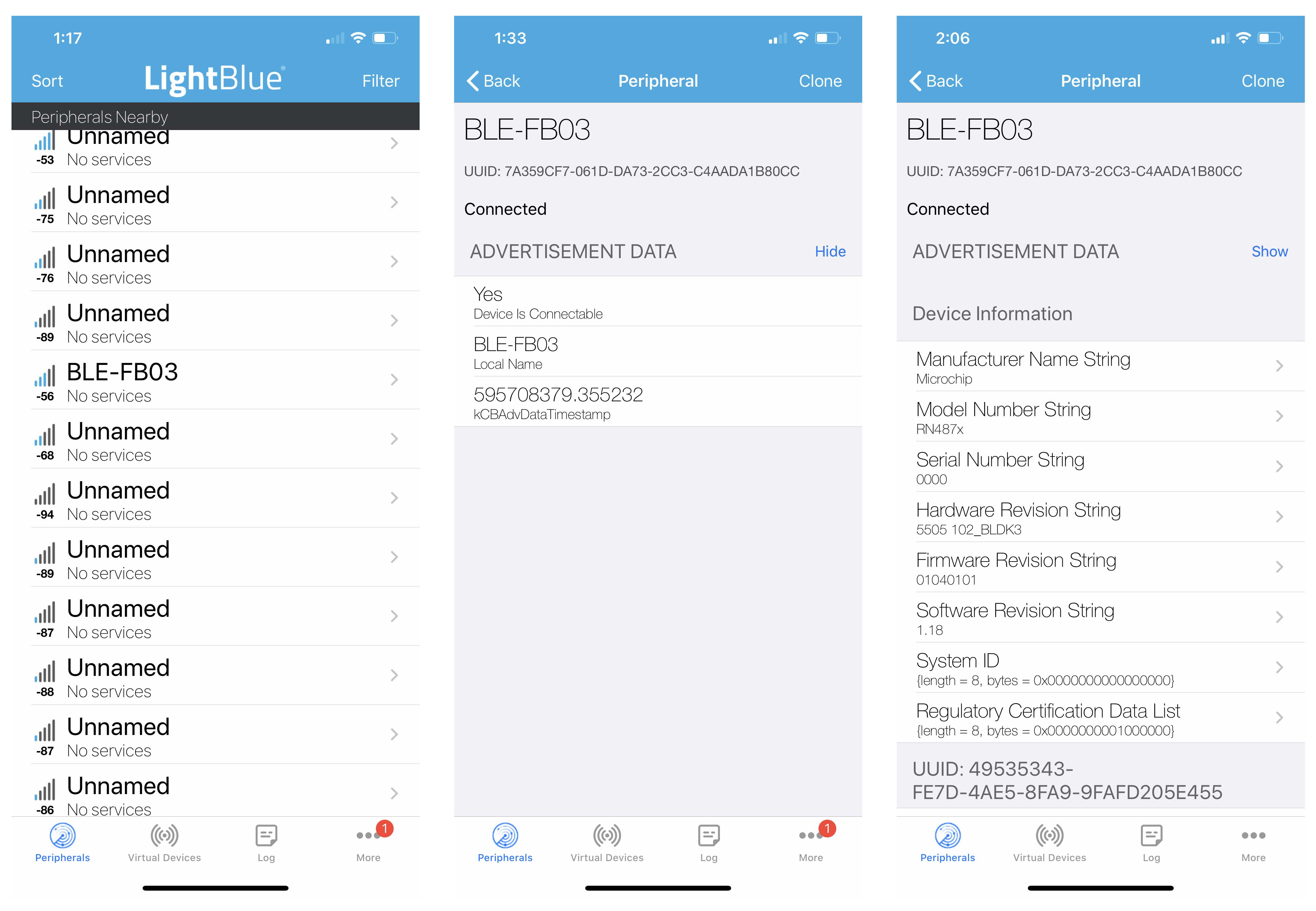
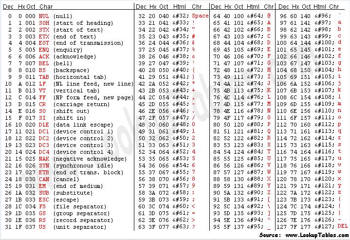
After it got connected, I can send messages between both devices. You may also change the way of message representation from HEX to ABC/ASCII.
ESP32-Wifi(Communicate Input and Output devices)
This week, I still had extra time continuing exploring other communication chips. Therefore, I decided to make an ESP-32 Wifi. The board example provided by Neil is doing the same thing as this product.
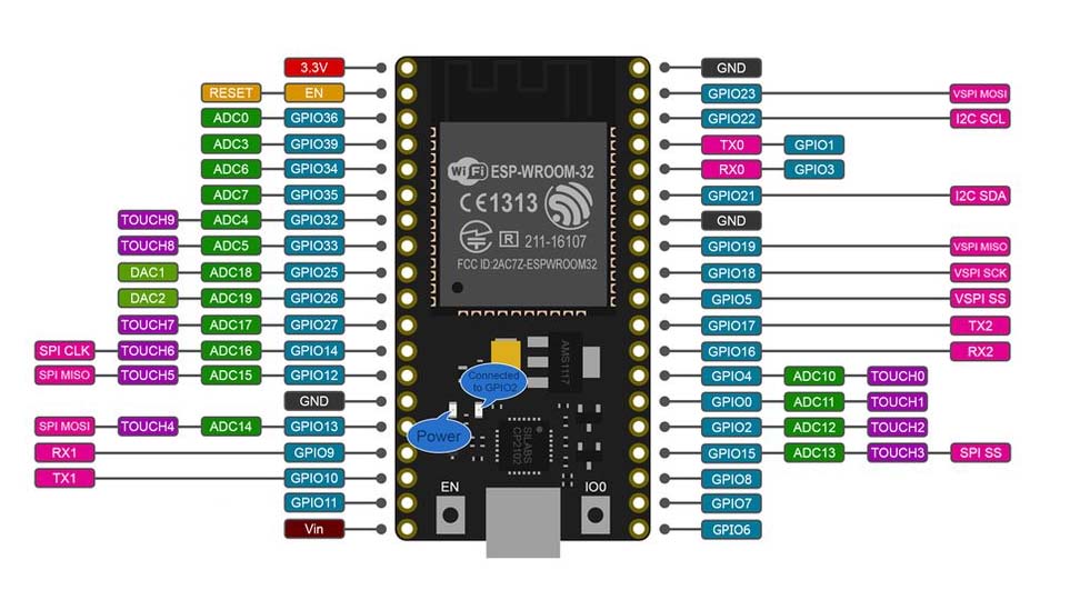
I hope to make my input device and output device communicate through ESP-32 Wifi in the final project, so that the stepper motor can respond to the distance values detected by the ultrasonic sensor. This process is somewhat abstract, so I made a diagram to help me understand how to do this. The basic principle of this diagram is to use client and server as the central hubs to transfer and receive information.
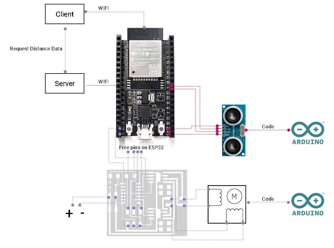
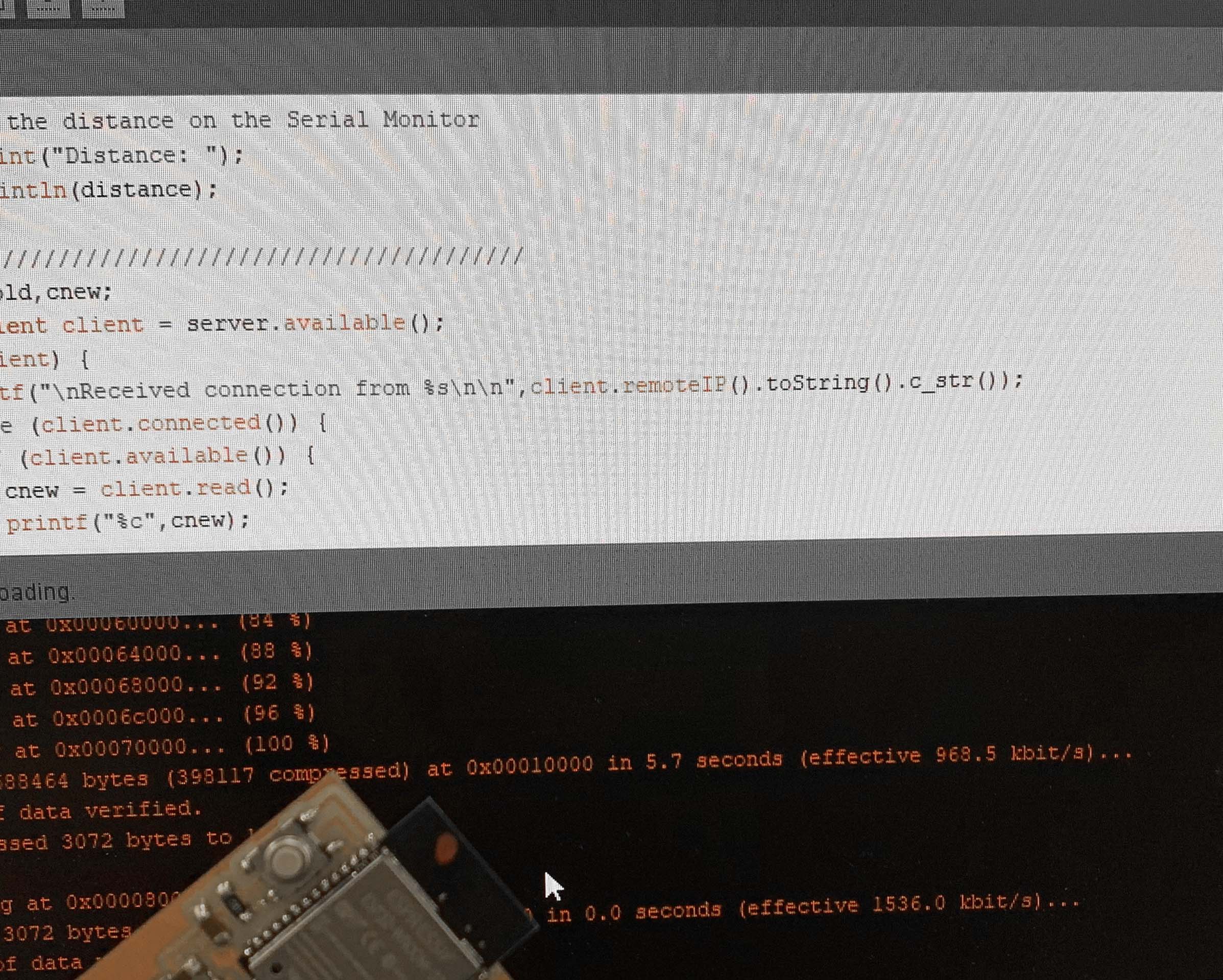
Arduino code I will use for communication between both devices.(Great Thanks to Anthony who helped me on the code)
However, I realized that I had a misunderstanding about ESP-32. I always thought of it as a hub station, but it really had the same role and function as Attiny and Atmega. It is a microcontroller! (Please correct me if I still misunderstand something here.) The reason for my misunderstanding is from this video. Matthew Hallberg used Arduino as a microcontroller to connect an ESP-8266 and a motor driver to drive his car and let the car communicate with the unity interface. To my surprise, so does this mean that there were two microcontrollers in the project? I am confused about the actual role of ESP would be in a project.
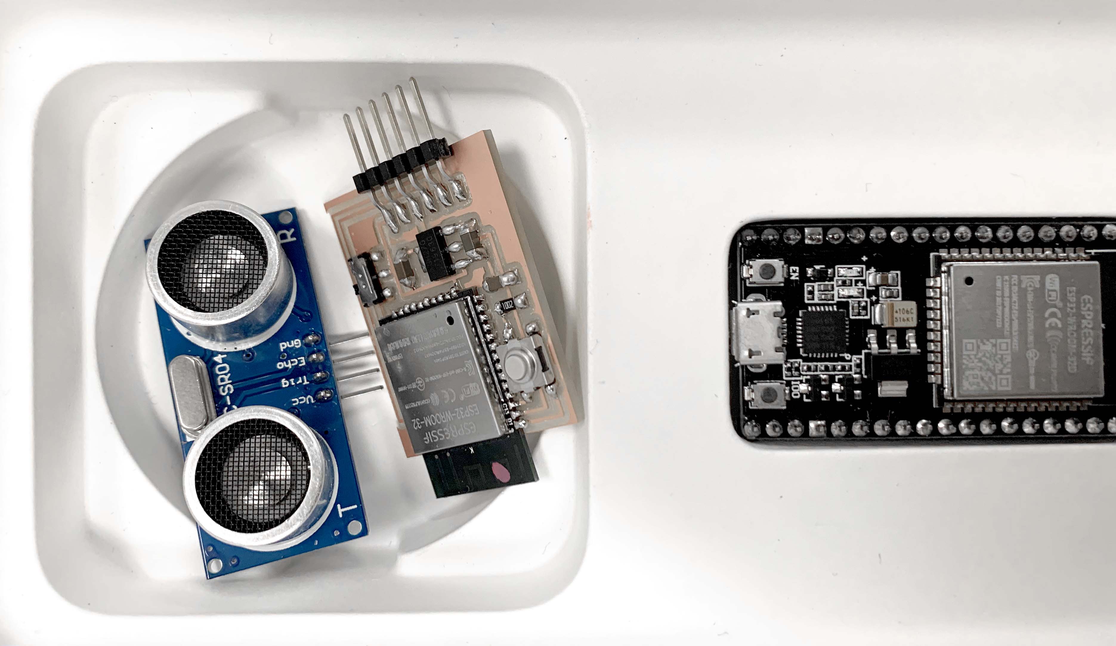
Anyway, I'm going to start with Neil's board example. This board is the most successful one I've done for this semester. It's easy to mill, solder and program in one time without any debugging. I wish all my boards were so obedient.
Note: In order to program ESP in arduino IDE, you need add and install ESP board by first finding preference and copy "http://dl.espressif.com/dl/package_esp32_index.json" in the additional board manager urls, then you are good to install ESP in your board manager.
When I wanted to get input and output talk on ESP32, I ran into this unexpected programming problem. According to the Internet, this is the most common problem experienced by ESP32. The solution is to hold the button down until you click on the upload in the Arduino IDE, and then keep your hand on the button until the upload succeeds. Unfortunately, the problem has not been solved.
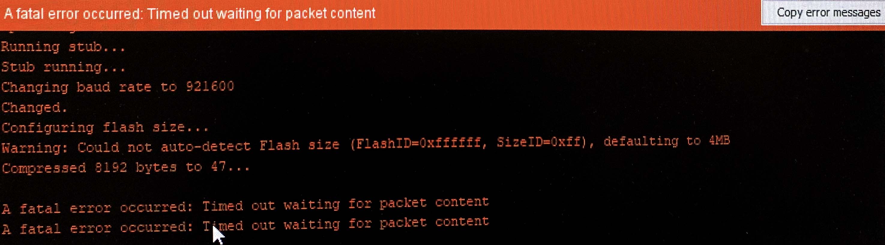
I went to many TAs for help, but this problem could not be solved, it showed connecting and fatally failed forever. At this point, I had spent a lot of time on this. Even when I tried to use the built product to program my sensor and motor, this problem still existed. Finally, Alex advised me to switch to Atmega for input and output communication if WIFI was not necessary for my final project, so I was forced to give up the option of ESP32.