Work Progress
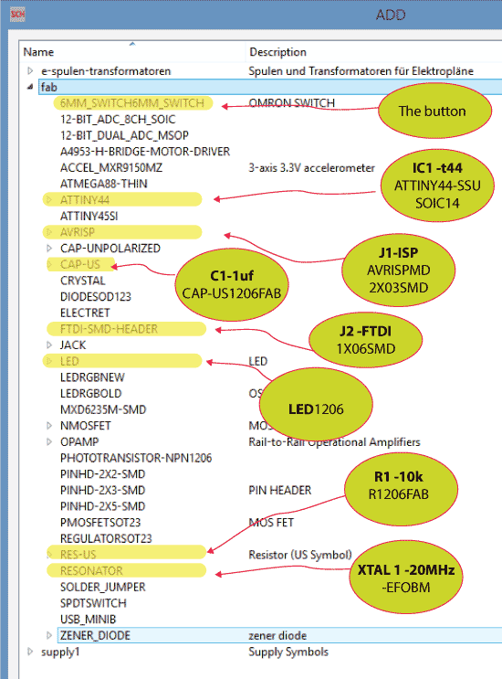
This week we are required to use Kicad or Eagle redesigned Neil‘s hello world board, and add (at least) a button and LED (with current - limiting resistor).
Since I was not very familiar with circuit design and fabrication, I decided to follow the page instruction of previous
students and then use the workflow as the basis to understand the circuit board's circuit logic.
I found Molly's page is very detailed
instructed. At the same time, I also found Eagle's basic tutorial on youtube, which provided intuitive instructions on how to create and draw a project in Eagle.
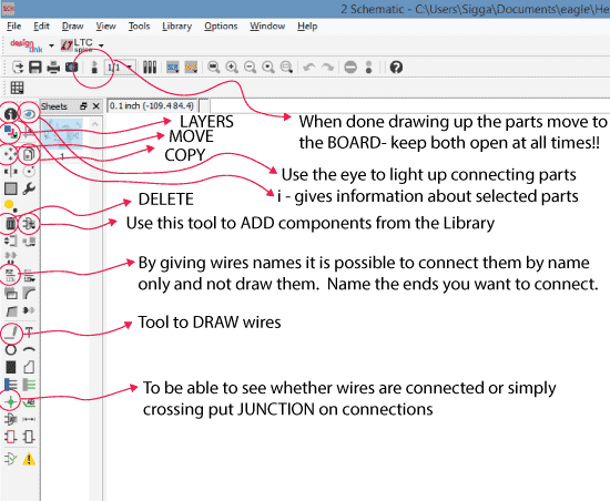
Initially, I didn't know I could connect components using the Name function, so my schematic was very messy, so I changed it. Here is the final schematic.
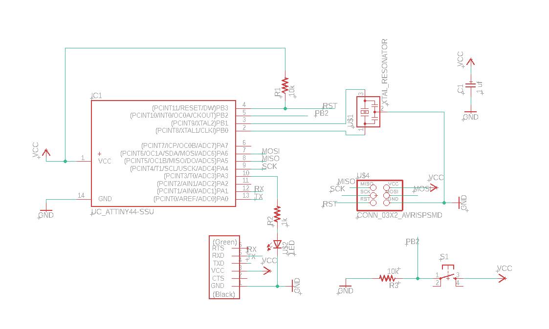
I then created the corresponding board by clicking on the BRD icon in the top bar. The difference between board and schematic is that it's just a diagram, not thinking about physical space or units, just making sure the correct components are connected, whereas board is the form of the circuit board that we actually get. The width of the connector in the board interface and the layout and size of the component are the same.
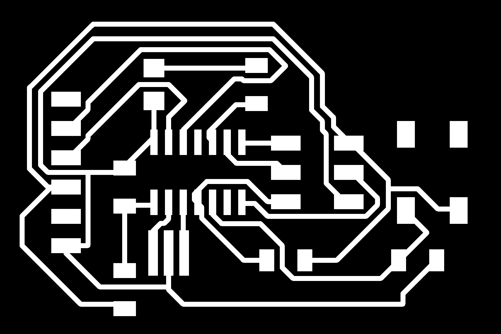
At the first attempt, I ignored the importance of the design rule, resulting in my route being too thin. After Anthony's reminding, I changed the design rule from 6mm to 16mm and rerouted the new board. (I actually know that the design rule needs to be set, but I ignored it because I repeatedly modified, redrew, delete board files between schematic and board.) I don't know why my airwire is very messy, which caused me to spend a long time drawing the board well. I even added a VCC component Resistor (0) to jump lines. And then there's the export, which I've set to 1000dpi monochrome.
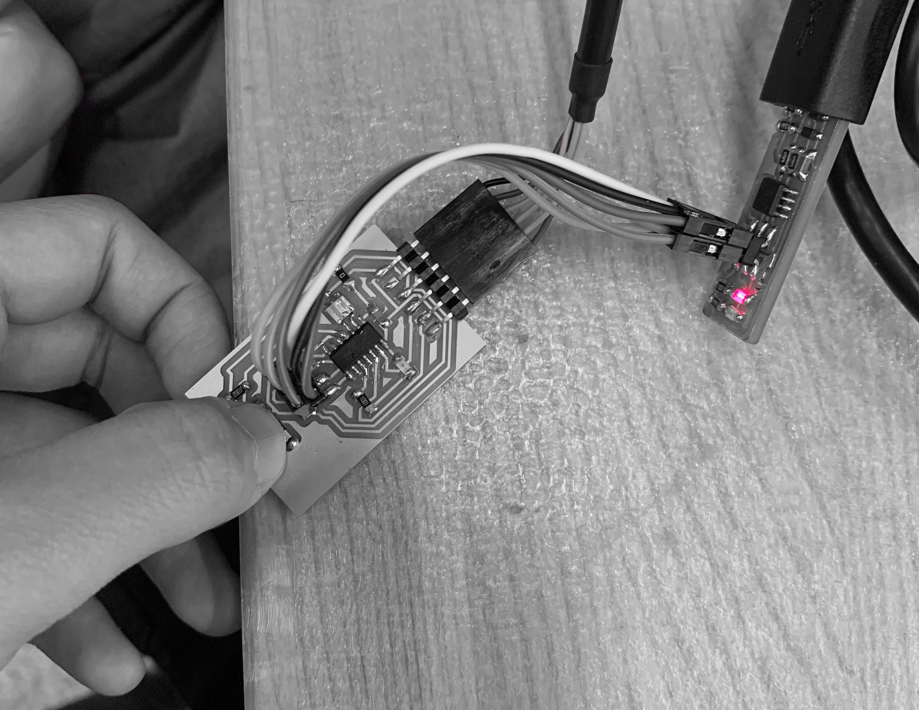
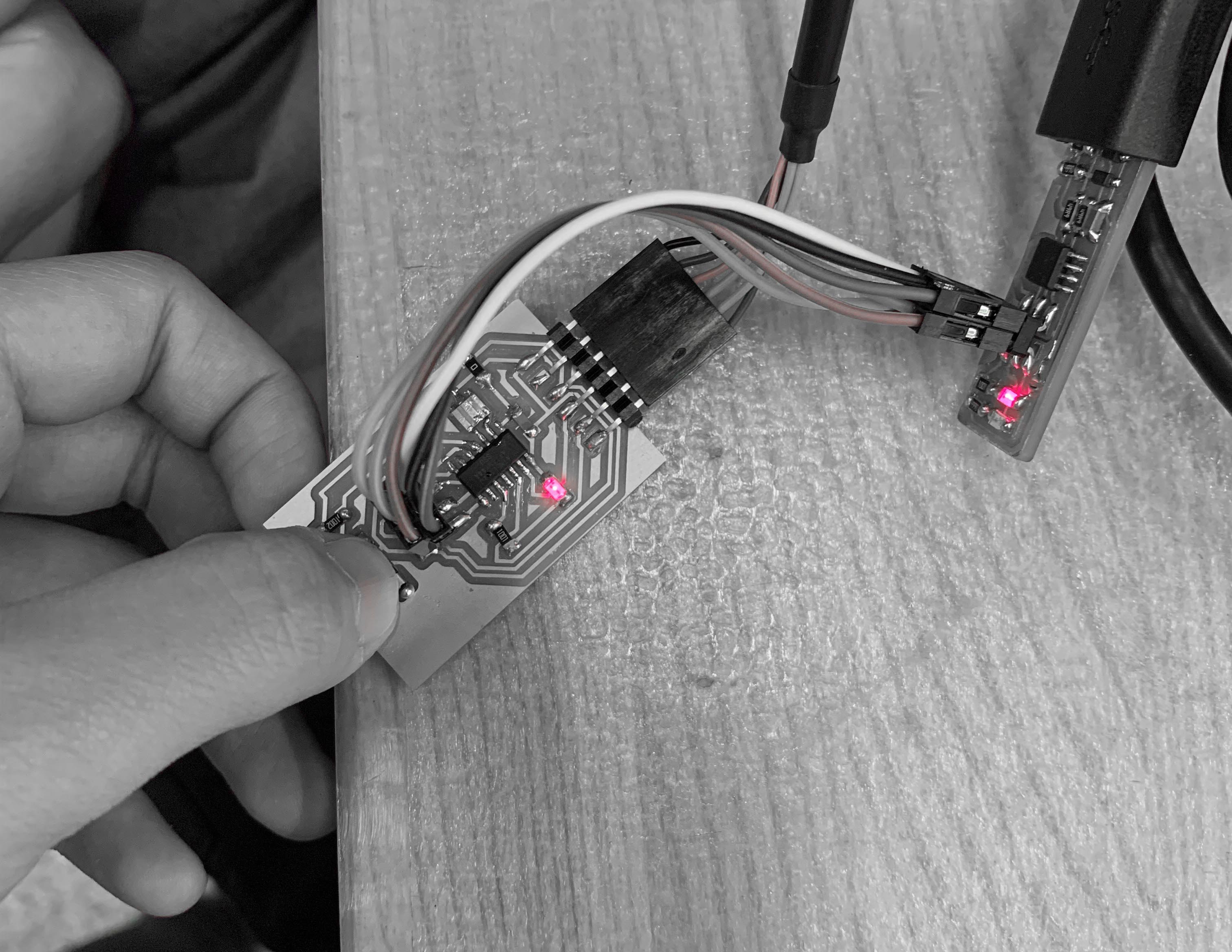
Soldering is going very well this week.
A few caveats:
On a multimeter the black lead is the negative and the red positive. Press the center button till you get this arrow symbol in the right-hand corner of the screen. When the LED lights up you know that The end where the black lead is touching is the minus-therefore that end should be connected to the ground.
Led Resistor calculation:
The When calculating what the size of resistor we need we use Ohm 's law: I = V/R.
I stand for current in units of amperes (A).
V is the potential difference measured across the conductor in units of volts
R is the resistance of the conductor in units of ohms.
To be able To calculate the resitor for the LED we need To find the data sheet for that led. we find a link To the LED in the FabAcademy weekly schedule, week 6.
Our calculation looks like this:
We start by changing the mA into amps = 0.01A.
We know that We will be taking in 5V so We find the difference
3.2 V / 0.01 A = 320 Ω
We need 32 Ohms o or who for the resistor, so we take 499.
The blink code was uploaded, and the Program was very smooth!