week 04
ELECTRONICS DESIGN
Tools + Methods
Eagle
Roland Modela
Soldering
Like Week 02, this week left me mystified about what exactly it was I was making. I again decided to follow the instructions of someone else and just focus on getting the work flow down. This week we fabricated the hello-world board adding a button and LED. I found it useful to follow the pages of Fab Lab alumni Gabriela and Sigridur
Board Design
Drawing the Board
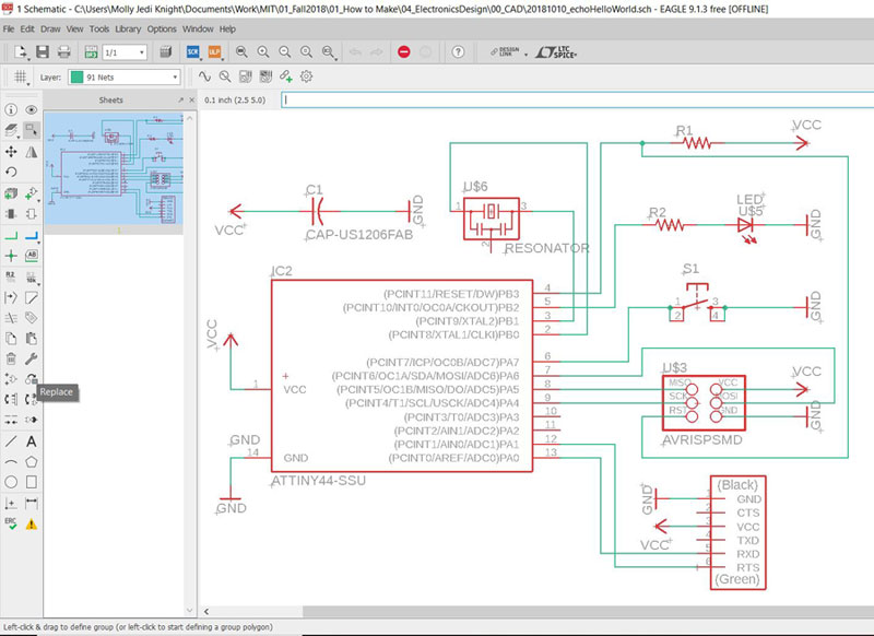
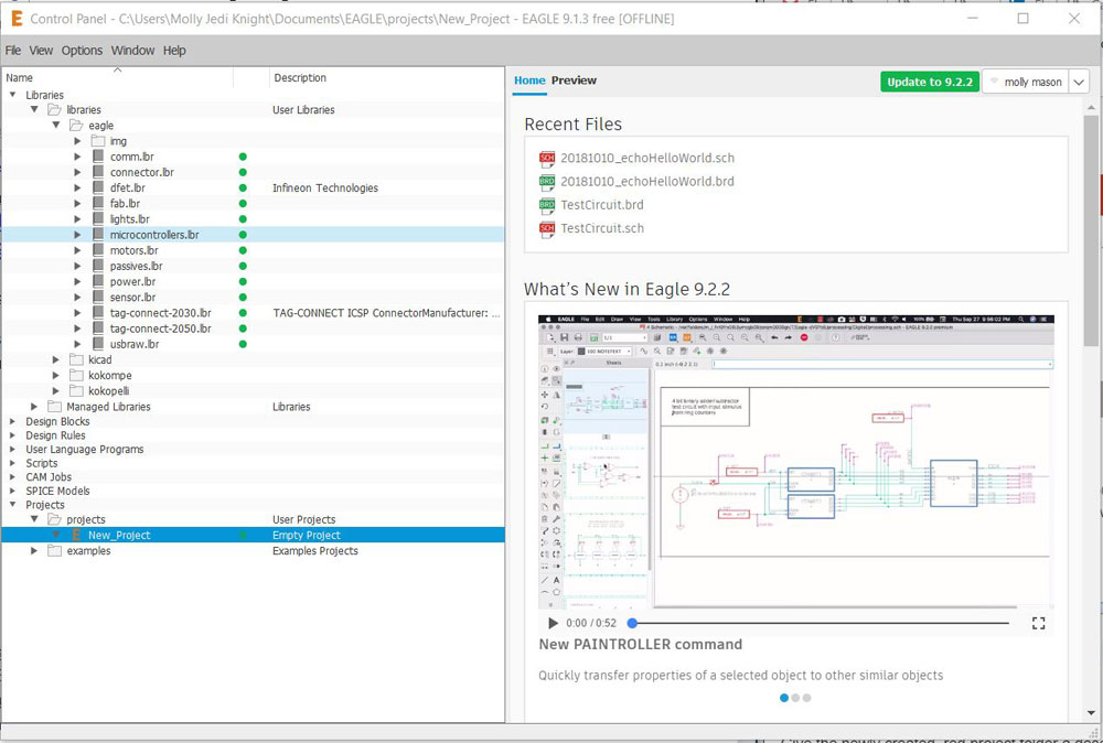
I used Eagle to redraw the hello-world board. The first step is to make sure you have the fab lab library installed on Eagle. Place fab.lbr into the Eagle Folder on your computer. It should look something like: C:\Users\[user name]\Documents\EAGLE\libraries. Now when you open Eagle you should be able to expand the libraries folder and see several libraries there. Make sure the little dot next to them is GREEN. If it’s grey then you can click on it to activate.
Eagle operates similarly to AutoCAD which operates between Paper and Model Spaces except in Eagle you switch between SCHEMATIC and COPPER spaces. The SCHEMATIC is purely diagrammatic (and doesn’t consider physical space or units) and it helpful to make sure the right components are getting connected. COPPER is where you design what you will actually mill.
Since I'm new to Eagle these were the basic commands I needed to learn:
ADD : Places a component on your diagram (You can use *[search term]* to search the library)
NET : Draws a connection between components
ROUTE : *ONLY USE IN COPPER REP* Creates a connection between components. This is what is actually milled.
NAME : You can name your NETS. If you name them the same thing then they will connect to each other.
RATSNEST: In copper space. Will help unscramble your net connections.
LINE/POLYGON: In copper space. How to make outlines for your board
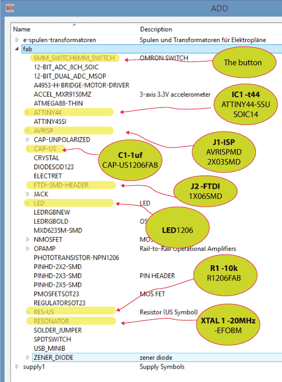
I added the necessary components for this week using ADD. I found the above screenshot helpful to navigate the Fab Library as I didn't know what anything was I then drew NET's between compoentns within the schematic space.
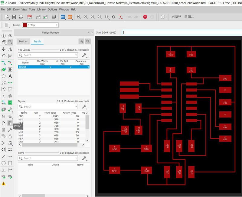
Then I switched over to the COPPER space where I could now see light grey lines connecting my components. Between using RATSNEST and moving the parts, I was able to get them in an untangleable order. Then I was able to draw Routes between components. Some important things: Keep in mind what layer you're drawing on. Use Design Rules (Edit>Design Rules. Use a min route width of at LEAST .05 mm and separation distance of .02 mm). You can check Design Rule Errors using DRC.
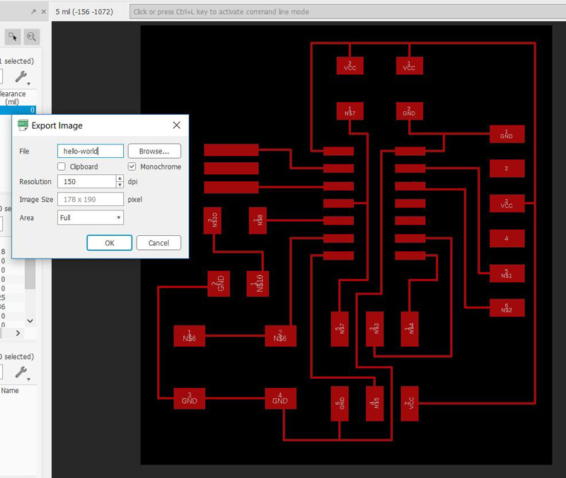
To get a trace file for fabrication go to File>Export>Imge and make sure monochrome is selected. You may have to toggle with what layers are being printed.I changed all my traces and components to "TOP".
Fabricating the Board
Once I had the traces from Eagle, I used CBA Mods to fabricate the board on the Roland Modela. Fabrication went similarly to Week 02 EXCEPT that I was using my Mac this week. Because new Macs have a retina screen, I learned my PNGs were exporting at 200%. An easy fix for this is to increase your resolution in Mods.

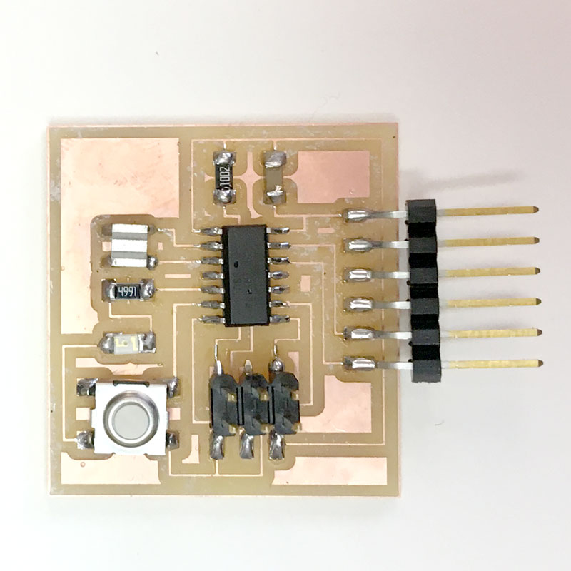
Stuffing the Board
Now it was time to solder my components. This week I needed:
1uF Capacitor
LED 1206
ATTiny 44 Micro Controller
1K Resistor
499 Resistor
Button Switch
Resonator
FTDI Pin (This comes in long line. Just snap off 6)
I found out later that FTDI pins are not self supporting. You should NOT let them cantilever off the board like I did.
***UPDATE*** 10/20/18 : I learned this board is milled incorrectly! To see revisions, visit week 06
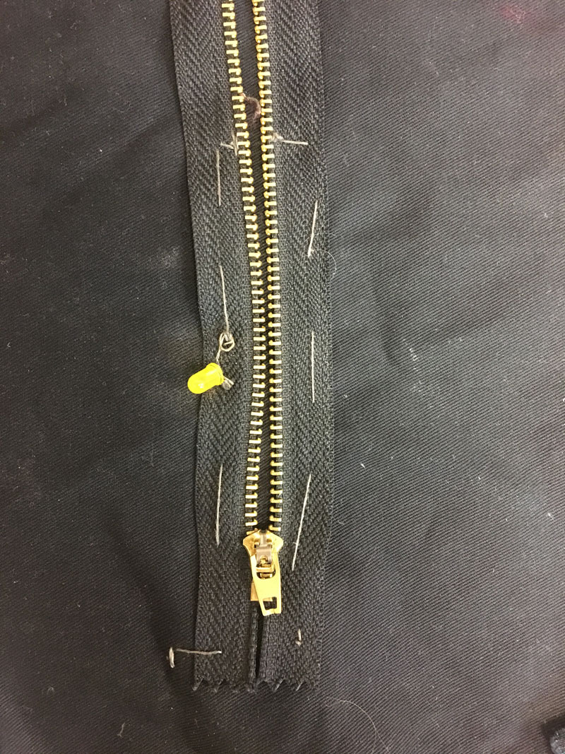
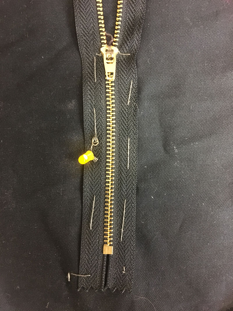
Bonus! Conductive Thread
I'm still interested in trying to incorporate some kind of sewing art into these circuits. I decided to make an analog circuit that used a zipper as a switch. I used conductive thread to connect an LED, battery, and zipper. When the zipper is zipped it closes the circuit and turns on the light. I'm not sure if using this method of switch will electrocute me when connecting to microprocessors and using higher voltages. Probably? TBD!
Files
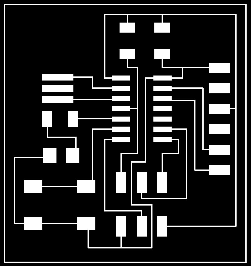
Board Traces
Board Profile